Civil Engineering Assignment: Fluid Mechanics and Hydraulic Design

Verified

Added on  2022/08/13

|8
|1453
|21
Practical Assignment
AI Summary
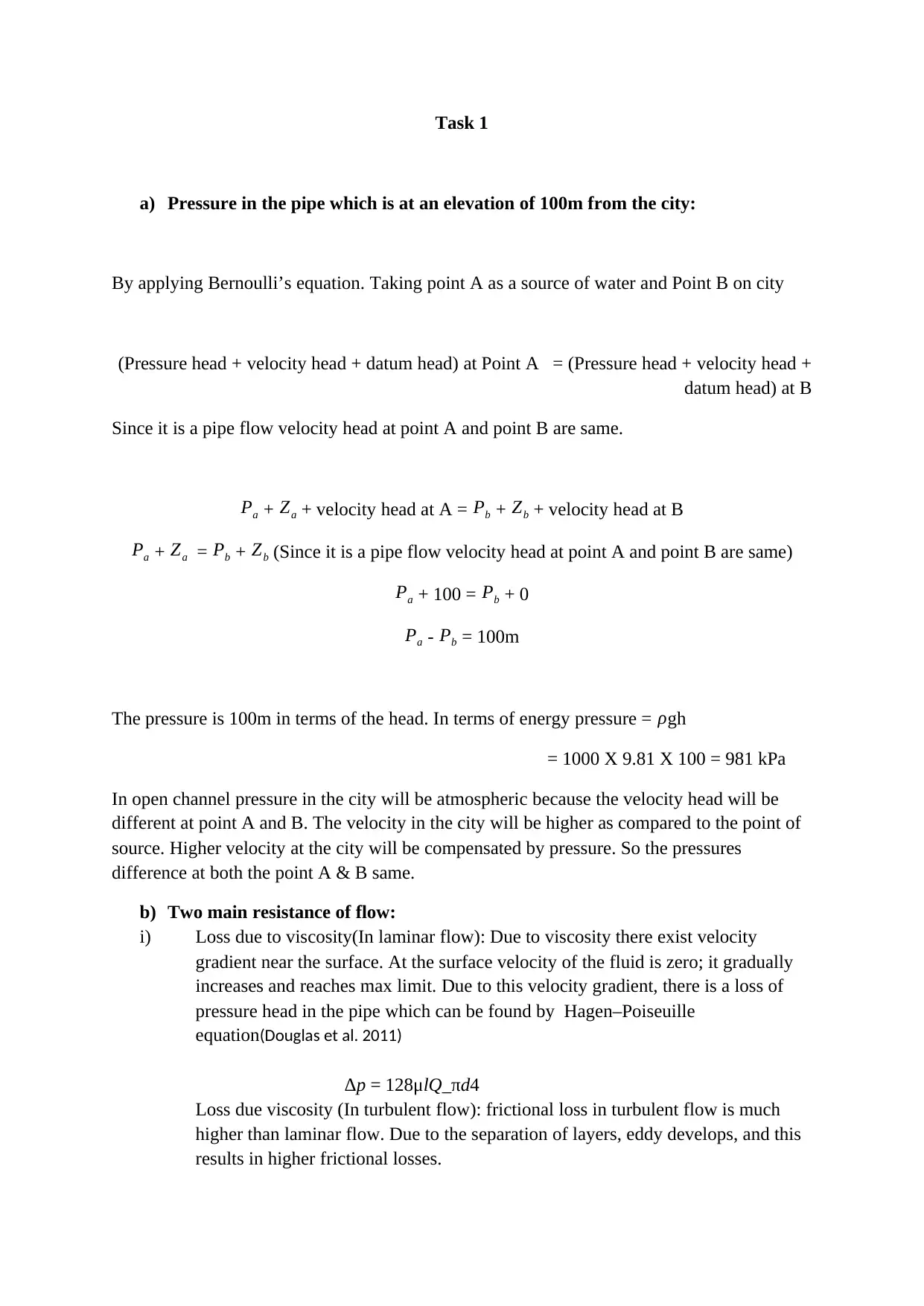
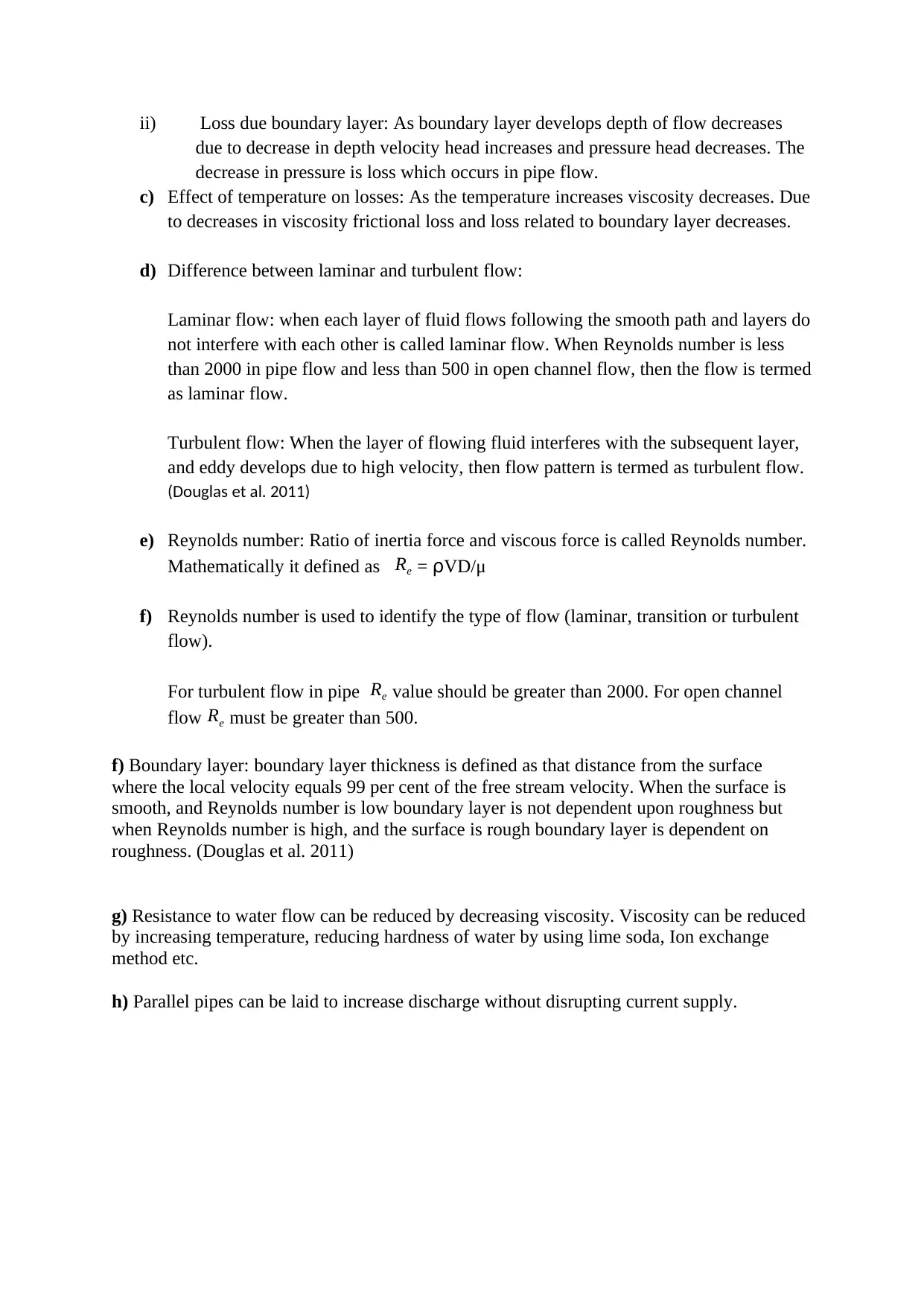
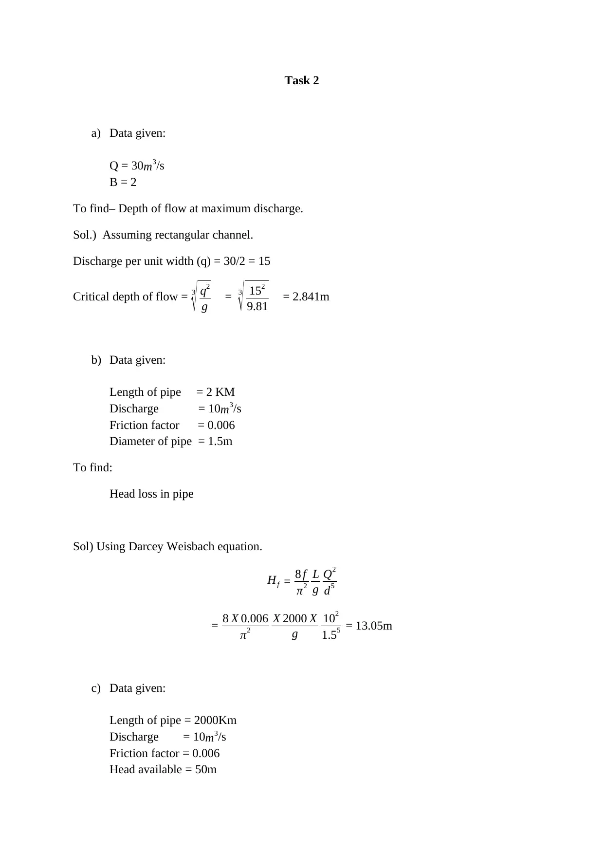
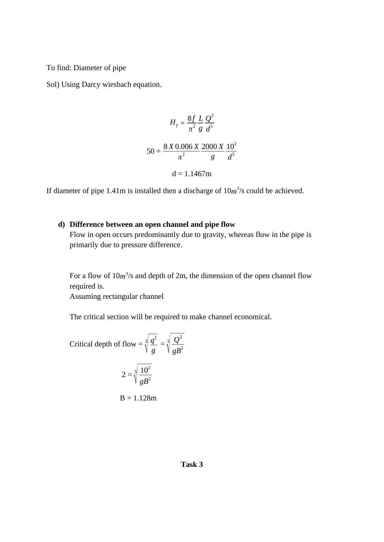
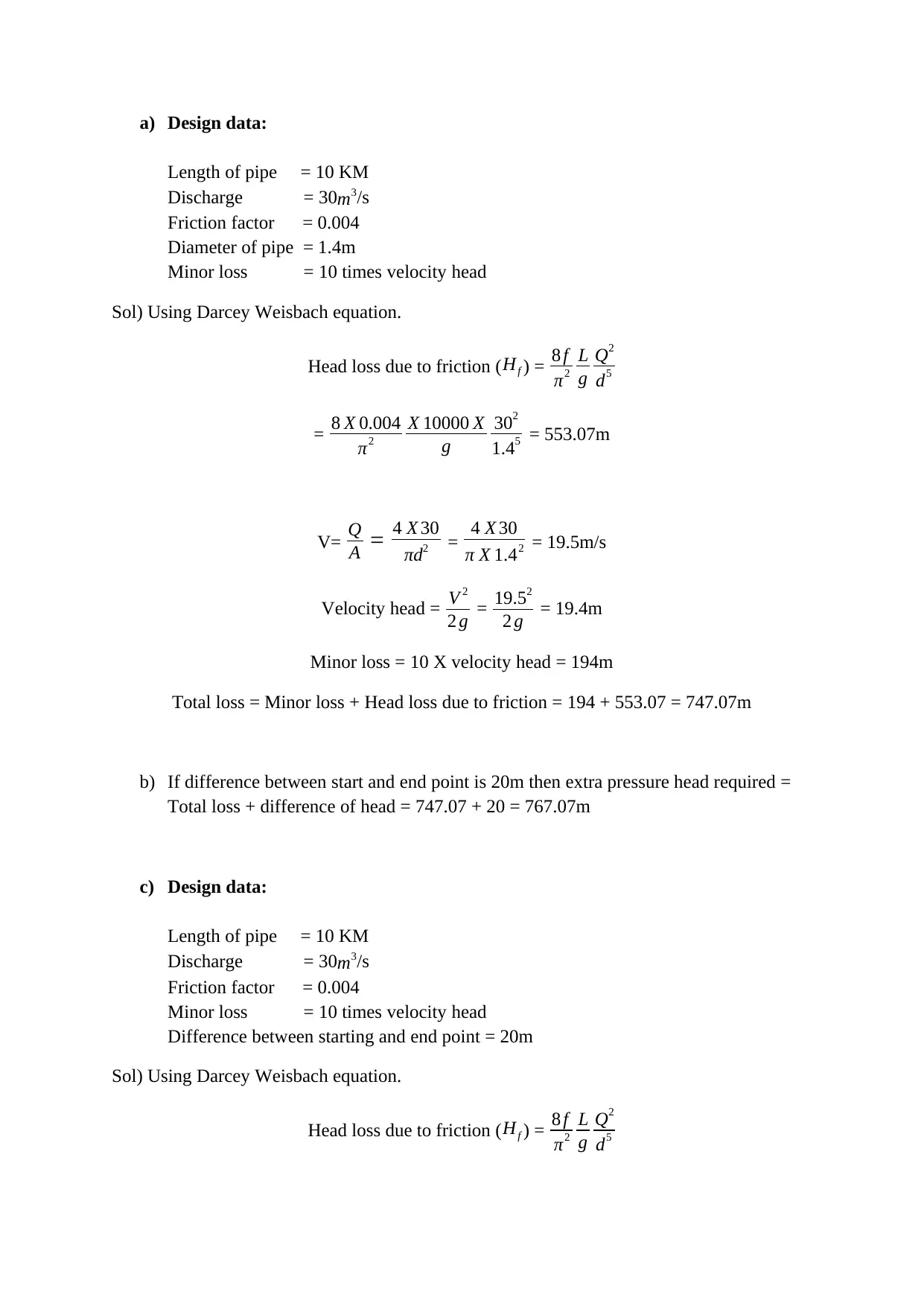
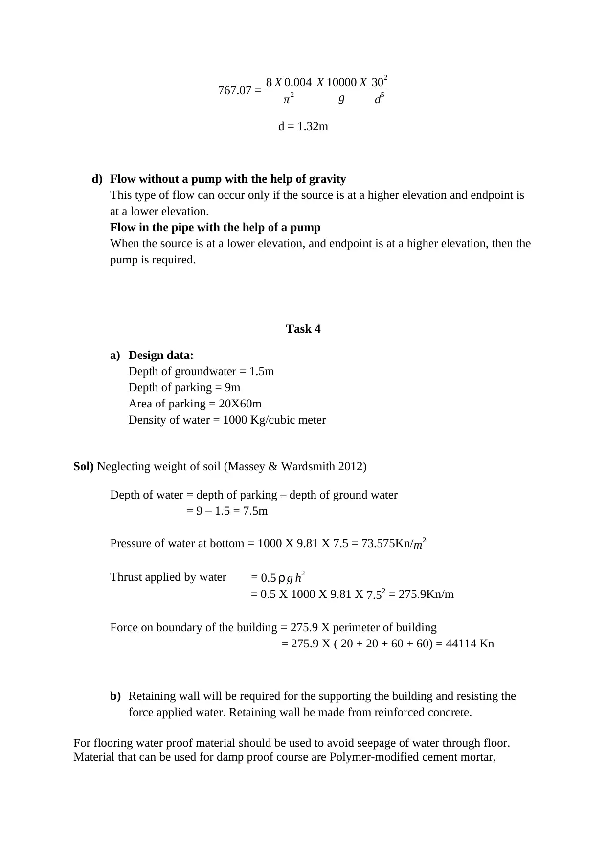
This assignment solution addresses several key concepts in fluid mechanics and their practical applications in civil engineering. Task 1 analyzes pressure in a pipe using Bernoulli's equation, differentiating between pipe and open channel flow, and exploring flow resistance due to viscosity and boundary layers, including the effects of temperature and the difference between laminar and turbulent flow, and the significance of the Reynolds number. Task 2 focuses on calculating the depth of flow in an open channel at maximum discharge, head loss in a pipe using the Darcy-Weisbach equation, and determining the required pipe diameter for a given discharge and head loss, and the difference between open channel and pipe flow. Task 3 involves designing a pipe system, calculating head loss and minor losses, and determining the extra pressure head needed, also exploring flow with and without pumps. Finally, Task 4 addresses groundwater pressure and the design of a retaining wall to support a building, emphasizing the use of waterproof materials. The solution includes relevant equations, calculations, and design considerations, with references to supporting literature.
tabler-icon-diamond-filled.svg

Contribute Materials

Your contribution can guide someone’s learning journey. Share your documents today.
Document Page
Task 1
a) Pressure in the pipe which is at an elevation of 100m from the city:
By applying Bernoulli’s equation. Taking point A as a source of water and Point B on city
(Pressure head + velocity head + datum head) at Point A = (Pressure head + velocity head +
datum head) at B
Since it is a pipe flow velocity head at point A and point B are same.
Pa + Za + velocity head at A = Pb + Zb + velocity head at B
Pa + Za = Pb + Zb (Since it is a pipe flow velocity head at point A and point B are same)
Pa + 100 = Pb + 0
Pa - Pb = 100m
The pressure is 100m in terms of the head. In terms of energy pressure = ρgh
= 1000 X 9.81 X 100 = 981 kPa
In open channel pressure in the city will be atmospheric because the velocity head will be
different at point A and B. The velocity in the city will be higher as compared to the point of
source. Higher velocity at the city will be compensated by pressure. So the pressures
difference at both the point A & B same.
b) Two main resistance of flow:
i) Loss due to viscosity(In laminar flow): Due to viscosity there exist velocity
gradient near the surface. At the surface velocity of the fluid is zero; it gradually
increases and reaches max limit. Due to this velocity gradient, there is a loss of
pressure head in the pipe which can be found by Hagen–Poiseuille
equation(Douglas et al. 2011)
Δp = 128μlQd4
Loss due viscosity (In turbulent flow): frictional loss in turbulent flow is much
higher than laminar flow. Due to the separation of layers, eddy develops, and this
results in higher frictional losses.
tabler-icon-diamond-filled.svg

Secure Best Marks with AI Grader

Need help grading? Try our AI Grader for instant feedback on your assignments.
Document Page
ii) Loss due boundary layer: As boundary layer develops depth of flow decreases
due to decrease in depth velocity head increases and pressure head decreases. The
decrease in pressure is loss which occurs in pipe flow.
c) Effect of temperature on losses: As the temperature increases viscosity decreases. Due
to decreases in viscosity frictional loss and loss related to boundary layer decreases.
d) Difference between laminar and turbulent flow:
Laminar flow: when each layer of fluid flows following the smooth path and layers do
not interfere with each other is called laminar flow. When Reynolds number is less
than 2000 in pipe flow and less than 500 in open channel flow, then the flow is termed
as laminar flow.
Turbulent flow: When the layer of flowing fluid interferes with the subsequent layer,
and eddy develops due to high velocity, then flow pattern is termed as turbulent flow.
(Douglas et al. 2011)
e) Reynolds number: Ratio of inertia force and viscous force is called Reynolds number.
Mathematically it defined as Re = VD/μ
f) Reynolds number is used to identify the type of flow (laminar, transition or turbulent
flow).
For turbulent flow in pipe Re value should be greater than 2000. For open channel
flow Re must be greater than 500.
f) Boundary layer: boundary layer thickness is defined as that distance from the surface
where the local velocity equals 99 per cent of the free stream velocity. When the surface is
smooth, and Reynolds number is low boundary layer is not dependent upon roughness but
when Reynolds number is high, and the surface is rough boundary layer is dependent on
roughness. (Douglas et al. 2011)
g) Resistance to water flow can be reduced by decreasing viscosity. Viscosity can be reduced
by increasing temperature, reducing hardness of water by using lime soda, Ion exchange
method etc.
h) Parallel pipes can be laid to increase discharge without disrupting current supply.
Document Page
Task 2
a) Data given:
Q = 30m3/s
B = 2
To find– Depth of flow at maximum discharge.
Sol.) Assuming rectangular channel.
Discharge per unit width (q) = 30/2 = 15
Critical depth of flow = 3
q2
g = 3
152
9.81 = 2.841m
b) Data given:
Length of pipe = 2 KM
Discharge = 10m3/s
Friction factor = 0.006
Diameter of pipe = 1.5m
To find:
Head loss in pipe
Sol) Using Darcey Weisbach equation.
Hf = 8 f
π2
L
g
Q2
d5
= 8 X 0.006
π2
X 2000 X
g
102
1.55 = 13.05m
c) Data given:
Length of pipe = 2000Km
Discharge = 10m3/s
Friction factor = 0.006
Head available = 50m
Document Page
To find: Diameter of pipe
Sol) Using Darcy wiesbach equation.
Hf = 8 f
π2
L
g
Q2
d5
50 = 8 X 0.006 X
π2
2000 X
g
102
d5
d = 1.1467m
If diameter of pipe 1.41m is installed then a discharge of 10m3/s could be achieved.
d) Difference between an open channel and pipe flow
Flow in open occurs predominantly due to gravity, whereas flow in the pipe is
primarily due to pressure difference.
For a flow of 10m3/s and depth of 2m, the dimension of the open channel flow
required is.
Assuming rectangular channel
The critical section will be required to make channel economical.
Critical depth of flow = 3
q2
g = 3
Q2
gB2
2 = 3
102
gB2
B = 1.128m
Task 3
tabler-icon-diamond-filled.svg

Secure Best Marks with AI Grader

Need help grading? Try our AI Grader for instant feedback on your assignments.
Document Page
a) Design data:
Length of pipe = 10 KM
Discharge = 30m3/s
Friction factor = 0.004
Diameter of pipe = 1.4m
Minor loss = 10 times velocity head
Sol) Using Darcey Weisbach equation.
Head loss due to friction (Hf ) = 8 f
π2
L
g
Q2
d5
= 8 X 0.004
π2
X 10000 X
g
302
1.45 = 553.07m
V= Q
A = 4 X 30
πd2 = 4 X 30
π X 1.42 = 19.5m/s
Velocity head = V 2
2 g = 19.52
2 g = 19.4m
Minor loss = 10 X velocity head = 194m
Total loss = Minor loss + Head loss due to friction = 194 + 553.07 = 747.07m
b) If difference between start and end point is 20m then extra pressure head required =
Total loss + difference of head = 747.07 + 20 = 767.07m
c) Design data:
Length of pipe = 10 KM
Discharge = 30m3/s
Friction factor = 0.004
Minor loss = 10 times velocity head
Difference between starting and end point = 20m
Sol) Using Darcey Weisbach equation.
Head loss due to friction (Hf ) = 8 f
π2
L
g
Q2
d5
Document Page
767.07 = 8 X 0.004
π2
X 10000 X
g
302
d5
d = 1.32m
d) Flow without a pump with the help of gravity
This type of flow can occur only if the source is at a higher elevation and endpoint is
at a lower elevation.
Flow in the pipe with the help of a pump
When the source is at a lower elevation, and endpoint is at a higher elevation, then the
pump is required.
Task 4
a) Design data:
Depth of groundwater = 1.5m
Depth of parking = 9m
Area of parking = 20X60m
Density of water = 1000 Kg/cubic meter
Sol) Neglecting weight of soil (Massey & Wardsmith 2012)
Depth of water = depth of parking – depth of ground water
= 9 – 1.5 = 7.5m
Pressure of water at bottom = 1000 X 9.81 X 7.5 = 73.575Kn/ m2
Thrust applied by water = 0.5 g h2
= 0.5 X 1000 X 9.81 X 7.52 = 275.9Kn/m
Force on boundary of the building = 275.9 X perimeter of building
= 275.9 X ( 20 + 20 + 60 + 60) = 44114 Kn
b) Retaining wall will be required for the supporting the building and resisting the
force applied water. Retaining wall be made from reinforced concrete.
For flooring water proof material should be used to avoid seepage of water through floor.
Material that can be used for damp proof course are Polymer-modified cement mortar,
Document Page
Cement-based waterproofing slurry, Plasticizing/water reducing admixture for concrete (Hall
& Greeno 2015)
Reference
tabler-icon-diamond-filled.svg

Paraphrase This Document

Need a fresh take? Get an instant paraphrase of this document with our AI Paraphraser
Document Page
Douglas, J., Gasiorek, J., Swaffield, J. and Jack, L. (2011) Fluid mechanics. 6th ed. U.K.:
Pearson Education, pp. 324-392. [Accessed 16th Februray 2020].
Douglas, J., Gasiorek, J., Swaffield, J. and Jack, L. (2011) Fluid mechanics. 6th ed. U.K.:
Pearson Education, pp. 324-335. [Accessed 16th Februray 2020].
Hall, F. and Greeno, R. (2015) Building serveces handbook. 1 ed. U.K.: Routledge, pp. 321-
326. [Accessed 16th Februray 2020].
Massey, B. and Wardsmith, J. (2012) MECHANICS OF FLUIDS. 9th ed. Brunel University,
UK: Taylor & Francis Group, pp. 11-15. [Accessed 20 Feburary 2020].
chevron_up_icon
1 out of 8
circle_padding
hide_on_mobile
zoom_out_icon
logo.png

Your All-in-One AI-Powered Toolkit for Academic Success.

Available 24*7 on WhatsApp / Email

[object Object]