Civil Engineering: Hydraulics Assignment on Pipe and Channel Flow
VerifiedAdded on 2022/09/14
|8
|1735
|11
Homework Assignment
AI Summary
This document presents a comprehensive solution to a hydraulics assignment, addressing key concepts and calculations relevant to civil engineering. The assignment covers various aspects of fluid mechanics, including pressure calculations, forces in pipes, and the impact of temperature on fluid viscosity. It explores laminar and turbulent flow, the Reynolds number, and the boundary layer, providing detailed explanations and examples. Furthermore, the solution delves into pipe and channel flow, including calculations for flow rate, pipe diameter, and the differences between pipe and open channel flow. The assignment also examines pump-based and gravity-based water distribution systems, along with considerations for groundwater and retaining walls in construction projects, including the use of diaphragm walls and waterproofing techniques. The solution incorporates calculations, diagrams, and references to support the presented information.
First Name Last Name
Instructor
Hydraulics for civil engineering
7 April 2020
Hydraulics
Table of Contents
Task 1..........................................................................................................................................................2
Task 1-part a)...........................................................................................................................................2
Task 1-part b)...........................................................................................................................................2
Task 1-part c)...........................................................................................................................................2
Task 1-part d)...........................................................................................................................................3
Task 1-part e)...........................................................................................................................................3
Task 1-part f)...........................................................................................................................................3
Task 1-part g)...........................................................................................................................................4
Task 1-part h)...........................................................................................................................................4
Task 2..........................................................................................................................................................4
Task 2-part a)...........................................................................................................................................4
Task 2-part b)...........................................................................................................................................5
Task 2-part c)...........................................................................................................................................5
Task 2-part d)...........................................................................................................................................6
Task 3..........................................................................................................................................................7
Task 3-part a)...........................................................................................................................................7
Task 3-part b)...........................................................................................................................................7
Task 3-part c)...........................................................................................................................................8
Task 3-part d)...........................................................................................................................................8
Task 4..........................................................................................................................................................9
Task 4-part a)...........................................................................................................................................9
Task 4-part b)...........................................................................................................................................9
Task 4-part c).........................................................................................................................................10
References.................................................................................................................................................11
Paraphrase This Document
Need a fresh take? Get an instant paraphrase of this document with our AI Paraphraser
Last Name 2
Task 1
Task 1-part a)
Pipe length =100m
Calculate pressure in the pipe: fluid pressure∈the pipe P=ρgH
P- pressure of fluid in the pipe,
g- gravitational acceleration
H- head of liquid column
Given reservoir height of 100 m , density of water as as 1000 kg
m3 ∧¿
gravitataional acceleration of 9.805 m/s 2.
pressure∈the pipe Pfluid=ρhg+ Pa(Falkovich , 2018)
Pfluid ∈the pipe=1000 kg /m3 x 100 mx 9.805 m/s 2+101300 N /m 2=1.108 x 10⁶ N /m2
Fluid pressure∈the open channel : Pfluid ∈open channel=ρhg=1000 kg/m3 x 1000mx 9.805 m/ s 2=9.81 x 10⁵ N .
Task 1-part b)
Forces in a pipe:
i. intermolecular forces between layers. Friction between outer surface of fluid
and hence the edges of a conduit or pipe We know that particles have random
movements and often collide with one another. So, let's presume that certain
particles from top layer to the base layer and some from the bottom layer
move to the upper layer. This tension across surfaces contributes to significant
energy declines between surfaces at a fluid velocity.
ii. cohesive forces between molecules. The tension here between fluid surfaces
in the fluid itself. Cohesive forces can reasonably be described because as the
upper layer (suppose higher momentum) rises, the surrounding particles seek
to drag it up, reducing its momentum, and likewise the underside pushes the
surrounding particles ahead.
Task 1-part c)
The temperature change affects the viscosity of the fluid by changing the molecular
structure. As temperatures climb, the fluid warms up. It excites the particles and then
continue to move faster. The energy produced by the increase in temperature enables
the particles to migrate at a greater velocity to a point that they overcome the friction
Last Name 3
or friction effects of the particles. It decreases the viscosity of the substance by
allowing it more elastic (Fox, 2016).
Task 1-part d)
Laminar flow: The flow of the fluid, in which each particle of the fluid follows a
smooth course, pathways which never overlap with others. The effect of the laminar
flow is that the direction of a fluid appears constant at any stage in the stream. Even
so, in turbulent flow: irregular flow, characterized by tiny whirlpool areas. Clearly,
the velocity of this fluid is indeed not static at every moment (Landau & Lifshit︠s︡,
2012).
Task 1-part e)
The Reynolds number is the ratio of inertial forces to viscous forces. In action, the
Reynolds number is often used to determine whether the flow will be laminar or
turbulent. The dimensionless Reynolds number is determinant variable or indicative
in classifying a flow as either laminar or turbulent (Hibbeler, 2021). A flow in a pipe
is turbulent when the Reynolds number exceeds 4000.
Task 1-part f)
The boundary layer is a thin film of viscous fluid adjacent to the rigid portion of the
surface in connection with a flowing fluid whereby the velocity of flow ranges from
zero at the surface (in which the liquid "locks" at the wall due to its viscosity) to the
limit, which roughly correlates to the free flow velocity. (Kole, 2018) The crucial idea
of the boundary layer was recommended by L. Prandtl (1904), it characterizes the
boundary layer as a layer of liquid creating in streams with high Reynolds Numbers
Re, that is with generally high inertial forces as compared to the fluid’s viscosity.
This is seen when bodies are presented to high speed air stream or when bodies are
exceptionally big and the air stream speed is moderate.
Surface roughness triggers the change to turbulence in the boundary layer at all
Reynolds numbers, adding to early partition because of diminished drag and energy.
In shallow open channel streams, the surface impacts pervade through the greater part
of the boundary layer (Kariotoglou & Psillos, 2019). The completion of the mean
speed profiles, the wake parameter and the turbulence strength profiles rely upon the
scale of surface roughness and Reynolds number.
⊘ This is a preview!⊘
Do you want full access?
Subscribe today to unlock all pages.
Trusted by 1+ million students worldwide
Last Name 4
Task 1-part g)
Associate conduits in parallel connection for increased surface area and diminished
channel lengths henceforth decreased flow resistance. Furthermore, have smoother
pipe systems and smoother finish of open channel surfaces. Additionally, decrease
choking influences, twists along the conduits/ pipes or open channels that would
cause increased resistance in such segments.
Task 1-part h)
From a traditional cistern feed system, a hydrophone or booster pumps to be installed
to maintain and increase pressure through the pipeline. Use mains pressure boilers,
commonly termed as ‘combies’ to supply at points of high pressure. Widen the pipes
in the networks to allow higher flows.
Task 2
Task 2-part a)
Given Q=30m3/s
channel width=2 m,
Manning constant n=0.02
Calculations for parts a) as shown.
Task 2-part b)
Given flow rate or discharge excess of 25 m3/s is to be diverted into a pipe, Q= 10
m3/s, Length of pipe=2km=2000m. Discharge into the pipe=10m3/s, friction
factor= 0.006 and pipe diameter =1.5 m.
Part b) calculations
Task 2-part c)
Given the reservoir in part (b) is 50 m below river surface, let’s examine if it will
be possible to achieve the 10m3 s -1 flow and what steps could be taken.
Part c) calculations as shown above.
Paraphrase This Document
Need a fresh take? Get an instant paraphrase of this document with our AI Paraphraser
Last Name 5
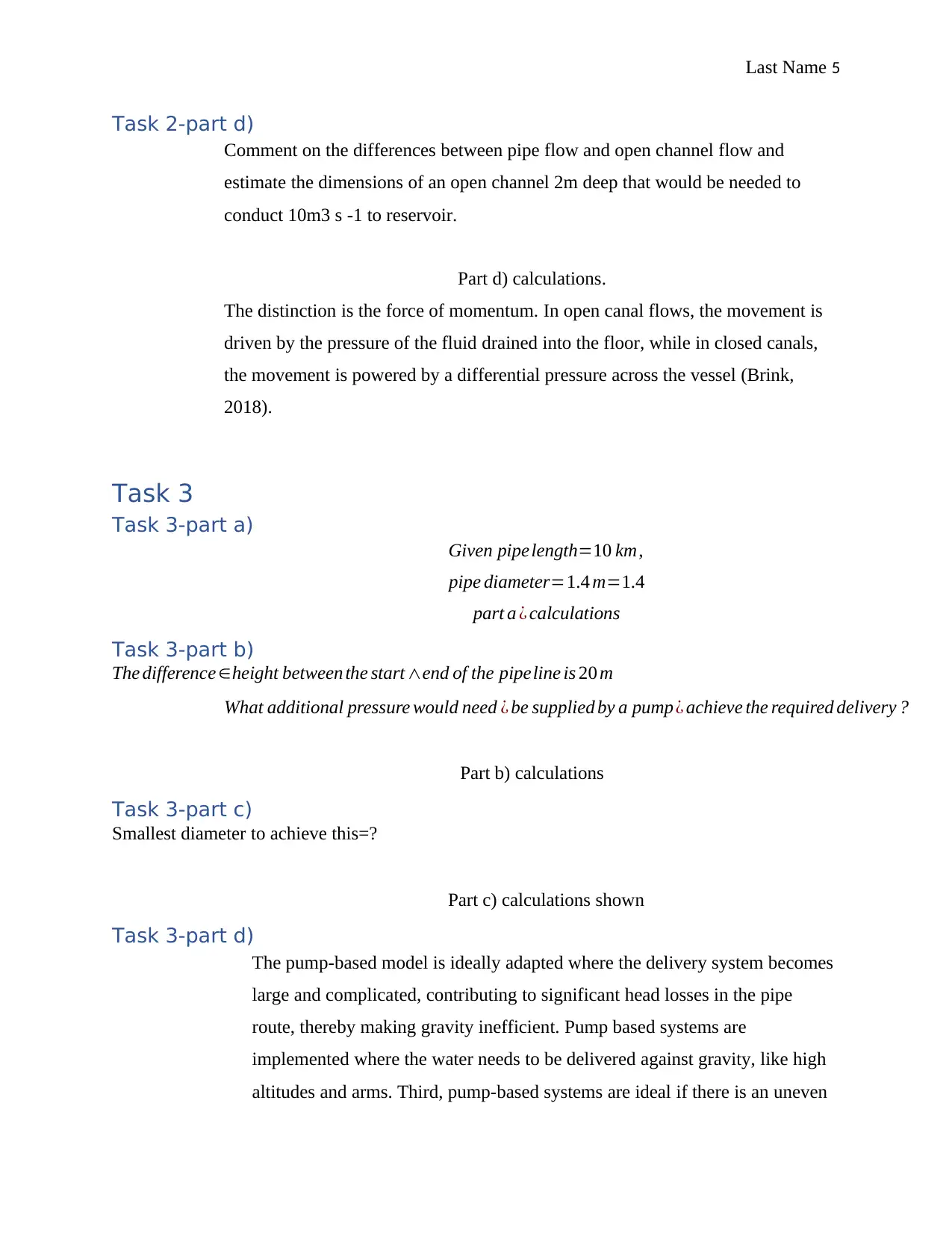
Task 2-part d)
Comment on the differences between pipe flow and open channel flow and
estimate the dimensions of an open channel 2m deep that would be needed to
conduct 10m3 s -1 to reservoir.
Part d) calculations.
The distinction is the force of momentum. In open canal flows, the movement is
driven by the pressure of the fluid drained into the floor, while in closed canals,
the movement is powered by a differential pressure across the vessel (Brink,
2018).
Task 3
Task 3-part a)
Given pipelength=10 km,
pipe diameter=1.4 m=1.4
part a ¿ calculations
Task 3-part b)
The difference ∈height between the start ∧end of the pipeline is 20 m
What additional pressure would need ¿ be supplied by a pump¿ achieve the required delivery ?
Part b) calculations
Task 3-part c)
Smallest diameter to achieve this=?
Part c) calculations shown
Task 3-part d)
The pump-based model is ideally adapted where the delivery system becomes
large and complicated, contributing to significant head losses in the pipe
route, thereby making gravity inefficient. Pump based systems are
implemented where the water needs to be delivered against gravity, like high
altitudes and arms. Third, pump-based systems are ideal if there is an uneven

Last Name 6
landscape and undulations, like the pipe network, are placed at varying levels
throughout the transmission network (Mory, 2013).
Gravity systems are more ideal if there is an even terrain to allow for pipe
network and structures with a standard rating to the point of distribution.
Second, gravity systems are ideally equipped where the water flow is not over
large stretches or lengths due to unavoidable head loss around the pipe parts,
curves and valves (White, 2017).
Task 4
Task 4-part a)
Given depth of ground water=1.5 m,
car park depth=9 m,
force on boundary walls?
Part a) calculations shown.
Task 4-part b)
Upon construction , the diaphragm wall can be used as the secure basement
retaining wall for the substructure . The diaphragm wall is commonly utilized∈building wher
obstacles ∈the ground prohibit the usage of sheet piles . Certain concerns such as the perception
of vibration (the installation of the diaphragm wall is often smoother than the building of the
sheet piles), the excavation of the earth and the disruption of the soil under the surrounding
current structures in the area of the site would therefore allow the diaphragm wall a more suitable
soil support structure (White, 2017).
In fact, the wall diaphragm is waterproof and could be built to handle both vertically and
horizontally loads. Diaphragm walls will therefore remove the need for bracing and strutting that
obstructs the building phase (Bird, 2012). The standard building technique for the diaphragm
wall is to create a trench that is partially protected by bentonite slurry. Once the foundation point
of the wall is achieved, the reinforcement enclosure is sunk to the trench. Concrete is then
pumped onto the trench using a tremie and displaces bentonite at the very same moment.
Task 4-part c)
A concrete slab renders the subfloor very rough , strong ,robust ∧sometimes very smooth . Tile
⊘ This is a preview!⊘
Do you want full access?
Subscribe today to unlock all pages.
Trusted by 1+ million students worldwide
Last Name 7
¿ stone flooringmay be built ¿
concrete , even thoughmost some flooring types need some
sort of underlaying∨a moisture shield imposed
concrete .Concrete basement floors are prone
¿ rain , whether through submersible drainage∨even ¿ surface humidity streaming into concrete
(not impermeable ¿ water∨water vapor ), therefore providing surface waterproofing. Vinyl
waterproofing would be the most suitable option in this scenario.
References
Bird, O. (2012) Science for engineering. Oxford, Newnes.
Brink, R. (2018) Hydraulics. Ede, MK Publishing.
Falkovich, G. (2018) Fluid mechanics. Cambridge, United Kingdom, Cambridge University Pres
s.
Fox, W. (2016) Fluid mechanics. Hoboken, NJ, Wiley.
Hibbeler, C. (2021) Fluid mechanics. Harlow, Essex, Pearson Education Limited.
Kariotoglou, P. & Psillos, D. (2019) Teaching and Learning Pressure and Fluids. Fluids. [Onlin
e] 4 (4), 194. Available from: doi:10.3390/fluids4040194.
Paraphrase This Document
Need a fresh take? Get an instant paraphrase of this document with our AI Paraphraser
Last Name 8
Kole, G. (2018) Basic Concepts in Fluid Mechanics. An Introduction to Fluid Mechanics and Tr
ansport Phenomena Fluid Mechanics and Its Applications. [Online] 5–10. Available from: doi:1
0.1007/978-1-4020-8537-6_1.
Landau, L.D. & Lifshit︠s︡ E. M. (2012) Fluid mechanics. Amsterdam, Elsevier Butterworth-Heine
mann.
Mory, M. (2013) Local Equations of Fluid Mechanics. Fluid Mechanics for Chemical Engineeri
ng. [Online] 1–28. Available from: doi: 10.1002/9781118617175.ch1.
White, M. (2017) Fluid mechanics. New Delhi, India, McGraw-Hill Education (India).
1 out of 8
Related Documents


Your All-in-One AI-Powered Toolkit for Academic Success.
+13062052269
info@desklib.com
Available 24*7 on WhatsApp / Email
![[object Object]](/_next/static/media/star-bottom.7253800d.svg)
Unlock your academic potential
Copyright © 2020–2026 A2Z Services. All Rights Reserved. Developed and managed by ZUCOL.