Unit 43 Hydraulics 1: Water Flow Analysis in Civil Engineering Systems
VerifiedAdded on 2022/08/12
|13
|2113
|50
Homework Assignment
AI Summary
This assignment delves into the principles of hydraulics within the context of civil engineering. It begins by examining water pressure in pipes and open channels, and then explores the forces of resistance to water flow, including viscosity and boundary layers, and how temperature affects these forces. The assignment then introduces the Reynolds number and its relationship to turbulent flow, and discusses the impact of surface roughness on boundary layers. Further, the assignment considers how to reduce water flow resistance in pipes and open channels, and outlines methods for increasing water supply to a growing town without disrupting existing systems. The assignment then continues by calculating the depth of flow in a canal system using the Manning equation and analyzing head loss using the Darcy-Weisbach equation. It investigates the feasibility of diverting excess water through a pipe, considering pressure differences and flow rates, and explores the differences between pipe and open channel flow, and the dimensions of an open channel. Finally, the assignment estimates head loss in a pipeline, calculates additional pressure requirements for a pump, and considers the impact of pipe diameter on flow. It concludes by discussing real-life factors that influence decisions between pipe-based and gravity-based water supply systems and analyzing the forces acting on the walls and floor of a below-ground car park due to groundwater, and discusses the materials and structures needed.
Unit 43 Hydraulics 1
HYDRAULICS FOR CIVIL ENGINEERING
By Name
Course
Instructor
Institution
Location
Date
HYDRAULICS FOR CIVIL ENGINEERING
By Name
Course
Instructor
Institution
Location
Date
Paraphrase This Document
Need a fresh take? Get an instant paraphrase of this document with our AI Paraphraser
Unit 43 Hydraulics 2
TASK 1
a) Water flowing in a pipe is taking water from a reservoir some 100m above a city what
is the pressure as it enters the city?
Pressure, P = Height x Density x Gravitational Force
= 100 x 1000x10
= 1,000,000 N/m2
= 10bar
If an open channel was to bring the water into the city from the same reservoir, what
would be the pressure be in the open channel. Explain briefly why.
The pressure in the open channel would also be zero since open channel flow is characterized
by a free surface which is exposed to the atmosphere hence the pressure remains constant
irrespective of any changes in flow velocity and water depth1.
b) What are the two major forces of resistance to water flow in pipes?
Viscosity: Viscosity is a type of frictional force that occur between the different fluid layers
which affect the way the fluid flows through the pipe.
Boundary layer: This is the fluid layer that sticks to the surface of pipe through which the fluid
speed decreases2.
c) How does the water temperature affect these forces?
1 Diamantis, M., Papageorgiou, M. & Kosmatopoulos, E., 2010. Identification and Adaptive Control for Open
Channel Water Flow Systems. Computer-Aided Civil and Infrastructure Engineering, Volume 26, pp. 464-480.
2 Zimmermann, A., 2010. Flow resistance in steep streams: An experimental study. Water Resources Research,
Volume 46.
Unit 43 Hydraulics 3
The temperature affects the density of water by decreasing the density when the temperature
increases and increasing the density when temperature decreases. By decreasing the density, the
viscosity and boundary layers are greatly reduced.
d) What is Reynolds Number and how is it related to turbulent flow?
The Reynolds number can be defined as a dimensionless quantity in fluid mechanics used in
predicting the patterns of flow in different situations of fluid flow. At high Reynolds number the
flow tend to be turbulent from differences in the direction and speed of fluids while at low
Reynolds numbers, flows tend to be laminar dominated3.
e) What is the boundary layer and how is it affected by the roughness of the surface over
which water is flowing?
A boundary layer can be defined as a relatively thin fluid layer close to the body surface that is
immersed in the fluid flow. The flow within the boundary layer may be turbulence flow or
streamline flow depending on the distance from the leading edge or particular problem.
If the surface over which water is flowing is smooth, water will have laminar boundary layer
flow since there is no skin friction drag resulting into smooth flow. If the surface over which
water is flowing is hydrodynamically rough over some section of the length there is development
of turbulent boundary layers which affects the mean defect profile and also skin friction4.
f) How is the resistance of water flow reduced either in a pipe or in an open channel?
3 Chamorro, L. & Arndt, R., 2011. Reynolds number dependence of turbulence statistics in the wake of
wind turbines. Wind Energy, Volume 15, pp. 733-742.
4 Widodo, E. & Pradhana, R., 2018. Analysis of pipe diameter variation in axial pumps for reducing head
loss. IOP Conference Series: Materials Science and Engineering, Volume 403\, p. 120.
⊘ This is a preview!⊘
Do you want full access?
Subscribe today to unlock all pages.

Trusted by 1+ million students worldwide
Unit 43 Hydraulics 4
The resistance of water flow either in a pipe or in an open channel can be reduced by:
i. Increasing the diameter of the pipe.
ii. Increasing the temperature of water to reduce the viscosity of water in the channel
iii. Reducing the length of the pipe
iv. Reducing the flow velocity in open channel5
g) The water supply to a rapidly expanding town was laid out many years ago when the
town was small and appeared to have a stable population. Outline how additional
supplies can be piped in without disrupting the current supplies.
Additional water supplies can be increased through subsequent increase of system pressure from
the source by increasing the flow rate. The system pressure should be higher or same value as the
pressure of additional supplies so as to avoid disrupting the current supplies.
Since Flow rate is given by: Q = P2−P1
R
Flow rate can be increased to match the additional supplies and current supplies by increasing
the pressure of supply, P2 to match with the current supply pressure P1.
TASK 2
5 Ercan, A. & Kavvas, L., 2013. Scaling and self-similarity in one-dimensional unsteady open channel flow.
Hydrological Processes, Volume 28, pp. 2721-2737.
Paraphrase This Document
Need a fresh take? Get an instant paraphrase of this document with our AI Paraphraser
Unit 43 Hydraulics 5
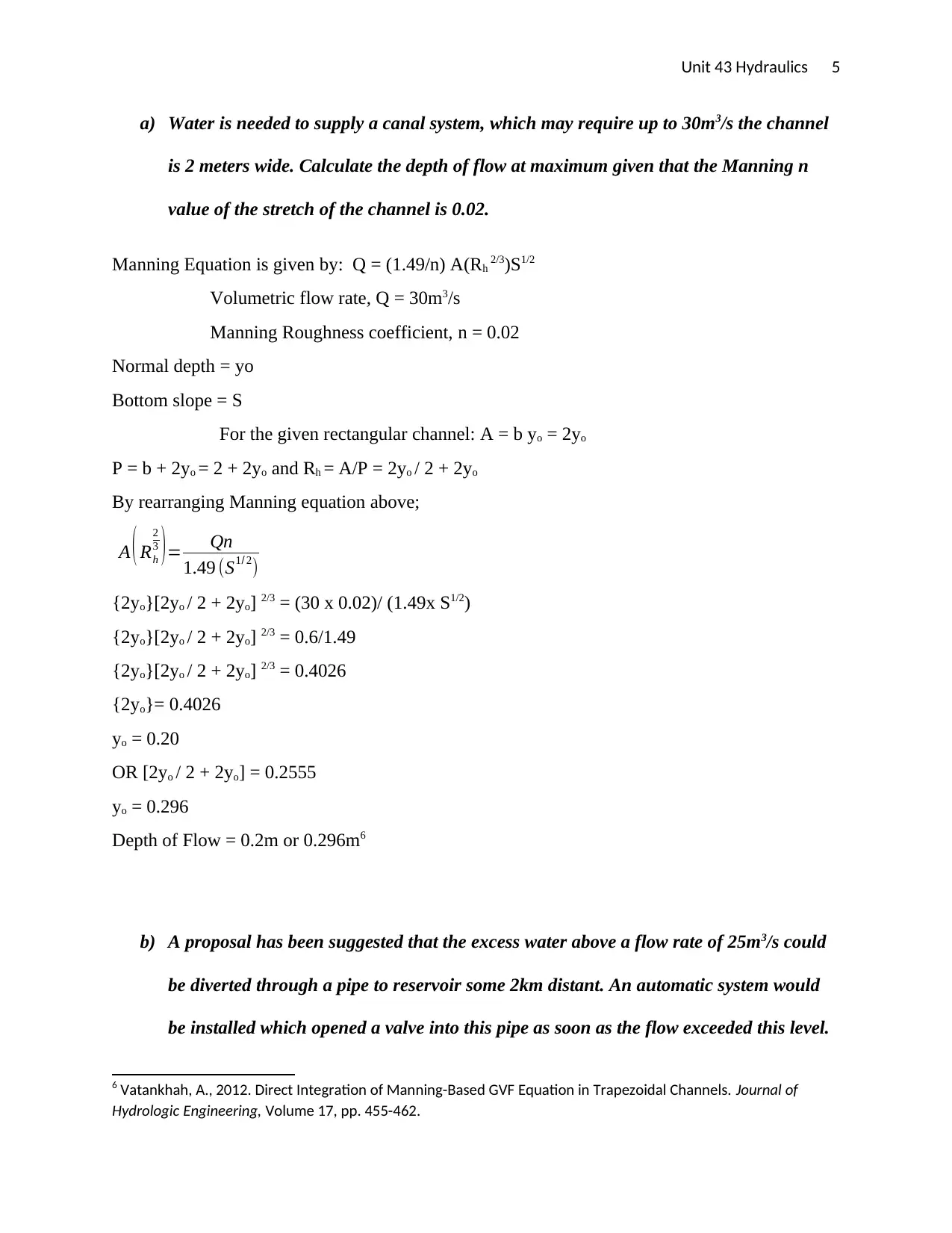
a) Water is needed to supply a canal system, which may require up to 30m3/s the channel
is 2 meters wide. Calculate the depth of flow at maximum given that the Manning n
value of the stretch of the channel is 0.02.
Manning Equation is given by: Q = (1.49/n) A(Rh 2/3)S1/2
Volumetric flow rate, Q = 30m3/s
Manning Roughness coefficient, n = 0.02
Normal depth = yo
Bottom slope = S
For the given rectangular channel: A = b yo = 2yo
P = b + 2yo = 2 + 2yo and Rh = A/P = 2yo / 2 + 2yo
By rearranging Manning equation above;
A ( Rh
2
3 )= Qn
1.49 (S1/ 2)
{2yo}[2yo / 2 + 2yo] 2/3 = (30 x 0.02)/ (1.49x S1/2)
{2yo}[2yo / 2 + 2yo] 2/3 = 0.6/1.49
{2yo}[2yo / 2 + 2yo] 2/3 = 0.4026
{2yo}= 0.4026
yo = 0.20
OR [2yo / 2 + 2yo] = 0.2555
yo = 0.296
Depth of Flow = 0.2m or 0.296m6
b) A proposal has been suggested that the excess water above a flow rate of 25m3/s could
be diverted through a pipe to reservoir some 2km distant. An automatic system would
be installed which opened a valve into this pipe as soon as the flow exceeded this level.
6 Vatankhah, A., 2012. Direct Integration of Manning-Based GVF Equation in Trapezoidal Channels. Journal of
Hydrologic Engineering, Volume 17, pp. 455-462.
Unit 43 Hydraulics 6
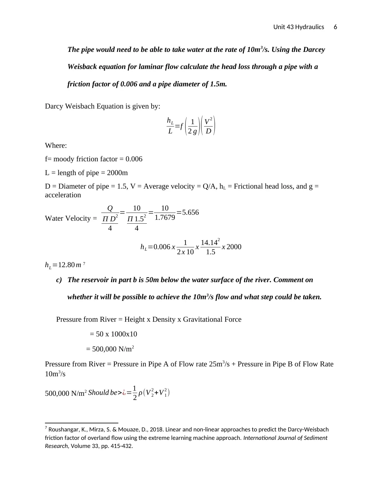
The pipe would need to be able to take water at the rate of 10m3/s. Using the Darcey
Weisback equation for laminar flow calculate the head loss through a pipe with a
friction factor of 0.006 and a pipe diameter of 1.5m.
Darcy Weisbach Equation is given by:
hL
L =f ( 1
2 g ) ( V 2
D )
Where:
f= moody friction factor = 0.006
L = length of pipe = 2000m
D = Diameter of pipe = 1.5, V = Average velocity = Q/A, hL = Frictional head loss, and g =
acceleration
Water Velocity =
Q
Π D2
4
= 10
Π 1.52
4
= 10
1.7679 =5.656
hL=0.006 x 1
2 x 10 x 14.142
1.5 x 2000
hL=12.80 m 7
c) The reservoir in part b is 50m below the water surface of the river. Comment on
whether it will be possible to achieve the 10m3/s flow and what step could be taken.
Pressure from River = Height x Density x Gravitational Force
= 50 x 1000x10
= 500,000 N/m2
Pressure from River = Pressure in Pipe A of Flow rate 25m3/s + Pressure in Pipe B of Flow Rate
10m3/s
500,000 N/m2 Should be>¿=1
2 ρ(V 2
2 +V 1
2 )
7 Roushangar, K., Mirza, S. & Mouaze, D., 2018. Linear and non-linear approaches to predict the Darcy-Weisbach
friction factor of overland flow using the extreme learning machine approach. International Journal of Sediment
Research, Volume 33, pp. 415-432.
⊘ This is a preview!⊘
Do you want full access?
Subscribe today to unlock all pages.

Trusted by 1+ million students worldwide
Unit 43 Hydraulics 7
500,000 N/m2 Should be>¿=1
2 x 1000(252+102)
¿ 362,500 N /m2
It is possible,
The valve will open and supply the reservoir with water since the pressure from the river is
sufficient to exceed to limit set by Flow rate of 25m3/s.
d) Comment on the differences between pipe flow and open channel flow and estimate the
dimensions of an open channel 2m deep that would be needed to conduct 10m3/s to
reservoir.
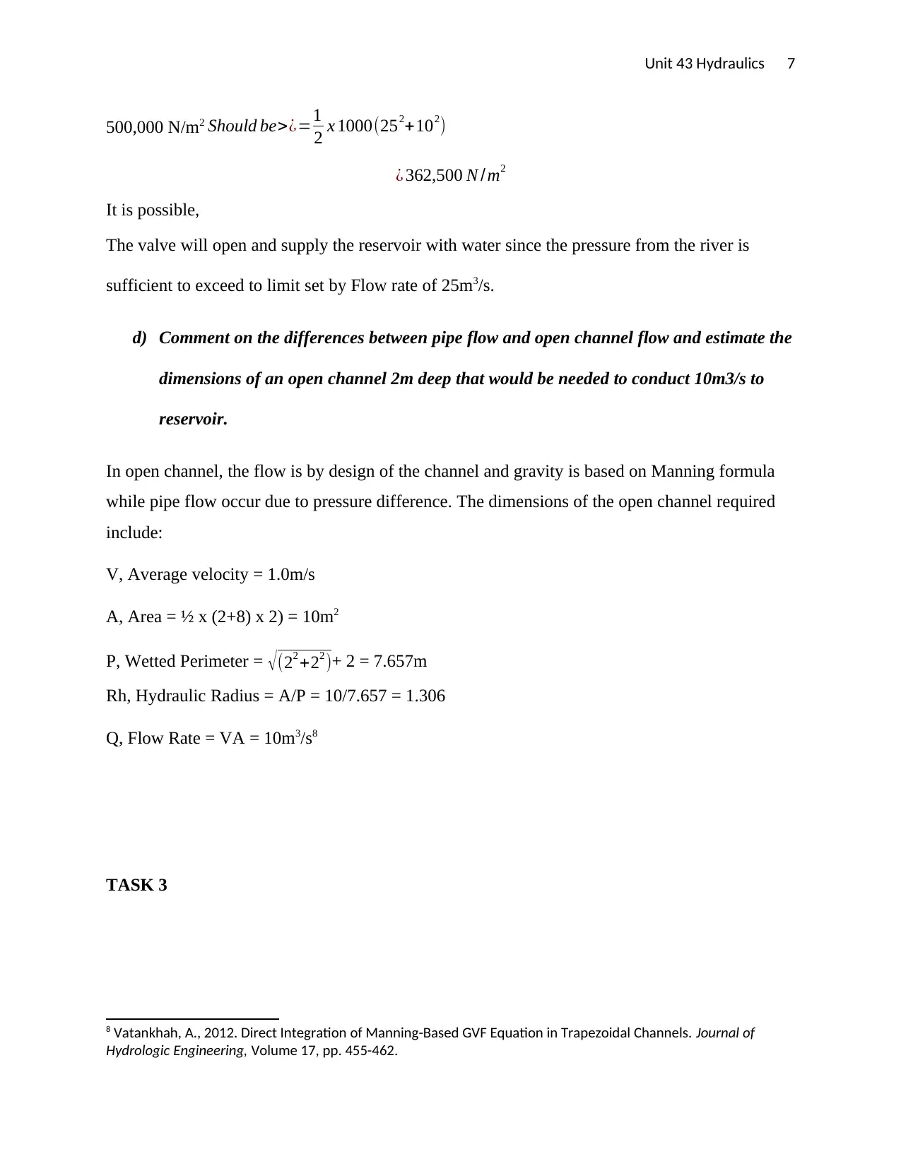
In open channel, the flow is by design of the channel and gravity is based on Manning formula
while pipe flow occur due to pressure difference. The dimensions of the open channel required
include:
V, Average velocity = 1.0m/s
A, Area = ½ x (2+8) x 2) = 10m2
P, Wetted Perimeter = √ (22 +22 )+ 2 = 7.657m
Rh, Hydraulic Radius = A/P = 10/7.657 = 1.306
Q, Flow Rate = VA = 10m3/s8
TASK 3
8 Vatankhah, A., 2012. Direct Integration of Manning-Based GVF Equation in Trapezoidal Channels. Journal of
Hydrologic Engineering, Volume 17, pp. 455-462.
Paraphrase This Document
Need a fresh take? Get an instant paraphrase of this document with our AI Paraphraser
Unit 43 Hydraulics 8
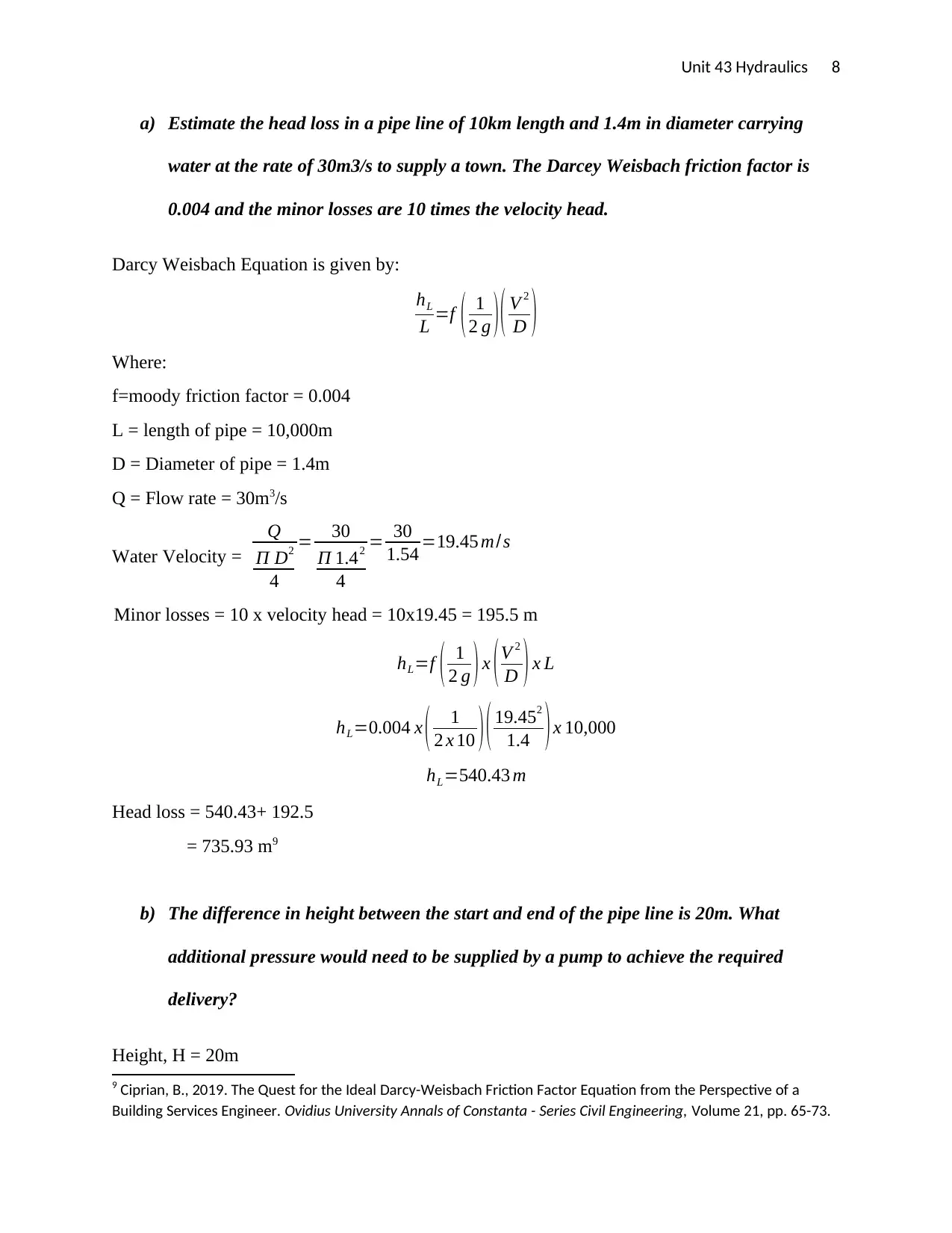
a) Estimate the head loss in a pipe line of 10km length and 1.4m in diameter carrying
water at the rate of 30m3/s to supply a town. The Darcey Weisbach friction factor is
0.004 and the minor losses are 10 times the velocity head.
Darcy Weisbach Equation is given by:
hL
L =f ( 1
2 g ) ( V 2
D )
Where:
f=moody friction factor = 0.004
L = length of pipe = 10,000m
D = Diameter of pipe = 1.4m
Q = Flow rate = 30m3/s
Water Velocity =
Q
Π D2
4
= 30
Π 1.42
4
= 30
1.54 =19.45 m/s
Minor losses = 10 x velocity head = 10x19.45 = 195.5 m
hL=f ( 1
2 g ) x (V 2
D ) x L
hL=0.004 x ( 1
2 x 10 ) ( 19.452
1.4 ) x 10,000
hL=540.43 m
Head loss = 540.43+ 192.5
= 735.93 m9
b) The difference in height between the start and end of the pipe line is 20m. What
additional pressure would need to be supplied by a pump to achieve the required
delivery?
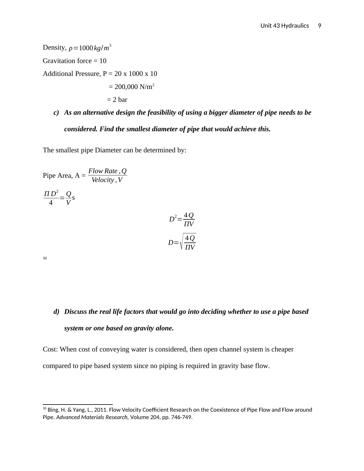
Height, H = 20m
9 Ciprian, B., 2019. The Quest for the Ideal Darcy-Weisbach Friction Factor Equation from the Perspective of a
Building Services Engineer. Ovidius University Annals of Constanta - Series Civil Engineering, Volume 21, pp. 65-73.
Unit 43 Hydraulics 9
Density, ρ=1000 kg/m3
Gravitation force = 10
Additional Pressure, P = 20 x 1000 x 10
= 200,000 N/m2
= 2 bar
c) As an alternative design the feasibility of using a bigger diameter of pipe needs to be
considered. Find the smallest diameter of pipe that would achieve this.
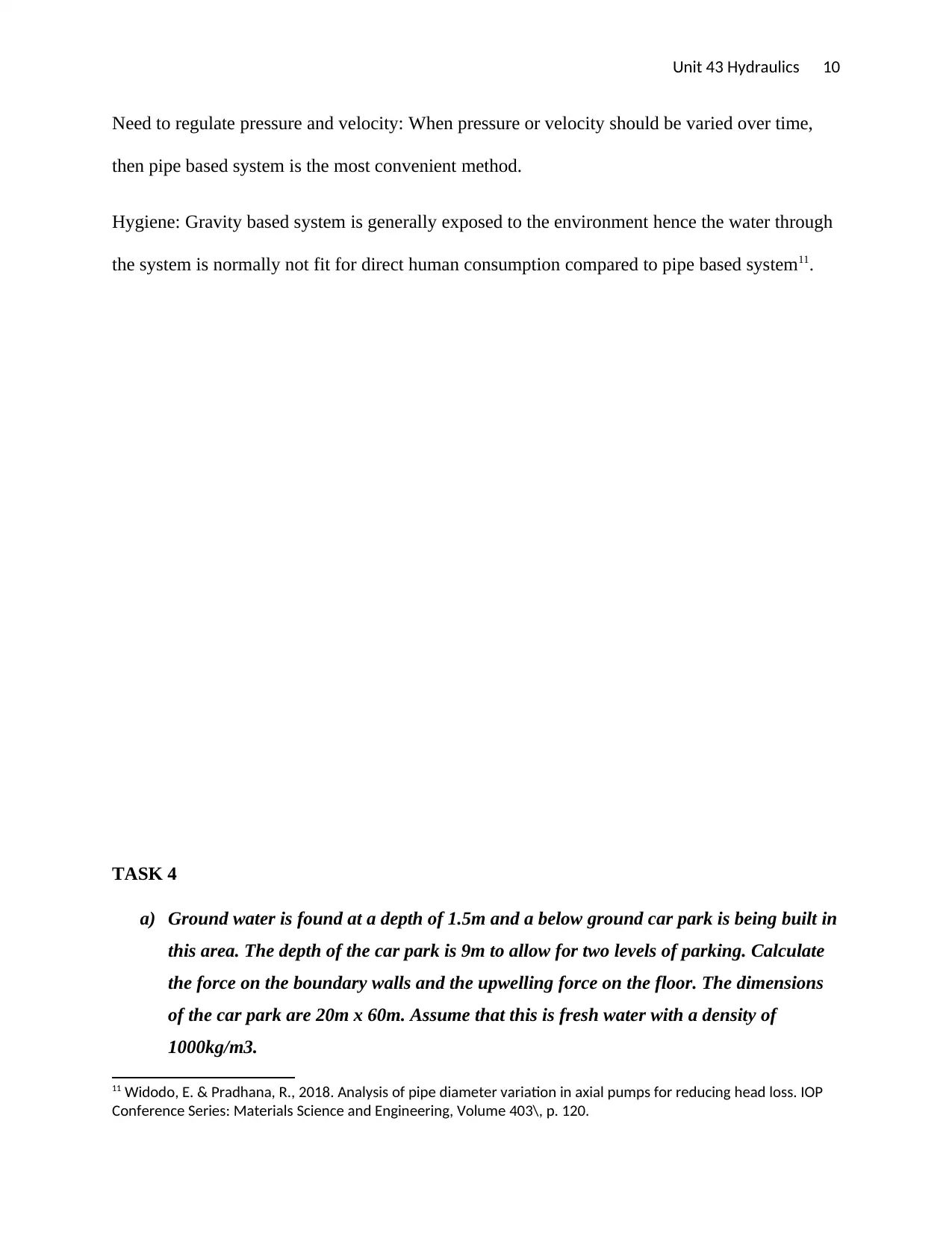
The smallest pipe Diameter can be determined by:
Pipe Area, A = Flow Rate , Q
Velocity , V
Π D2
4 = Q
V s
D2= 4 Q
ΠV
D= √ 4 Q
ΠV
10
d) Discuss the real life factors that would go into deciding whether to use a pipe based
system or one based on gravity alone.
Cost: When cost of conveying water is considered, then open channel system is cheaper
compared to pipe based system since no piping is required in gravity base flow.
10 Bing, H. & Yang, L., 2011. Flow Velocity Coefficient Research on the Coexistence of Pipe Flow and Flow around
Pipe. Advanced Materials Research, Volume 204, pp. 746-749.
⊘ This is a preview!⊘
Do you want full access?
Subscribe today to unlock all pages.

Trusted by 1+ million students worldwide
Unit 43 Hydraulics 10
Need to regulate pressure and velocity: When pressure or velocity should be varied over time,
then pipe based system is the most convenient method.
Hygiene: Gravity based system is generally exposed to the environment hence the water through
the system is normally not fit for direct human consumption compared to pipe based system11.
TASK 4
a) Ground water is found at a depth of 1.5m and a below ground car park is being built in
this area. The depth of the car park is 9m to allow for two levels of parking. Calculate
the force on the boundary walls and the upwelling force on the floor. The dimensions
of the car park are 20m x 60m. Assume that this is fresh water with a density of
1000kg/m3.
11 Widodo, E. & Pradhana, R., 2018. Analysis of pipe diameter variation in axial pumps for reducing head loss. IOP
Conference Series: Materials Science and Engineering, Volume 403\, p. 120.
Paraphrase This Document
Need a fresh take? Get an instant paraphrase of this document with our AI Paraphraser
Unit 43 Hydraulics 11
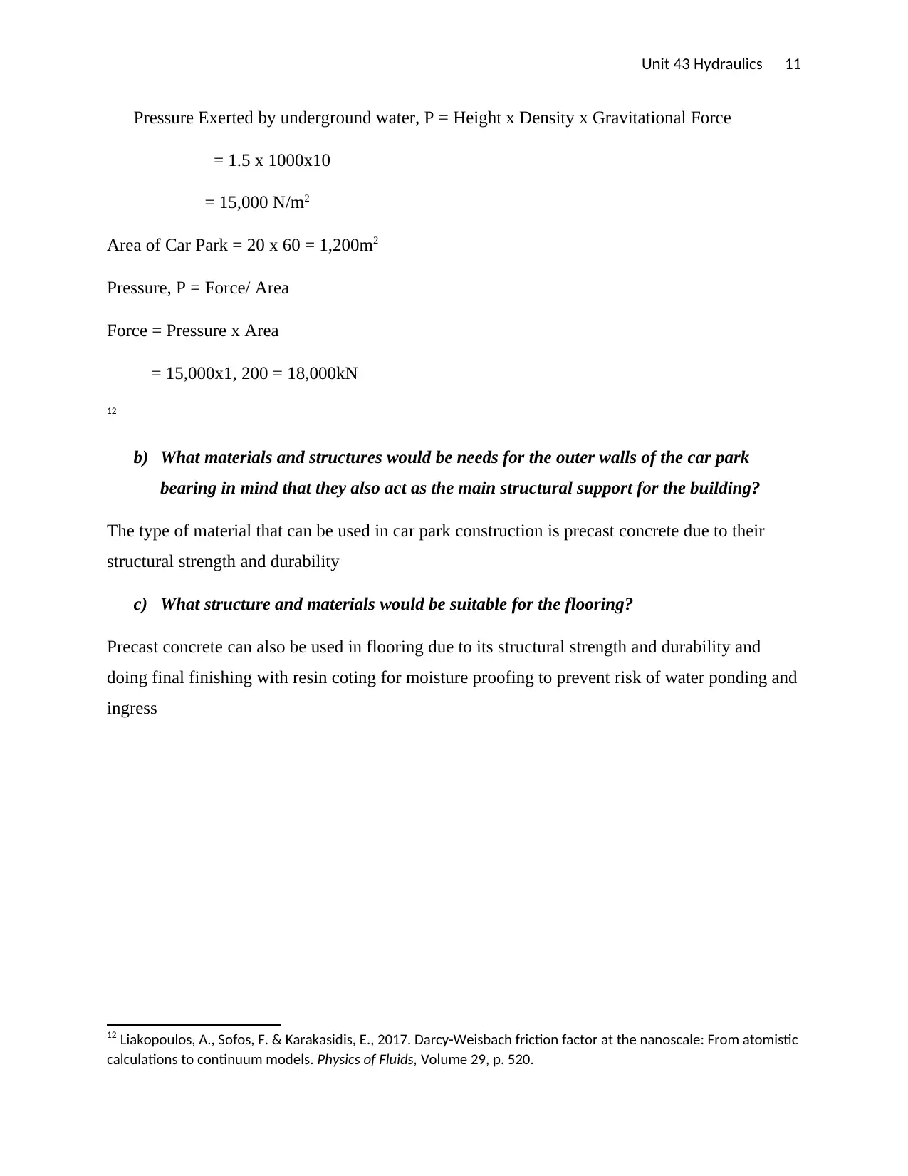
Pressure Exerted by underground water, P = Height x Density x Gravitational Force
= 1.5 x 1000x10
= 15,000 N/m2
Area of Car Park = 20 x 60 = 1,200m2
Pressure, P = Force/ Area
Force = Pressure x Area
= 15,000x1, 200 = 18,000kN
12
b) What materials and structures would be needs for the outer walls of the car park
bearing in mind that they also act as the main structural support for the building?
The type of material that can be used in car park construction is precast concrete due to their
structural strength and durability
c) What structure and materials would be suitable for the flooring?
Precast concrete can also be used in flooring due to its structural strength and durability and
doing final finishing with resin coting for moisture proofing to prevent risk of water ponding and
ingress
12 Liakopoulos, A., Sofos, F. & Karakasidis, E., 2017. Darcy-Weisbach friction factor at the nanoscale: From atomistic
calculations to continuum models. Physics of Fluids, Volume 29, p. 520.
Unit 43 Hydraulics 12
REFERENCES
Bing, H. & Yang, L., 2011. Flow Velocity Coefficient Research on the Coexistence of Pipe Flow and Flow
around Pipe. Advanced Materials Research, Volume 204, pp. 746-749.
Chamorro, L. & Arndt, R., 2011. Reynolds number dependence of turbulence statistics in the wake of
wind turbines. Wind Energy, Volume 15, pp. 733-742.
Ciprian, B., 2019. The Quest for the Ideal Darcy-Weisbach Friction Factor Equation from the Perspective
of a Building Services Engineer. Ovidius University Annals of Constanta - Series Civil Engineering, Volume
21, pp. 65-73.
Diamantis, M., Papageorgiou, M. & Kosmatopoulos, E., 2010. Identification and Adaptive Control for
Open Channel Water Flow Systems. Computer-Aided Civil and Infrastructure Engineering, Volume 26, pp.
464-480.
Ercan, A. & Kavvas, L., 2013. Scaling and self-similarity in one-dimensional unsteady open channel flow.
Hydrological Processes, Volume 28, pp. 2721-2737.
⊘ This is a preview!⊘
Do you want full access?
Subscribe today to unlock all pages.

Trusted by 1+ million students worldwide
1 out of 13
Related Documents
Your All-in-One AI-Powered Toolkit for Academic Success.
+13062052269
info@desklib.com
Available 24*7 on WhatsApp / Email
![[object Object]](/_next/static/media/star-bottom.7253800d.svg)
Unlock your academic potential
Copyright © 2020–2026 A2Z Services. All Rights Reserved. Developed and managed by ZUCOL.


