Construction Management Report: Pile, Basement, Outfall Details
VerifiedAdded on 2021/12/14
|10
|2078
|74
Report
AI Summary
This report analyzes key aspects of construction management, focusing on three main tasks. The first task examines pile construction, including scenarios necessitating pile foundations, types of piles (end-bearing piles), and the construction process involving pile drivers. The second task involves a hand drawing related to the project. The third task delves into basement construction, addressing issues such as wet basements, causes of water seepage, and waterproofing methods using bentonite. It details the application of bentonite panels and installation techniques. The report concludes by discussing the safe construction of outfalls, including headwall design, security screen requirements, and the use of flap valves to prevent backflow, adhering to relevant construction standards and safety protocols. The report references several sources for construction and engineering practices.
CONSTRUCTION MANAGEMENT
By Name
Course
Instructor
Institution
Location
Date
By Name
Course
Instructor
Institution
Location
Date
Paraphrase This Document
Need a fresh take? Get an instant paraphrase of this document with our AI Paraphraser
Task one A (Pile construction)
The first challenging problem that normally confronts the designer of any foundation is to
determine whether or not the conditions of the site are such that there is need for using the pile
system. The principle situation in which the piling system of the foundation may be needed have
been comprehensively illustrated. The most common cases that call for the use of the piling
system of the foundation is when the sub- soil is too much compressible or are just too weak to
provide support to the heavy vertical reactions. The transmission of the vertical reaction is from
the superstructure. In this particular case, the piles will serve as the extension of the columns or
the piers that aid in carrying the load to very deep substratum which is also very rigid. In cases
where such similar stratum does not exist, the transfer of the loads can be done gradually by the
system of the friction (Fernández, Torrens, Morales, and Martínez 2012).
The requirements for the use of the pile is because of the relative inability of the shallow footings
to aid in the transmission of the forces that are considered inclined and are basically
characterized by the overturning moments. Such situations are common features of the earth
retaining structures design with tall structures which are suspected to be subjected to high
earthquake or just very strong winds. The operation of the shaft is such that they resist the
upward forces by the use of the negative friction found around the shaft itself. The horizontal
forces are also getting resistance by either the vertical or the battered piles which normally
function as the structural system which combines the lateral resistance and the axial group of
forces (Tay, Panda, Paul, Noor, Tan and Leong 2017).
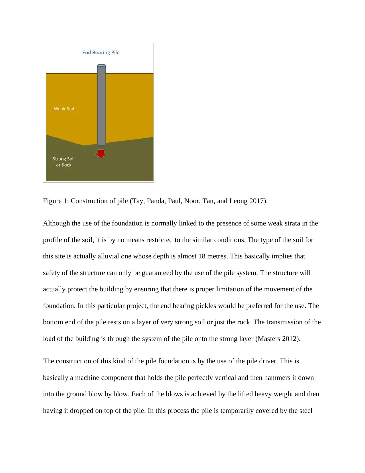
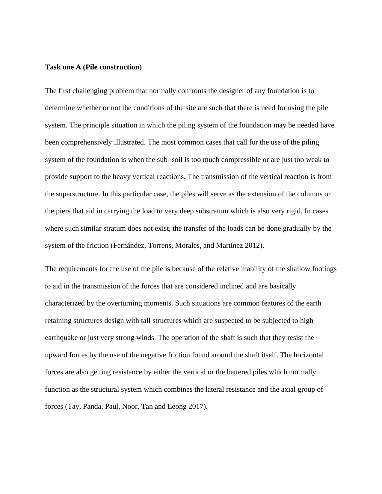
Figure 1: Construction of pile (Tay, Panda, Paul, Noor, Tan, and Leong 2017).
Although the use of the foundation is normally linked to the presence of some weak strata in the
profile of the soil, it is by no means restricted to the similar conditions. The type of the soil for
this site is actually alluvial one whose depth is almost 18 metres. This basically implies that
safety of the structure can only be guaranteed by the use of the pile system. The structure will
actually protect the building by ensuring that there is proper limitation of the movement of the
foundation. In this particular project, the end bearing pickles would be preferred for the use. The
bottom end of the pile rests on a layer of very strong soil or just the rock. The transmission of the
load of the building is through the system of the pile onto the strong layer (Masters 2012).
The construction of this kind of the pile foundation is by the use of the pile driver. This is
basically a machine component that holds the pile perfectly vertical and then hammers it down
into the ground blow by blow. Each of the blows is achieved by the lifted heavy weight and then
having it dropped on top of the pile. In this process the pile is temporarily covered by the steel
⊘ This is a preview!⊘
Do you want full access?
Subscribe today to unlock all pages.
Trusted by 1+ million students worldwide
cap that prevents it from the disintegration. The pile driver thus serves to perform two functions:
It will act as a crane that lifts the pile from the horizontal position from the ground and rotates it
into the vertical position. Secondly; it hammers the pile down the ground.
Figure 2: Pile construction (Masters 2012).
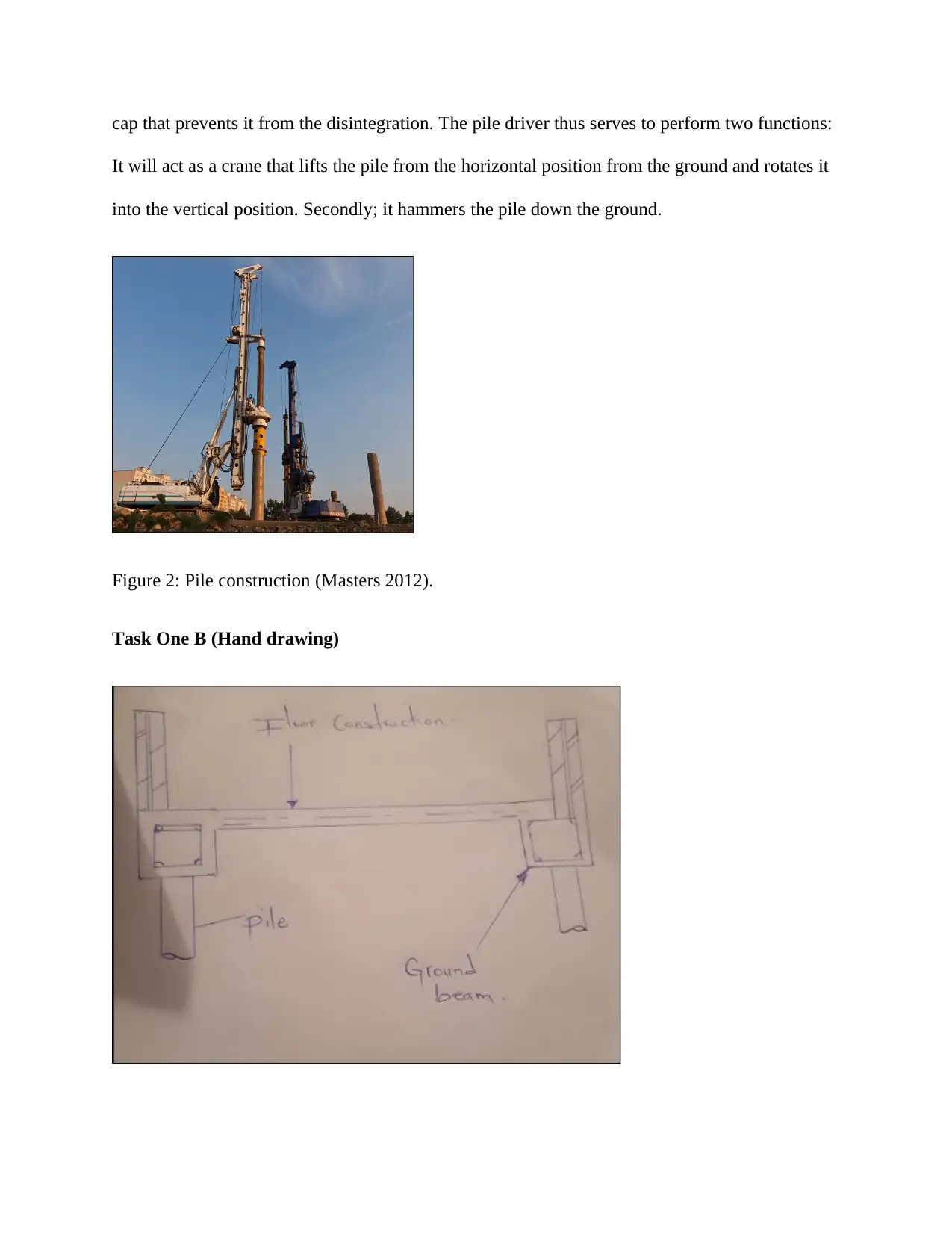
Task One B (Hand drawing)
It will act as a crane that lifts the pile from the horizontal position from the ground and rotates it
into the vertical position. Secondly; it hammers the pile down the ground.
Figure 2: Pile construction (Masters 2012).
Task One B (Hand drawing)
Paraphrase This Document
Need a fresh take? Get an instant paraphrase of this document with our AI Paraphraser
Figure 3: Complete system (Masters 2012)
Task One C (Basement Construction)
The most common complaints from the owners of the structures are the presence of the wet
basement. There are several causes of the wet basement including damp and the leaky
basements. As the water table becomes closer to the surface, the more severe the condition. As
the time progresses, the walls of the basement may develop serious cracks and this may possible
act as the potential seepages of the water. The other common source of the water seepage that
causes the wet basement is the weak joint between the floor and the wall. The form ties that are
left on the wall will definitely rust and let the water seep around them. Poor construction means
that leaves the honey combs and the old joints may also results into the adverse effects of the wet
basements. In order to ensure that the waterproof system of the construction is avoided, the
construction should be done immediately after the removal of the forms. A dry basement
therefore starts with a good wall and a good floor that is made of the quality concrete (Lu, Cui
and Li 2016).
The most successful water proof basement construction will make use of the bentonite.Bentonite
is basically rare fine grained clay that has been in the construction industry for very may years in
the swampy areas. When water comes into contact with the surface grain of this compound, it
swells up to 15 times their initial dry volume. When they are applied to the exterior surface of
the constructed wall, they keep the moisture out permanently. This compound will therefore be
sandwiched between the cardboards and even as the cardboards deteriorate, the compound will
remain relatively stable. It will stay active indefinitely dying as the surrounding earth dries up
and springs into action when the surrounding becomes wet again.
The panel will be cemented onto the outside of the wall of the basement by the use of the mastic.
Alternatively they will be nailed for a proper use. Regardless of the method used, the
requirements are holding exercise up to the point where the excavation is backfilled. The method
of the nailing is normally preferred considering that it is cleaner and also faster. These panels are
placed on the footing where they stand vertically. Length of the wood lath is placed over the joint
that is the region between the upper and the lower row of the panel. The blueth lath nails are then
driven passed the lower panels into the concrete that is regarded green. For the case of the upper
panel, it is slipped into the space without process of nailing has been indicated below. The holes
that are present inside the panel are considered as the likelihood of letting the bentonite sifting
out of the broken corrugations (Hakim 2013).
This leads to the effects of leaving the holes open. Considering that it is only the upper surface
that will be nailed, the impacts will not be that much serious. The first row of the panel will be
used in covering the bottom from approximate height of the 4 feet from the foundation. The
panels are folded simply so as to go round the edges that are regarded as the compulsory corners.
The portion that sticks above the recommended height will definitely fall down thereby adding
extended protection to the level grade (Holt and Goulding 2014). The bulk bentonite is poured in
order to form a 3-inch cover all round where the wall and the footing meet. The installation
should be done at the time when the footing system is still exposed.
⊘ This is a preview!⊘
Do you want full access?
Subscribe today to unlock all pages.
Trusted by 1+ million students worldwide
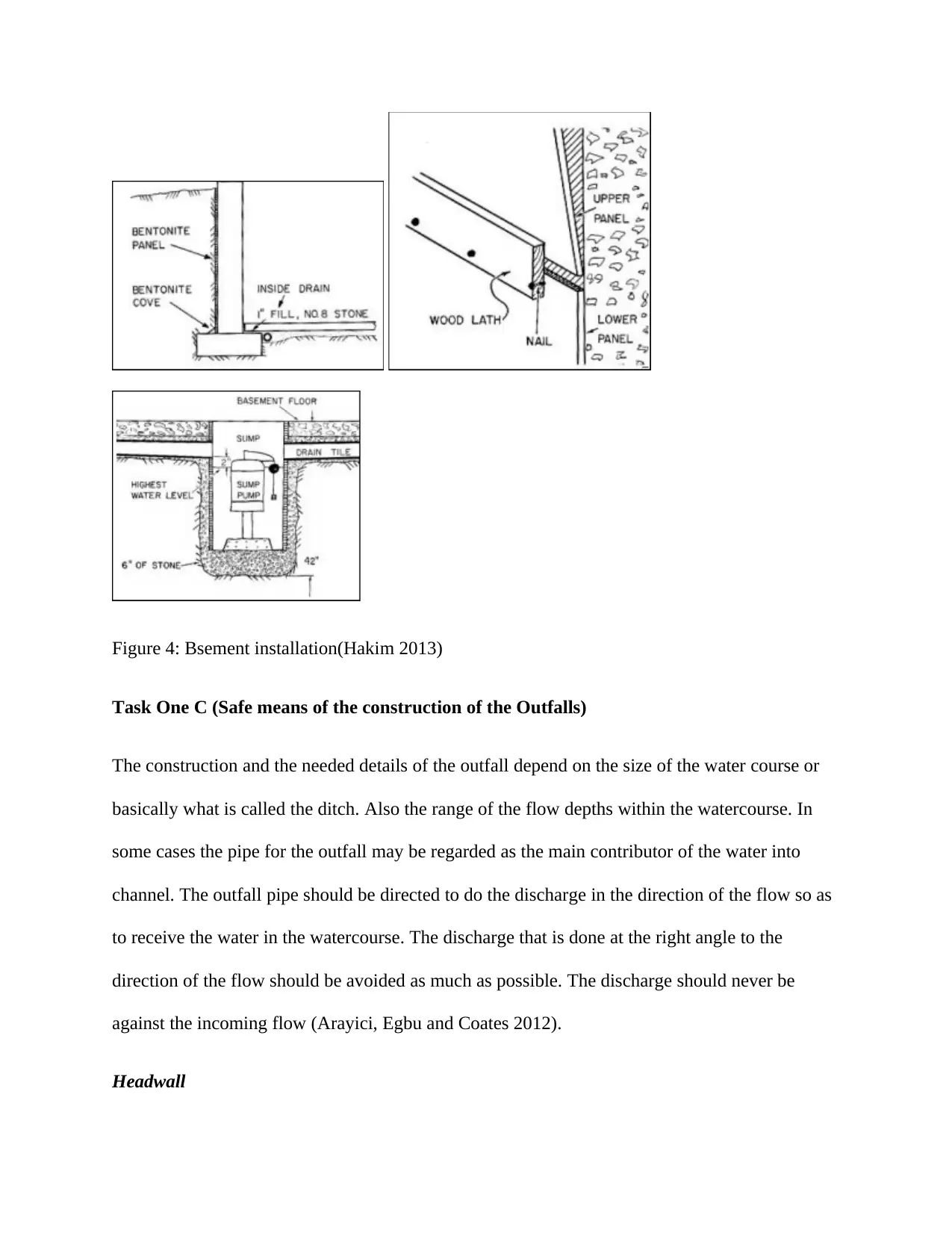
Figure 4: Bsement installation(Hakim 2013)
Task One C (Safe means of the construction of the Outfalls)
The construction and the needed details of the outfall depend on the size of the water course or
basically what is called the ditch. Also the range of the flow depths within the watercourse. In
some cases the pipe for the outfall may be regarded as the main contributor of the water into
channel. The outfall pipe should be directed to do the discharge in the direction of the flow so as
to receive the water in the watercourse. The discharge that is done at the right angle to the
direction of the flow should be avoided as much as possible. The discharge should never be
against the incoming flow (Arayici, Egbu and Coates 2012).
Headwall
Paraphrase This Document
Need a fresh take? Get an instant paraphrase of this document with our AI Paraphraser
The location of the outfall in relation to the top water level that receives the watercourse shall be
in accordance with the NRAHD33.In the cases where the velocity of the outfall pipe is actually
in excess of 1.0m/then there will be requirement of some form of the dissipation of the energy.
The design of the outfall should actually be checked to ensure that the velocities of the peak
discharge do not exceed 2.5m/sin order to prevent the effects of the erosions, the headwalls
should be keyed into the banks and bed. This will reduce the effects of the scour that undermines
the structure. The construction of the headwall should be in accordance with the series 500 of the
NRA.
Security Screens
Considering that the diameter of the pipe is 700mm which is far much greater than 375mm, there
is need to fit the security screen. The screen should be made of the mild steel sections that are
flat welded. The position of the screen will be in such a way that the maximum angle to the
horizontal is 60 degrees preferable at 45 degrees (Zabihi, Habib and Mirsaeedie 2012). She will
be provision of the flat section screen at the top which basically facilitates clearing process. The
locking nuts should be used in the securing of the screen to the headwalls.
Flap valves that serve to prevent the backflow of the water from the element that receives the
water course into the systems of the drainage. The presence of this valve normally causes
significant head loss to the discharge flow hence reduction of the capacity of the latter section of
the system. Considering that this particular outfall will be accessible to the members of the
public, the plastics valves should be used instead of the cast since they are less susceptible to
vandalism.
REFERENCES
Fernández Carrasco, L., Torrens Martín, D., Morales, L.M. and Martínez Ramírez, S.,
2012. Infrared spectroscopy in the analysis of building and construction materials (pp. 357-372).
InTech.
Tay, Y.W.D., Panda, B., Paul, S.C., Noor Mohamed, N.A., Tan, M.J. and Leong, K.F., 2017. 3D
printing trends in building and construction industry: a review. Virtual and Physical
Prototyping, 12(3), pp.261-276.
Masters, L.W. ed., 2012. Problems in service life prediction of building and construction
materials (Vol. 95). Springer Science & Business Media.
Lu, Y., Cui, P. and Li, D., 2016. Carbon emissions and policies in China's building and
construction industry: evidence from 1994 to 2012. Building and Environment, 95, pp.94-103.
Hakim, B.S., 2013. Arabic Islamic Cities Rev: Building and Planning Principles. Routledge.
Holt, G. and S. Goulding, J., 2014. Conceptualisation of ambiguous-mixed-methods within
building and construction research. Journal of Engineering, Design and Technology, 12(2),
pp.244-262.
Zabihi, H., Habib, F. and Mirsaeedie, L., 2012. Sustainability in building and construction:
revising definitions and concepts. International Journal of Emerging Sciences, 2(4), pp.570-579.
Arayici, Y., Egbu, C.O. and Coates, S.P., 2012. Building information modelling (BIM)
implementation and remote construction projects: issues, challenges, and critiques. Journal of
Information Technology in Construction, 17, pp.75-92.
⊘ This is a preview!⊘
Do you want full access?
Subscribe today to unlock all pages.
Trusted by 1+ million students worldwide

1 out of 10


Your All-in-One AI-Powered Toolkit for Academic Success.
+13062052269
info@desklib.com
Available 24*7 on WhatsApp / Email
![[object Object]](/_next/static/media/star-bottom.7253800d.svg)
Unlock your academic potential
Copyright © 2020–2026 A2Z Services. All Rights Reserved. Developed and managed by ZUCOL.