Solution for Civil Engineering Structural Analysis Assignment
VerifiedAdded on 2022/11/24
|15
|1161
|108
Homework Assignment
AI Summary
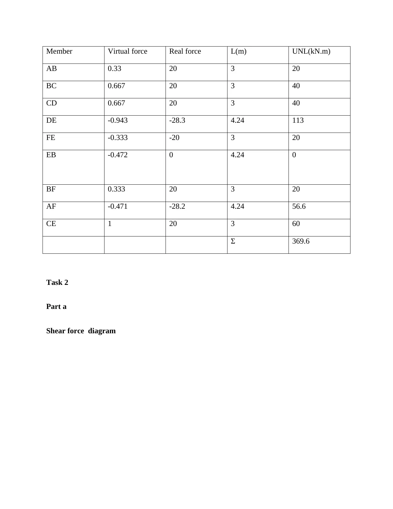
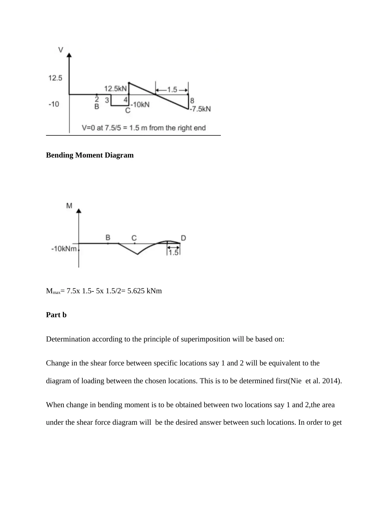
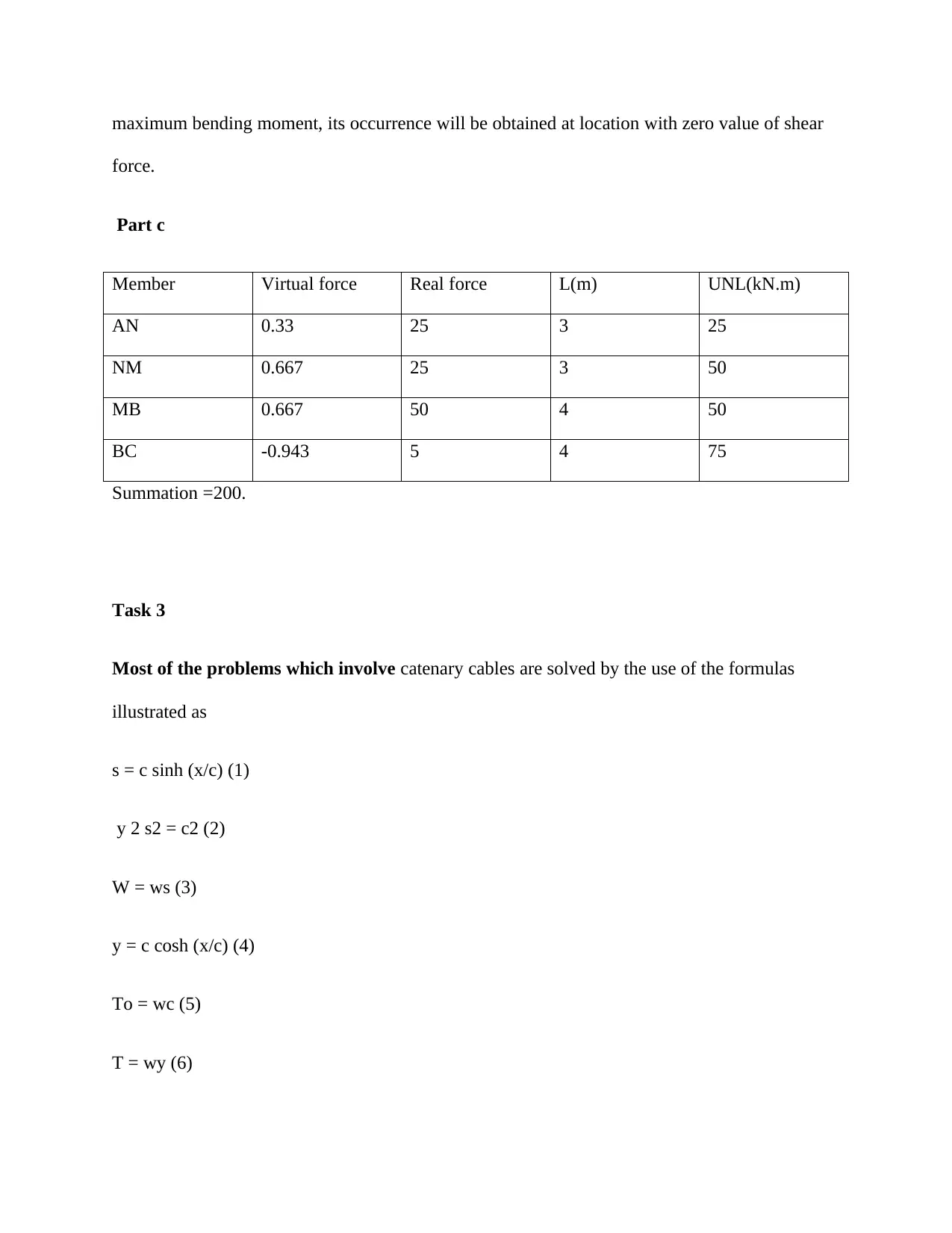
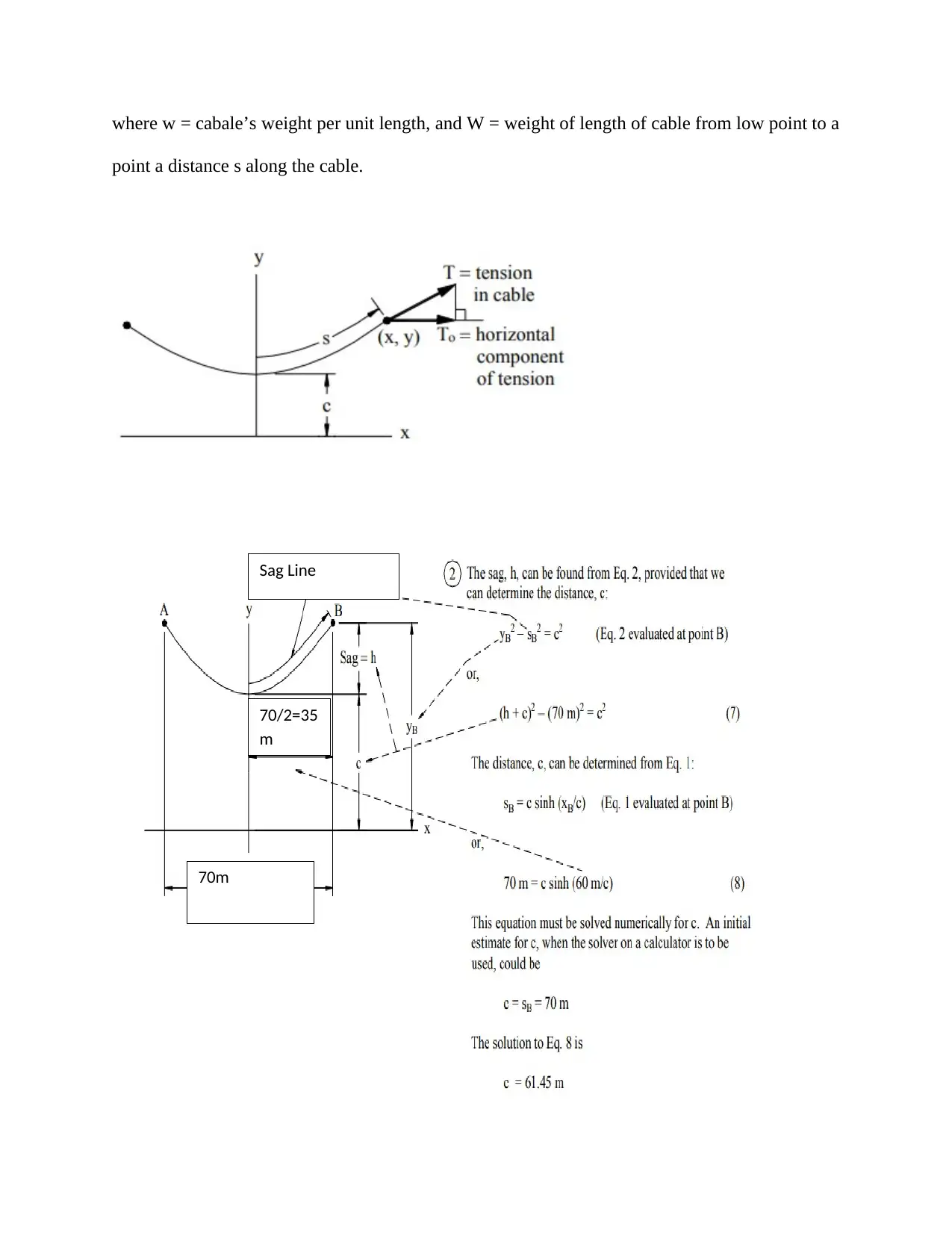
This civil engineering assignment solution covers a range of structural analysis problems. Task 1 focuses on truss analysis, determining reactions, and identifying indeterminate degrees and stability. Task 2 involves shear force and bending moment diagrams, with calculations and explanations using the principle of superposition. Task 3 delves into catenary cable analysis, providing formulas and calculations for sag. Finally, Task 4 analyzes an arch structure, calculating reactions and internal forces within its members. The solution includes detailed calculations, diagrams, and references to relevant engineering concepts and principles, making it a valuable resource for students studying structural engineering.

CIVIL ENGINEERING
By Name
Course
Instructor
Institution
Location
Date
By Name
Course
Instructor
Institution
Location
Date
Paraphrase This Document
Need a fresh take? Get an instant paraphrase of this document with our AI Paraphraser

Task 1
Part a
Calculations of the number of reactions:
R=2rhinge
When 2 is substituted for rhinge
R=2x2
=4
When 4 is substituted for the value of r,21 for n and 38 for b,then
r+b>2n
4+38>(2x21)
42>42.
Also, 4+10-(2x6)
=2
The truss is therefore indeterminate to degree 2.
Considering that the reaction in the members of the link pass through the left hinge which
translates to the concurrent force system, the truss is therefore unstable geometrically.
By using the truss sample which has been shared above, the structure will be capable of carrying
vertical load as it had been designed to do. It is however important to note that the stability of the

truss against lateral movement has not been ensured yet(Eskandari and Korouzhdeh 2016). The
chords of the compression will tend to buckle in the direction which is perpendicular to the
truss’s plane. Besides, wind loads will also exert forces which are perpendicular to the plane of
the truss. The corrective for this particular problem will be to use the system of bracing. Battens
and purlins may be used as part of the lateral bracing system. During the process of bracing, at
least each point of the panel will be braced out of the movement plane. X-bracing in the plane
will be added to form a system which is structurally sound(Kala 2013).
Part b
.
Starting with joint C. The Equilibrium at joint C Applying Lami's theorem
⊘ This is a preview!⊘
Do you want full access?
Subscribe today to unlock all pages.

Trusted by 1+ million students worldwide

Joint B has three unknown force. So we select joint D, which has only two unknown forces .
Paraphrase This Document
Need a fresh take? Get an instant paraphrase of this document with our AI Paraphraser

Now joint E has 3 unknown and joint B has two unknown now we select joint B.
Resolving the forces in vertical dedication
Therefore, the actual direction is opposite to that show.
Hence,
Resolving the forces in vertical dedication
Therefore, the actual direction is opposite to that show.
Hence,

Coming to point E now,
Resoling the forces in vertical direction
Method of section
.
Resoling the forces in vertical direction
Method of section
.
⊘ This is a preview!⊘
Do you want full access?
Subscribe today to unlock all pages.

Trusted by 1+ million students worldwide

To solve it, take a section passing through three members HG, CG and CD. Taking left
hand side for making free-body diagram, we observe that there are three unknown forces.
We have three equilibrium equations:
∑FX =0 ∑FY =0 and ∑M =0
Utilizing first equilibrium equation, i.e., resolving all external forces on the left part in the
horizontal directon and making their algebraic sum equal to zero.
F1 + F2 cos 450 +F3 =0..............(A)
Paraphrase This Document
Need a fresh take? Get an instant paraphrase of this document with our AI Paraphraser

Smilarly, vertical force balance gives
F2 sin 450 -100=0
which gives,
F2 =100√2 =141.4 kN
Lastly taking moment about, point C,
-F1 × 1 + 100 × 2 =0
F1 = 200kN
Equating (A) thus gives
200+ 100+F3 =0
F3 = -300kN
Compression members will include the following:
BH,CI,DJ,EK,FL
Tension Members ill include the following:
AB,BC,CD,DE,EF,FG,GH,HI,IJ,JK,KL, and LM.
Part c
Virtual Work

Member Virtual force Real force L(m) UNL(kN.m)
AB 0.33 20 3 20
BC 0.667 20 3 40
CD 0.667 20 3 40
DE -0.943 -28.3 4.24 113
FE -0.333 -20 3 20
EB -0.472 0 4.24 0
BF 0.333 20 3 20
AF -0.471 -28.2 4.24 56.6
CE 1 20 3 60
Σ 369.6
Task 2
Part a
Shear force diagram
AB 0.33 20 3 20
BC 0.667 20 3 40
CD 0.667 20 3 40
DE -0.943 -28.3 4.24 113
FE -0.333 -20 3 20
EB -0.472 0 4.24 0
BF 0.333 20 3 20
AF -0.471 -28.2 4.24 56.6
CE 1 20 3 60
Σ 369.6
Task 2
Part a
Shear force diagram
⊘ This is a preview!⊘
Do you want full access?
Subscribe today to unlock all pages.

Trusted by 1+ million students worldwide

Bending Moment Diagram
Mmax= 7.5x 1.5- 5x 1.5/2= 5.625 kNm
Part b
Determination according to the principle of superimposition will be based on:
Change in the shear force between specific locations say 1 and 2 will be equivalent to the
diagram of loading between the chosen locations. This is to be determined first(Nie et al. 2014).
When change in bending moment is to be obtained between two locations say 1 and 2,the area
under the shear force diagram will be the desired answer between such locations. In order to get
Paraphrase This Document
Need a fresh take? Get an instant paraphrase of this document with our AI Paraphraser

maximum bending moment, its occurrence will be obtained at location with zero value of shear
force.
Part c
Member Virtual force Real force L(m) UNL(kN.m)
AN 0.33 25 3 25
NM 0.667 25 3 50
MB 0.667 50 4 50
BC -0.943 5 4 75
Summation =200.
Task 3
Most of the problems which involve catenary cables are solved by the use of the formulas
illustrated as
s = c sinh (x/c) (1)
y 2 s2 = c2 (2)
W = ws (3)
y = c cosh (x/c) (4)
To = wc (5)
T = wy (6)

where w = cabale’s weight per unit length, and W = weight of length of cable from low point to a
point a distance s along the cable.
70m
70/2=35
m
Sag Line
point a distance s along the cable.
70m
70/2=35
m
Sag Line
⊘ This is a preview!⊘
Do you want full access?
Subscribe today to unlock all pages.

Trusted by 1+ million students worldwide
1 out of 15

Your All-in-One AI-Powered Toolkit for Academic Success.
+13062052269
info@desklib.com
Available 24*7 on WhatsApp / Email
Unlock your academic potential
Copyright © 2020–2025 A2Z Services. All Rights Reserved. Developed and managed by ZUCOL.