Civil Engineering Technology Report: Earthwork and Safety
VerifiedAdded on  2022/08/24
|26
|4123
|49
Report
AI Summary
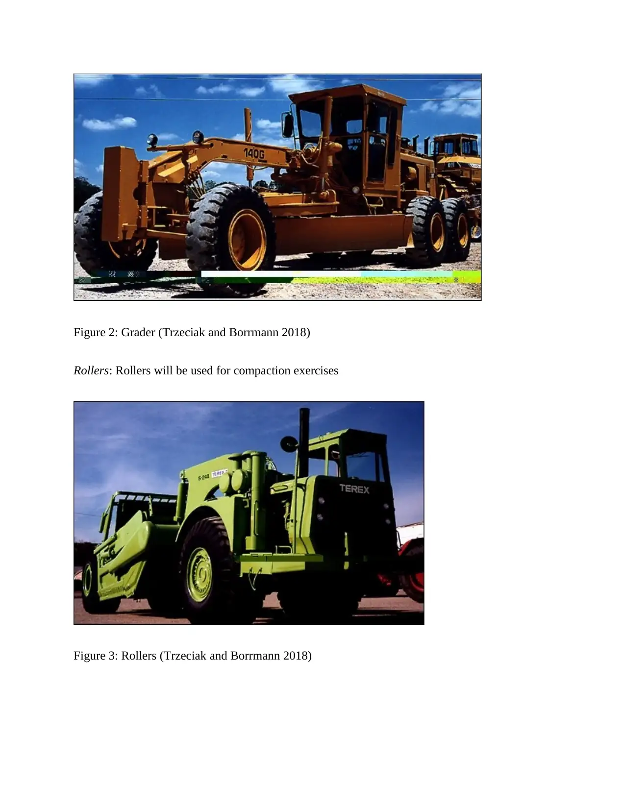
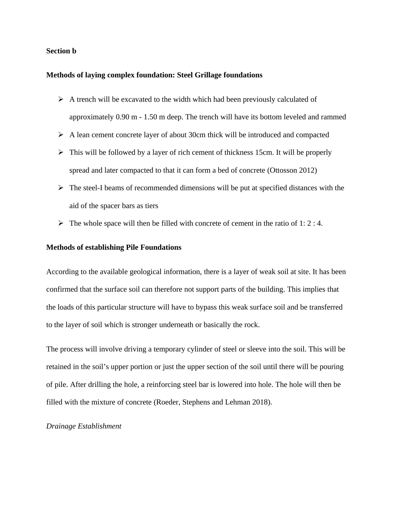
This civil engineering technology report addresses earthwork activities, including excavation, filling, and compaction techniques. It details methods for measuring volumes and the equipment used, such as bulldozers, excavators, and rollers. The report also examines complex foundation methods like steel grillage and pile foundations, considering geological challenges. Furthermore, it covers drainage establishment, culvert and underpass construction, and basement excavation techniques. The report emphasizes construction site hazards, risk assessments, and safety plans, including health and safety legislation. Finally, it explores geological, quality, and environmental problems, proposing solutions to minimize vibrations, address quality issues, and mitigate noise and air pollution. This comprehensive report offers a detailed analysis of various aspects of civil engineering technology.

CIVIL ENGINEERING TECHNOLOGY
By Name
Course
Instructor
Institution
Location
Date
By Name
Course
Instructor
Institution
Location
Date
Secure Best Marks with AI Grader
Need help grading? Try our AI Grader for instant feedback on your assignments.

Introduction
Earthwork involves the process of removal after loosening as well as handling of quantities of
the earth during the process of construction. In this particular scenario, the activities or
operations of earthwork will be carried out so that a level terrace can be obtained or established.
The level surface is commonly refered to as the bench.
TASK 1
Section a
Earthwork Activities
In most cases, the operations of the earthwork will be performed so that longitudinal slope is
obtained. Such kind of the surfaces will allow for the establishment or building of camber as well
as drainages. In order to come up with the industrial units as per the demands of the client, the
following primary activities of earthworks will be performed:
 Measurement as well as calculations of the excavated volumes
 Excavation activities which will include cutting to cross fill, leveling, borrow excavation
and finally U-cut
 Hauling, loading and finally unloading
 Filling: Majorly includes compaction after spreading
Techniques to be used
In order to effectively measure the volumes excavated accurately, the following techniques are
likely to be employed:

Use of the traditional methods of taking level measurements with the right instruments. This will
then be followed by drawing to scale the cross-section. This will then allow for the calculation
of the volumes (Lawson 2005).
Alternatively, there will be use of the slotting techniques. This technique allows for the
measurements to be taken by the use of tape or ruler on the cut itself. This particular technique
will be preferred since it can be used elaborately without the need of equipment for the survey. It
will involve excavation of the soil to about 0.3-1.0 metre wide slots. This will be done at right
angles in relation to the centre-line up to the level which has been predetermined.
Earthmoving Equipment
The following equipment will be used in the processes of earthworks:
Bulldozer-This will be used basically for soil pushing
Drag Line-This type of vehicle usually allow for the excavation to be done its own level. In most
of the cases, it is just a bucket with one end made up of a jib. It will be solely used for bulk
excavation. This is due to the fact that it is uncontrolled at times.
Dump Truck-They are wheeled vehicles which are capable of moving fast. They will be used for
the material transfer from one point of the site to the other.

Figure 1: Dump Truck (Trzeciak and Borrmann 2018)
Shovels-These are also wheeled vehicles that assist in filling up of dump trucks.
Hydraulic Excavators-They are either tracked or wheeled and are capable of excavating below
the level of the truck. They usually have very small capacity although their flexibility is usually
extreme
Grader-It will be used in leveling the fill which has been deposited waiting for the compaction.
Secure Best Marks with AI Grader
Need help grading? Try our AI Grader for instant feedback on your assignments.

Figure 2: Grader (Trzeciak and Borrmann 2018)
Rollers: Rollers will be used for compaction exercises
Figure 3: Rollers (Trzeciak and Borrmann 2018)
Rollers: Rollers will be used for compaction exercises
Figure 3: Rollers (Trzeciak and Borrmann 2018)

Section b
Methods of laying complex foundation: Steel Grillage foundations
 A trench will be excavated to the width which had been previously calculated of
approximately 0.90 m - 1.50 m deep. The trench will have its bottom leveled and rammed
 A lean cement concrete layer of about 30cm thick will be introduced and compacted
 This will be followed by a layer of rich cement of thickness 15cm. It will be properly
spread and later compacted to that it can form a bed of concrete (Ottosson 2012)
 The steel-I beams of recommended dimensions will be put at specified distances with the
aid of the spacer bars as tiers
 The whole space will then be filled with concrete of cement in the ratio of 1: 2 : 4.
Methods of establishing Pile Foundations
According to the available geological information, there is a layer of weak soil at site. It has been
confirmed that the surface soil can therefore not support parts of the building. This implies that
the loads of this particular structure will have to bypass this weak surface soil and be transferred
to the layer of soil which is stronger underneath or basically the rock.
The process will involve driving a temporary cylinder of steel or sleeve into the soil. This will be
retained in the soil’s upper portion or just the upper section of the soil until there will be pouring
of pile. After drilling the hole, a reinforcing steel bar is lowered into hole. The hole will then be
filled with the mixture of concrete (Roeder, Stephens and Lehman 2018).
Drainage Establishment

The process of installing drainage will include the following processes: Installation of silt trench
of the required depth as well as the gradient of the designed. This will be followed by drainage
pipe installation; filter protective layer will then be arranged followed by the connection of
drains which have been fitted with collectors. Finally there will be padding of the pipes of
drainage (Bechtel et al 2017).
Section C
Laying of Culverts and underpasses Procedure
i. The bridge assembly will be excavated with a backhoe
ii. One of the panel assemblies will then be constructed. This will however be decided by
the number of 5-by -5 timbers that will be required for every track (Griffith and Watson
2003)
iii. With the side of the assemblies standing, there will be addition of six top 5-by-5 timber
across members. These are to be cut to at least 3 feet or just 2 inches long.
iv. The top bridge of the assembly will be placed facing up again before addition of top deck
by the use of 9 or 10 2-by-4w. These will be approximately 12 feet in length.
v. The bridge assembly will be hauled to the site before it can be offloaded into the
excavation which had been excavated previously (Peeters and FiberCore 2019)
vi. This will then be followed by backfilling the earth into the voids on each face.
Section D
Complex earth moving operations and deep excavations (Basement Excavation
Techniques)
Paraphrase This Document
Need a fresh take? Get an instant paraphrase of this document with our AI Paraphraser

The construction method best preferred is the Island Method. This is one of the safest and
smartest ways of building a basement. In this particular technique, the centre of the basement
will be built first before building a sloped outer wall. This will be done until there will be
bracing. It is after completion of the center section that the outer walls will be braced.
Section E
Methods and techniques used in Achieving Slope Stability
The following methods were identified as better ways of achieving stability of the slope: Anchor
Blocking-The blocks will be placed strategically across the slope so that the movement of the
sliding soil can be resisted.
Soil Nailing: In this case, stabilization of the soil will be achieved by the use of steel nails. This
again will help in the provision of support to the infrastructure or the slope itself.
TASK 2
Section a
Hazards and Risks at the construction sites
Working at height:
The surfaces which are unstable particularly those off the ground are usually common places in a
construction site. This will be multiplied especially when there is working at restricted sites
Safety management

 This particular risk will be minimized through the use of PPEs, training in safe working
places, installations of guardrails as well as protection systems of falls. The equipment
will be ensured that they are in good working conditions (Cao et al.2019).
Collapse
The activities of construction are usually characterized by the building going up and down as
well as building of trenches and excavations. The collapse can occur at any time in the trenches
and excavations. Also falls can be from raised structures which are installed or erected on the site
(Harris and McCaffer 2013).
Safety management
 Implementation of systems of protection of trenches as well as protecting workers using
them. Proper assessment of risks of the buildings which are undergoing demolition as
well as those suspected to be at risk of collapse.
Moving Objects
The construction site is usually very busy and it is expected that moving objects are potential
causes of deaths and injuries (Wyatt 2007)
Safety management
 Creation of working zones which are properly protected and guarded. This will offer
barrier protection to the pedestrians (Rosignoli 2016)
Section b
Safety plan, risk assessments and method statements

Risk Assessment
Secure Best Marks with AI Grader
Need help grading? Try our AI Grader for instant feedback on your assignments.

Safety Plan


Section C
Health and safety legislation and codes of practice
According to regulation 297, a person who is carrying out or undertaking business in the
construction industry is expected to participate in the management of risk which might be related
to the work (Kymmell 2007).
Health and safety legislation and codes of practice
According to regulation 297, a person who is carrying out or undertaking business in the
construction industry is expected to participate in the management of risk which might be related
to the work (Kymmell 2007).
Paraphrase This Document
Need a fresh take? Get an instant paraphrase of this document with our AI Paraphraser

Also regulation 32-38 requires that under the management of risk as per the regulations of WHS,
the holder of the duty must:
 Ensure identification of possible hazards which are foreseeable and can rise into risk
 Participate in the elimination of risks as practical as possible (Euler 2017)
 In cases where the risk cannot be eliminated, it should be minimized as much as possible
through implementation of the measures of control.
 Ensure maintenance of control measures so that they are always very effective.
Section d
Justification for a site safety plan, risk assessments and method statements report.
Risk assessment will be very important during the construction process of the industrial units and
even during the handling of the commodities like food; Through Risk Assessment, it will be
possible to:
 Think about cases of potential harm
 Spot the obvious hazards
 Properly plan for safety at work
 Have proper identification of workers who may be at risk
 Review control which is already in existence
 Participate in the processes of making necessary improvements
A method statement was found to be very crucial in this particular project or scenario since it
assisted in the description of the manner in which work could be performed safely. It effectively

provided information, to the employees on how work was to be carried out as well as the
required precautions (Forouzannia et al.2016).
Site safety plan improved the means of communication among the workers hence work in the
site became more efficient. It acted as a step by step guideline which was used in ensuring that
all the parts of the safety obligation were met through:
 Hazards identification and management
 Reporting of incidents and accidents
 Supervising or training of employees(Geetha and Girija, K., 2019)
TASK 3
Section a
Geological problems
Considering that the processes of construction will involve the use of heavy machinery, there
likelihood that vibrations will be a menace. Vibrations are known to cause disturbance to people
whose residential places are close to the road under the processes of construction. Other than
causing this so called disturbance, they are known to cause damages to the buildings as well as
other equipment which are sensitive. In general there will be damage to the geological as well as
archeological objects.
Proposed Solution: The use of equipment and methods of vibration minimization will be most
appropriate and hence it will be employed. Also closer spacing of holes will be used during the
exercises of blasting. This will be the best way to reduce the vibrations which are induced in the
surroundings.

Quality Problems
Considering that the processes of construction will be multiple including erection of the
industrial units as well as road construction, the quality issues are likely to come up. Balancing
of the mitigation measures against the causes of vibrations as well as compaction process of the
bridge construction will be a reflection of conflict of interest (Gorczak et al.2016).
Environmental Issues
Noise pollution: For the entire period of the construction, noise will be the order of the order.
This implies that all the activities which cannot bear certain levels of noise will have to be
relocated or called off for a while. Some of the machineries involved will contribute significantly
in the creation of noise (Bussey 2015).
Air pollution: Also, it is obvious that fossil fuels used in the machineries will be responsible for
the generation of pollutant gases. Controlling air pollution would mean use of effective filters as
well as having regular maintenance of the machine components used in the processes of
construction. A lot of dust will be produced on the site of construction (Constantinescu 2018).
This will pose a lot of problems both to the plants and animals around.
Solution: In order to ensure that dust is properly regulated, there will be sprinkling of water
regularly on the site to suppress the production of dust. Also workers will be encouraged to use
masks so as to avoid being exposed too much to the respiratory risks (Goetsch 2011).
Section b
Strategy of addressing/ managing the problems
Secure Best Marks with AI Grader
Need help grading? Try our AI Grader for instant feedback on your assignments.

 The use of equipment and methods of vibration minimization will be most appropriate
and hence it will be employed. Also closer spacing of holes will be used during the
exercises of blasting. This will be the best way to reduce the vibrations which are induced
in the surroundings (Tazarv and Saiid Saiid 2016).
 Controlling air pollution from engines would mean use of effective filters as well as
having regular maintenance of the machine components used in the processes of
construction. A lot of dust will be produced on the site of construction. This will pose a
lot of problems both to the plants and animals around.
 In order to ensure that dust is properly regulated, there will be sprinkling of water
regularly on the site to suppress the production of dust. Also workers will be encouraged
to use masks so as to avoid being exposed too much to the respiratory risks (Potts and
Ankrah 2014).
TASK 4
Section a
Methods and techniques used in highway design:
California Bearing Ratio (CBR) Method
Considering that the prices of fuels have generally been hiked, the project was guided by this
criterion so that a new method of evaluating alignment alternatives which later minimizes
vehicular fuel consumption could be achieved (Sha, Amdahl and Liu 2019). Similar the focus
was to improve safety besides facilitating the comforts of the driver. An increased fuel

consumption levels by the vehicles could not be attributed to the higher taxes of fuel but also
increased environmental pollution. The technique considered reducing vehicle resistance so that
fuel efficiency could be higher.
Figure 4: Orientation for resistance (Arduino, McGann and Ghofrani 2017)
The design considered the CBR values of the Wheel load as well as soil subgrade so that the
appropriate thick curve value of combined surface thickness could be realized (He, Li and Li
2017) In general the thickness of the highway was to be obtained by combining base, surface and
sub-surface line.

Figure 5: Graphical illustrations of Pavement values
The values of the pavement for the flexible highway would thus be presented as shown below:
Paraphrase This Document
Need a fresh take? Get an instant paraphrase of this document with our AI Paraphraser

The thickness of the base will therefore be presented as tsb =T – Tsb as for the case of sub-base
course. The thickness of the base, (tb) will be given as tb = Tsb – ts. .The choice of this particular
method will be dependent on the configuration of the land as well as type of the soil as the key
geological parameters (Alkhamis et al. 2018).
Section b
Analysis of Methods of Bridge Foundation Construction
Considering the given geological information, the area is muddy and the upper surface soil is
weaker. This implies that the best type of foundation for constructing the given bridge for linking
the two regions is deep foundation (Kelly and Male 1992). Construction of deep foundation will
exploit the concept of pilling. During this process, very long posts which are narrow –basically
piles, will be hoisted into the by the use cranes before they are driven into the ground by the use
of larger hammers. The hammers are commonly known as pile drivers (Baldwin 2014). The piles
will be capped off and tied after it has reached the depth which is required. As part of engaging
modern technologies in the construction, concrete piles will be used in the study. The
prefabricated concretes will thus be preferred.
Flexible highway construction foundations

The chosen technique or method of flexible highway will be guided by its ability to allow for the
high speed operations which is compatible with the flow of the traffic. Secondly, it will be
guided by its ability to sense various types of the surface conditions basically related to
geological information available. The technique will therefore follow the guideline/criteria given
below.
Figure 6:Schematic Illustrations (Abubakar et al.2018)

REFERENCES
Abubakar, N., Abdullah, R.B., Kueh, A.B.H. and Yassin, M.S., 2018. Transverse Slab
Reinforcement Design of Concrete Bridge Deck: A Review. Advanced Science Letters, 24(6),
pp.3902-3907.
Alkhamis, M., Ghasemi, M.R., Gholinezhad, A., Shabakhty, N. and Abdullah, W., 2018.
Performance-based Optimum Retrofitting Design of Concrete Bridge Piers. Jordan Journal of
Civil Engineering, 12(4).
Arduino, P., McGann, C. and Ghofrani, A., 2017. Design Procedure for Bridge Foundations
Subject to Liquefaction-Induced Lateral Spreading (No. WA-RD 874.2). Washington (State).
Dept. of Transportation. Research Office.
Baldwin, a. (2014) Handbook for Construction Planning and Scheduling. London: Wiley-
Blackwell.
Bechtel, A., Krstic, V., Mankbadi, R., Ramakrishna, A., Santullo, L., Torres, A. and Zureick,
A.H., 2017. State of Practice for the Design of Bridge Fender Systems with Polymeric
Materials (No. 17-01014).
Bussey, P. (2015) CDM 2015: A Practical Guide for Architects and Designers. London: RIBA.
CIOB (2010) Guide to Good Practice in the Management of Time in Complex Projects. London:
Chartered Institute of Building.
Cao, R., Agrawal, A.K., El-Tawil, S., Xu, X. and Wong, W., 2019. Performance-based design
framework for bridge piers subjected to truck collision. Journal of Bridge Engineering, 24(7),
p.04019064.
Secure Best Marks with AI Grader
Need help grading? Try our AI Grader for instant feedback on your assignments.

Constantinescu, G., 2018. Development of New Design Guidelines for Protection against
Erosion at Bridge Abutments (No. 25-1121-0005-141-1). Mid-America Transportation Center.
Euler, D., 2017. Design principles as bridge between scientific knowledge production and
practice design. EDeR. Educational Design Research, 1(1).
Forouzannia, F., Gencturk, B., Dawood, M. and Belarbi, A., 2016. Calibration of flexural
resistance factors for load and resistance factor design of concrete bridge girders prestressed with
carbon fiber–reinforced polymers. Journal of Composites for Construction, 20(2), p.04015050.
Geetha, M.P. and Girija, K., 2019, May. Analytical investigation on effect of shear friction: A
critical issue in accelerated construction of bridge superstructures. In Recent Advances in
Materials, Mechanics and Management: Proceedings of the 3rd International Conference on
Materials, Mechanics and Management (IMMM 2017), July 13-15, 2017, Trivandrum, Kerala,
India (p. 159). CRC Press.
Goetsch, D. L. (2011) Construction Safety & Health. London: Pearson.
Gorczak, N., Renaud, N., Galan, E., Eelkema, R., Siebbeles, L.D. and Grozema, F.C., 2016.
Computational design of donor-bridge-acceptor systems exhibiting pronounced quantum
interference effects. Physical Chemistry Chemical Physics, 18(9), pp.6773-6779.
Griffith, A. and Watson, P. (2003) Construction management: Principles and practice.
Hampshire: Palgrave Macmillan.
Harris, F. and McCaffer, R. (2013) Modern construction management. Chichester: Wiley
Blackwell.

He, J., Li, B. and Li, Y., 2017. Analysis of the fault current limiting requirement and design of
the bridge-type FCL in the multi-terminal DC grid. IET Power Electronics, 11(6), pp.968-976.
Karmakar, M., Leavitt, P.R. and Patoine, A., 2019. Effects of bridge construction and wastewater
effluent on phytoplankton abundance and sediment geochemistry in an atlantic temperate coastal
bay since 1930. Estuaries and coasts, 42(2), pp.365-377.
Kelly, J. and Male, S. (1992) Value Management in Design and Construction: The Economic
Management of Project. London: Taylor & Francis.
Khosravifar, A. and Nasr, J., 2017. Modified design procedures for bridge pile foundations
subjected to liquefaction-induced lateral spreading. DFI Journal-The Journal of the Deep
Foundations Institute, 11(2-3), pp.114-127.
Kymmell, W. (2007) Building information modeling: Planning and managing construction
projects. New York: McGraw Hill Professional.
Lawson, B. (2005) How Designers Think: The Design Process Demystified. London: Routledge.
Man, H., Bo, L., Dong, P.Y. and Man, C.C., 2018. Design of Main Bridge of Second Penang
Bridge in Malaysia. International Journal of Transportation Engineering and Technology, 4(2),
p.35.
Markiz, N. and Jrade, A., 2019. Integrating an expert system with BrIMS, cost estimation, and
linear scheduling at conceptual design stage of bridge projects. International Journal of
Construction Management, pp.1-16.
Mashal, M. and Palermo, A., 2019. Low-damage seismic design for accelerated bridge
construction. Journal of Bridge Engineering, 24(7), p.04019066.

Ottosson, H. (2012) Practical project management for building and construction. Boca Raton:
CRC Press
Peeters, J.H.A., FiberCore IP BV, 2019. Composite bridge deck and bridge construction. U.S.
Patent 10,208,438.
Potts, K. and Ankrah, N. (2014) Construction Cost Management: Learning from Case Studies.
London: Routledge.
Roeder, C.W., Stephens, M.T. and Lehman, D.E., 2018. Concrete filled steel tubes for bridge
pier and foundation construction. International Journal of Steel Structures, 18(1), pp.39-49.
Rosignoli, M., 2016. Bridge construction equipment. In Innovative Bridge Design
Handbook (pp. 701-717). Butterworth-Heinemann.
Sha, Y., Amdahl, J. and Liu, K., 2019. Design of steel bridge girders against ship forecastle
collisions. Engineering Structures, 196, p.109277.
Tazarv, M. and Saiid Saiidi, M., 2016. Low-damage precast columns for accelerated bridge
construction in high seismic zones. Journal of Bridge Engineering, 21(3), p.04015056.
Trzeciak, M. and Borrmann, A., 2018. Design-to-design exchange of bridge models using IFC:
A case study with Revit and Allplan. In 12th European Conference on Product and Process
Modelling.
Wyatt, D. (2007) Construction Specifications: Principles and Applications. New York: Delmar.
Paraphrase This Document
Need a fresh take? Get an instant paraphrase of this document with our AI Paraphraser

APPENDIX
Sketch of Scenario
Sketch of Scenario
1 out of 26
Related Documents

Your All-in-One AI-Powered Toolkit for Academic Success.
 +13062052269
info@desklib.com
Available 24*7 on WhatsApp / Email
Unlock your academic potential
© 2024  |  Zucol Services PVT LTD  |  All rights reserved.