ICT310 System Analysis and Design Report: Cloud Backup System Analysis
VerifiedAdded on 2022/09/16
|19
|2860
|48
Report
AI Summary
This report provides a comprehensive analysis and design of a cloud backup system for Your IT Support Crowd. The report follows the Software Development Life Cycle (SDLC) and details the core processes including system analysis, design, implementation, testing, deployment, and maintenance. The design phase incorporates use case modeling, including event tables, use case diagrams, and use case descriptions. Domain modeling is also presented with a domain model class diagram and a class diagram, illustrating the system's components and their relationships. The system is designed to be agile, leveraging cloud computing's flexibility and parallel processing capabilities. The report effectively outlines the requirements, design, and implementation considerations for the proposed cloud backup system, providing a valuable resource for understanding system analysis and design principles.

Running head: SYSTEM ANALYSIS AND DESIGN
System Analysis and Design
Name of the Student
Name of the University
Author Note
System Analysis and Design
Name of the Student
Name of the University
Author Note
Paraphrase This Document
Need a fresh take? Get an instant paraphrase of this document with our AI Paraphraser
1SYSTEM ANALYSIS AND DESIGN
Table of Contents
Introduction................................................................................................................................1
SDLC..........................................................................................................................................1
Core processes........................................................................................................................1
Core processes activities........................................................................................................1
Use case Modelling....................................................................................................................2
Event table..............................................................................................................................2
Use case Diagram...................................................................................................................3
Use case Description..............................................................................................................5
Domain Modelling...................................................................................................................10
Domain Model class Diagram..............................................................................................10
Class Diagram......................................................................................................................11
Conclusion................................................................................................................................12
References................................................................................................................................13
2SYSTEM ANALYSIS AND DESIGN
Introduction
System analysis and design is a crucial phase of the development of a system. It is
mainly about the evaluation of the requirements and collecting the requirements. The system
analysis process is divided into implementing the real-world facts, identifying problems, and
the techniques to solve the problems (Zare, Aminifar and Sanaye-Pasand 2014). System
design is all about designing the system as per the requirements and usability evaluations.
This analysis and design phase helps in deciding the aim and goals of the system that will be
developed (Van Gigch 2013). The following report discusses about the analysing and
designing of a cloud backup system for the company named Your IT Support Crowd. The
company is based in Adelaide and an information system support company. YITSC has a vast
field of business running; all their data about the clients and guests need better privacy. A
senior partner of YITSC, named Roger Ben thinks to upgrade the data management system
and transforming into the cloud based data backup so that in future, no data will get lost or
deleted. The new proposed system will have client, server and a controller between them
together. The proposed system is developed under the phases of SDLC (Software
Development Life Cycle), and this report discusses the core process and their activities. Also,
the domain model and use case model are developed using event tables, use case diagram,
use case description, domain model class diagram and class diagram as per the requirement.
SDLC
SDLC (Software Development Life Cycle) is a method of developing software by
information technology industries for achieving a better aim oriented and quality product.
The SDLC helps in estimating the budget estimation, time estimation, and customer usability
(Aljawarneh, Alawneh and Jaradat 2017). Every phases and stage in the SDLC have its own
process to evaluate the terms. The current system development of CONTROLLER project is
⊘ This is a preview!⊘
Do you want full access?
Subscribe today to unlock all pages.
Trusted by 1+ million students worldwide
3SYSTEM ANALYSIS AND DESIGN
done under the SDLC process (Pandey and Batra 2013). The Six core processes (stages) and
their activities in the development are discussed below:
Core processes
i. System Analysis: The system analysis phase is all about the gathering and analysing
the business requirements of the proposed system (Park and Lee 2014). Stakeholders
and managers of the company discusses the requirement in a meeting or gathering on
focusing on the benefits of the development. The activities done for the
CONTROLLER project are the discussion about the new implementation between the
Roger and his partners, the customer usability and privacy of their data.
ii. Design: This phase requires the modelling and design of the system, which can
include multiple diagrams (Hoepman 2014). Design and modelling have been
developed for the current system. The activities includes the event tables, use case
diagram-description, domain model class diagram and the class diagram.
iii. Implementation: After the design, the implementation of the system is done by
developing the code according to the developed domain packages and class diagrams.
The diagrams help in developing the source codes as per the data and method
requirement with their data types and method types (Yoshizawa et al. 2014). The
relationship in the diagrams helped to identify the relativity of the attributes.
iv. Testing: Testing and debugging of software is done before launching the product.
This is done by testing all the units of source codes and packages to confirm the
expected outcome of the system (Jorgensen 2013).
v. Deployment: After doing thousands of testing the final product is deployed to use by
its user (Smith et al. 2015). The deployment of the software requires the real-life
environment.
vi. Maintenance: A development of quality software never ends. The maintenance is
Paraphrase This Document
Need a fresh take? Get an instant paraphrase of this document with our AI Paraphraser

4SYSTEM ANALYSIS AND DESIGN
always required in order to successfully run the software and bringing new changes
according to the user requirements (Yamato et al. 2015).
Agile projects
Basically, the complex and large system tends to become an agile project as it
contains multiple functions and attributes and parameters to affect the aim of the system.
Agile project management is done to distribute the phases in the smaller stages to
successfully implement the software (Abrahamsson et al. 2017). The current system of
CONTROLLER is agile due to various reasons. First, cloud computing adds the properties of
an agile project in the development as the development is limited in physical terms and the
virtualization and server are used. Also, the activity in cloud computing is almost a series of
parallel activities. This project has multiple parallel processes like task status updating in a
host server, to admin and in the client's application parallel. Also, at one time, there are two
schedule task can be uploaded as per the system design.
Use case Modelling
Use case modelling is identifying the usability of the system in terms of its users'
interaction. It helps in describing the goals of the system. In this case, the controller system of
the Your IT Support Crowd Company is considered and developed different use-case models.
The event table, use case diagram and description is developed and discussed below.
Event table
An event table describes the events that take place during operating any system to
successfully implement all functions of the system (Barthe-Delanoë et al. 2013). It describes
each event as use-case and its source, trigger, response and destination of the event. By doing
this, the use case diagram or the flow of the events will help in organising the events in such
5SYSTEM ANALYSIS AND DESIGN
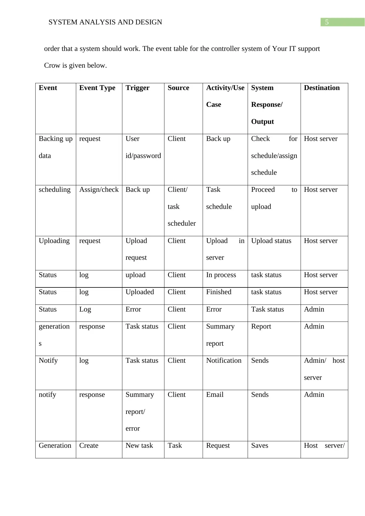
order that a system should work. The event table for the controller system of Your IT support
Crow is given below.
Event Event Type Trigger Source Activity/Use
Case
System
Response/
Output
Destination
Backing up
data
request User
id/password
Client Back up Check for
schedule/assign
schedule
Host server
scheduling Assign/check Back up Client/
task
scheduler
Task
schedule
Proceed to
upload
Host server
Uploading request Upload
request
Client Upload in
server
Upload status Host server
Status log upload Client In process task status Host server
Status log Uploaded Client Finished task status Host server
Status Log Error Client Error Task status Admin
generation
s
response Task status Client Summary
report
Report Admin
Notify log Task status Client Notification Sends Admin/ host
server
notify response Summary
report/
error
Client Email Sends Admin
Generation Create New task Task Request Saves Host server/
⊘ This is a preview!⊘
Do you want full access?
Subscribe today to unlock all pages.
Trusted by 1+ million students worldwide

6SYSTEM ANALYSIS AND DESIGN
schedule scheduler client
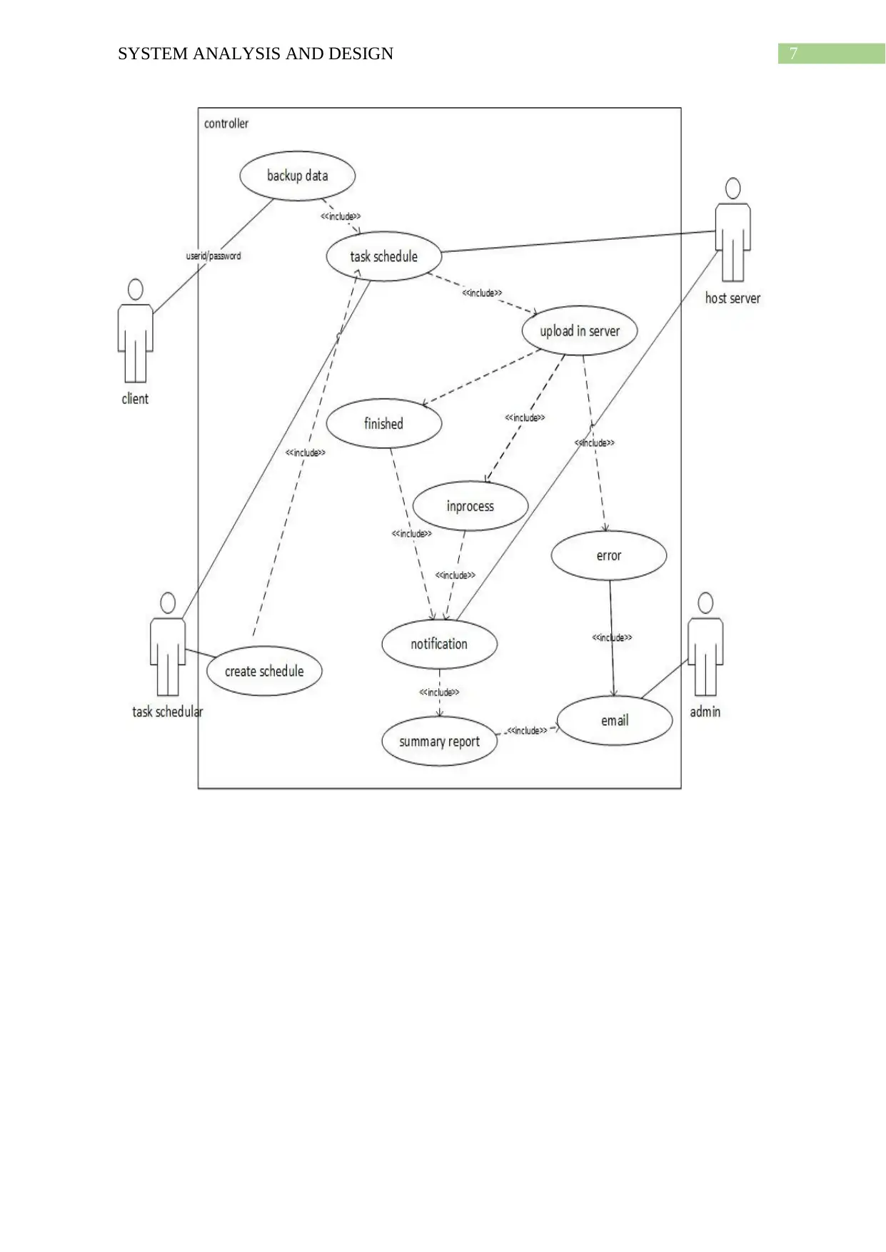
Use case Diagram
In use case modelling, the use-case diagram is the basic representation of the
interaction that takes place between the user and the system to show its relationship between
the events or use cases. It helps in identifying all the types of users and their involvement in
the system so that the developed system can interact as designed (Kim et al. 2015). The use
cases basically show the process or events, and actors show the user. The relationship can be
presented by multiple types of notations basically include, extend, generalisation, association
etc. Figure 1 shows the fully developed use case diagram of the current system with the help
of event table.
schedule scheduler client
Use case Diagram
In use case modelling, the use-case diagram is the basic representation of the
interaction that takes place between the user and the system to show its relationship between
the events or use cases. It helps in identifying all the types of users and their involvement in
the system so that the developed system can interact as designed (Kim et al. 2015). The use
cases basically show the process or events, and actors show the user. The relationship can be
presented by multiple types of notations basically include, extend, generalisation, association
etc. Figure 1 shows the fully developed use case diagram of the current system with the help
of event table.
Paraphrase This Document
Need a fresh take? Get an instant paraphrase of this document with our AI Paraphraser
7SYSTEM ANALYSIS AND DESIGN
8SYSTEM ANALYSIS AND DESIGN
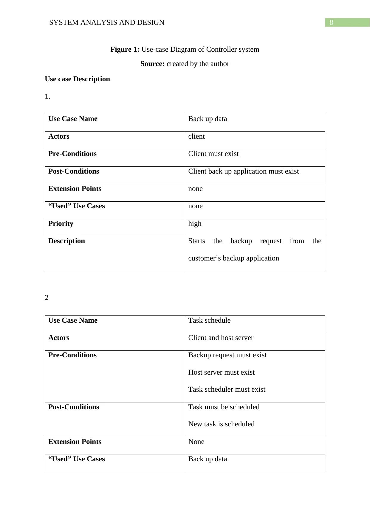
Figure 1: Use-case Diagram of Controller system
Source: created by the author
Use case Description
1.
Use Case Name Back up data
Actors client
Pre-Conditions Client must exist
Post-Conditions Client back up application must exist
Extension Points none
“Used” Use Cases none
Priority high
Description Starts the backup request from the
customer’s backup application
2
Use Case Name Task schedule
Actors Client and host server
Pre-Conditions Backup request must exist
Host server must exist
Task scheduler must exist
Post-Conditions Task must be scheduled
New task is scheduled
Extension Points None
“Used” Use Cases Back up data
⊘ This is a preview!⊘
Do you want full access?
Subscribe today to unlock all pages.
Trusted by 1+ million students worldwide

9SYSTEM ANALYSIS AND DESIGN
Priority High
Description Checks the task schedule if not then create
new schedule
3
Use Case Name Upload in server
Actors Client and host server
Pre-Conditions Task schedule must exist
Client data must exist
Host server must exist
Post-Conditions Upload should start
Extension Points None
“Used” Use Cases Task schedule
Priority High
Description Upload the client’s data
4
Use Case Name Finished
Actors Client and host server
Pre-Conditions Uploading should start
Post-Conditions Last file should uploaded
Extension Points None
“Used” Use Cases Upload in server
Priority High
Description Checks the task schedule if not then create
new schedule
3
Use Case Name Upload in server
Actors Client and host server
Pre-Conditions Task schedule must exist
Client data must exist
Host server must exist
Post-Conditions Upload should start
Extension Points None
“Used” Use Cases Task schedule
Priority High
Description Upload the client’s data
4
Use Case Name Finished
Actors Client and host server
Pre-Conditions Uploading should start
Post-Conditions Last file should uploaded
Extension Points None
“Used” Use Cases Upload in server
Paraphrase This Document
Need a fresh take? Get an instant paraphrase of this document with our AI Paraphraser
10SYSTEM ANALYSIS AND DESIGN
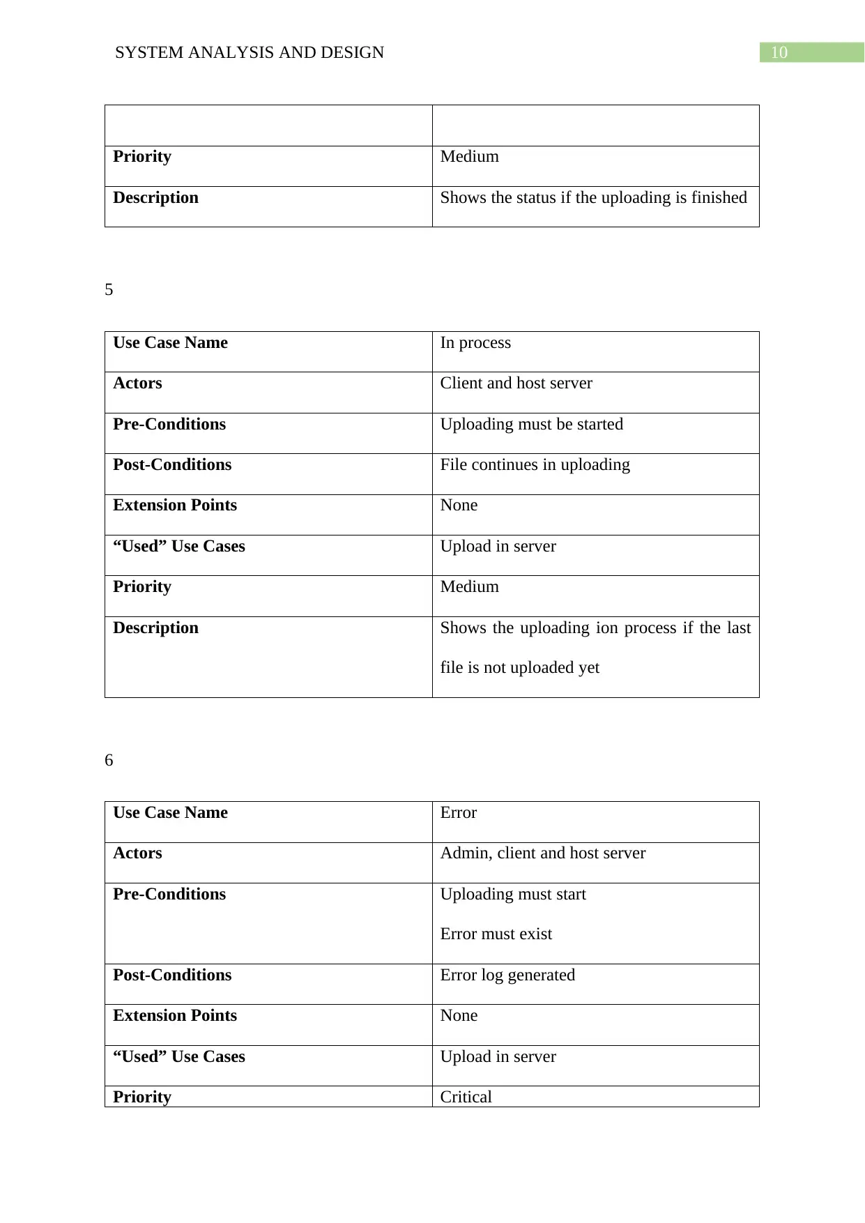
Priority Medium
Description Shows the status if the uploading is finished
5
Use Case Name In process
Actors Client and host server
Pre-Conditions Uploading must be started
Post-Conditions File continues in uploading
Extension Points None
“Used” Use Cases Upload in server
Priority Medium
Description Shows the uploading ion process if the last
file is not uploaded yet
6
Use Case Name Error
Actors Admin, client and host server
Pre-Conditions Uploading must start
Error must exist
Post-Conditions Error log generated
Extension Points None
“Used” Use Cases Upload in server
Priority Critical
Priority Medium
Description Shows the status if the uploading is finished
5
Use Case Name In process
Actors Client and host server
Pre-Conditions Uploading must be started
Post-Conditions File continues in uploading
Extension Points None
“Used” Use Cases Upload in server
Priority Medium
Description Shows the uploading ion process if the last
file is not uploaded yet
6
Use Case Name Error
Actors Admin, client and host server
Pre-Conditions Uploading must start
Error must exist
Post-Conditions Error log generated
Extension Points None
“Used” Use Cases Upload in server
Priority Critical
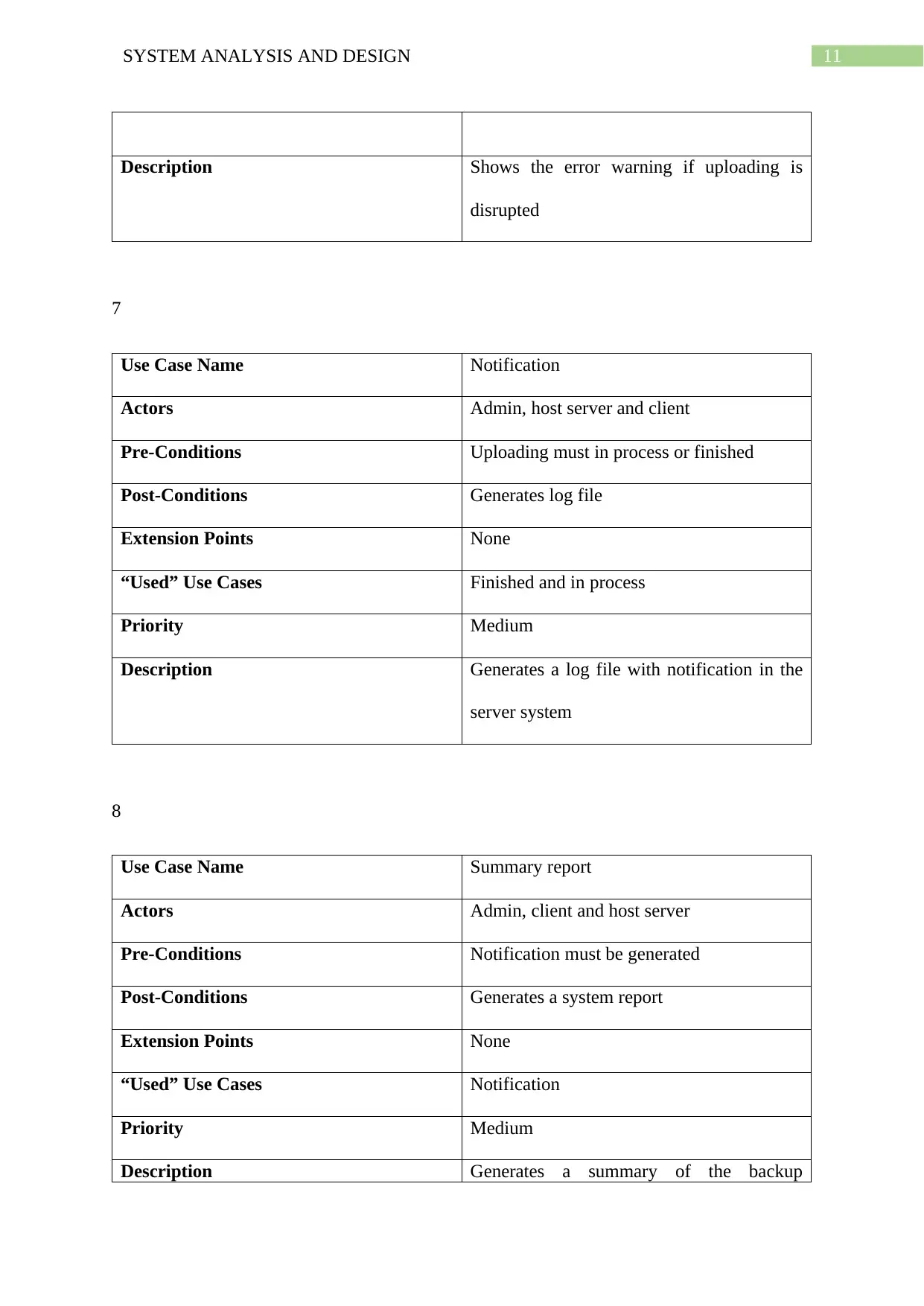
11SYSTEM ANALYSIS AND DESIGN
Description Shows the error warning if uploading is
disrupted
7
Use Case Name Notification
Actors Admin, host server and client
Pre-Conditions Uploading must in process or finished
Post-Conditions Generates log file
Extension Points None
“Used” Use Cases Finished and in process
Priority Medium
Description Generates a log file with notification in the
server system
8
Use Case Name Summary report
Actors Admin, client and host server
Pre-Conditions Notification must be generated
Post-Conditions Generates a system report
Extension Points None
“Used” Use Cases Notification
Priority Medium
Description Generates a summary of the backup
⊘ This is a preview!⊘
Do you want full access?
Subscribe today to unlock all pages.
Trusted by 1+ million students worldwide
1 out of 19
Related Documents


Your All-in-One AI-Powered Toolkit for Academic Success.
+13062052269
info@desklib.com
Available 24*7 on WhatsApp / Email
![[object Object]](/_next/static/media/star-bottom.7253800d.svg)
Unlock your academic potential
Copyright © 2020–2026 A2Z Services. All Rights Reserved. Developed and managed by ZUCOL.