CofeeMakerFactory Process Pattern Creation: UML Diagram and C++ Code

Verified

Added on  2022/08/21

|8
|991
|17
Report
AI Summary
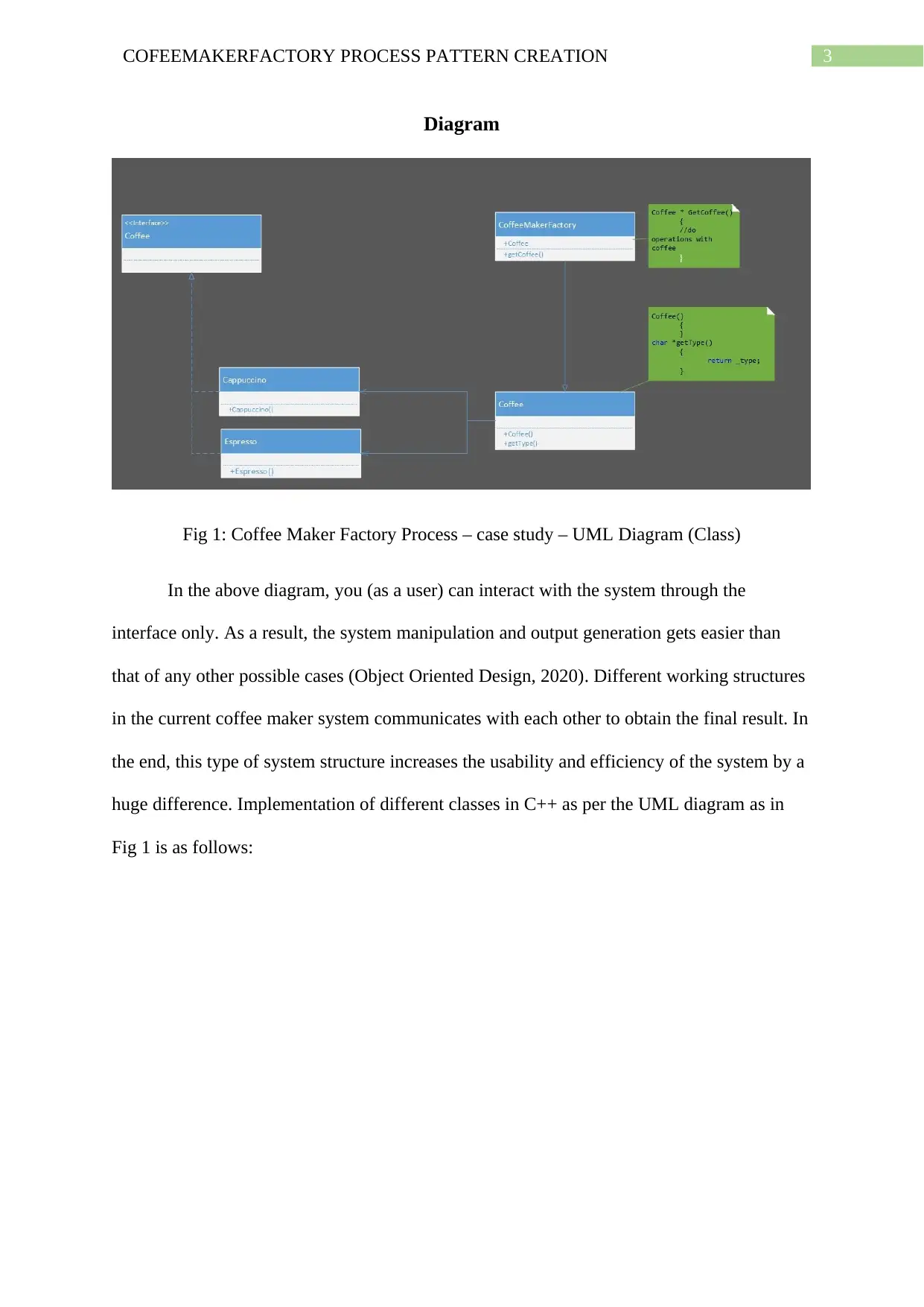
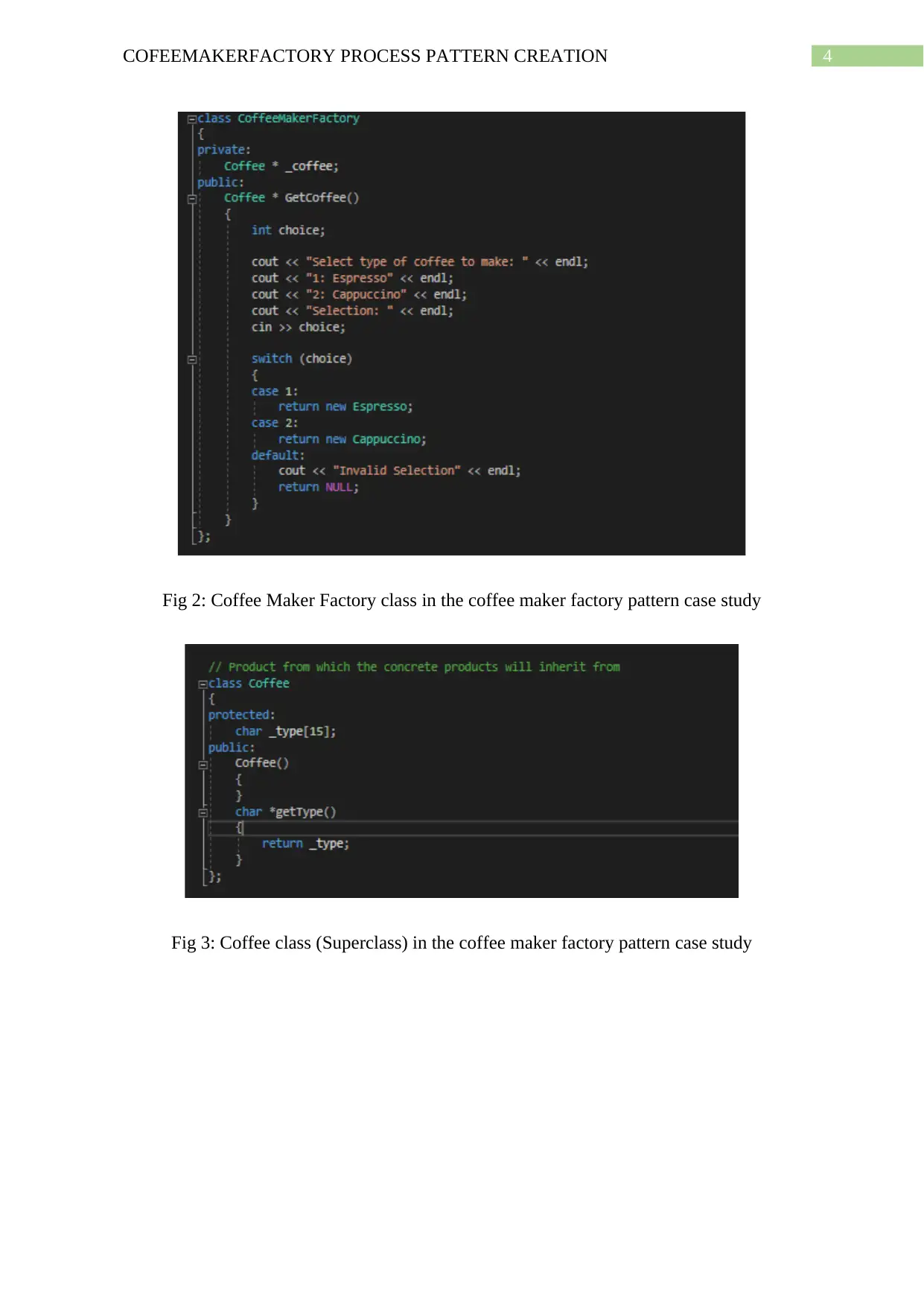
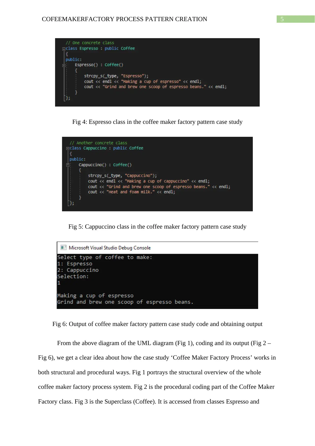
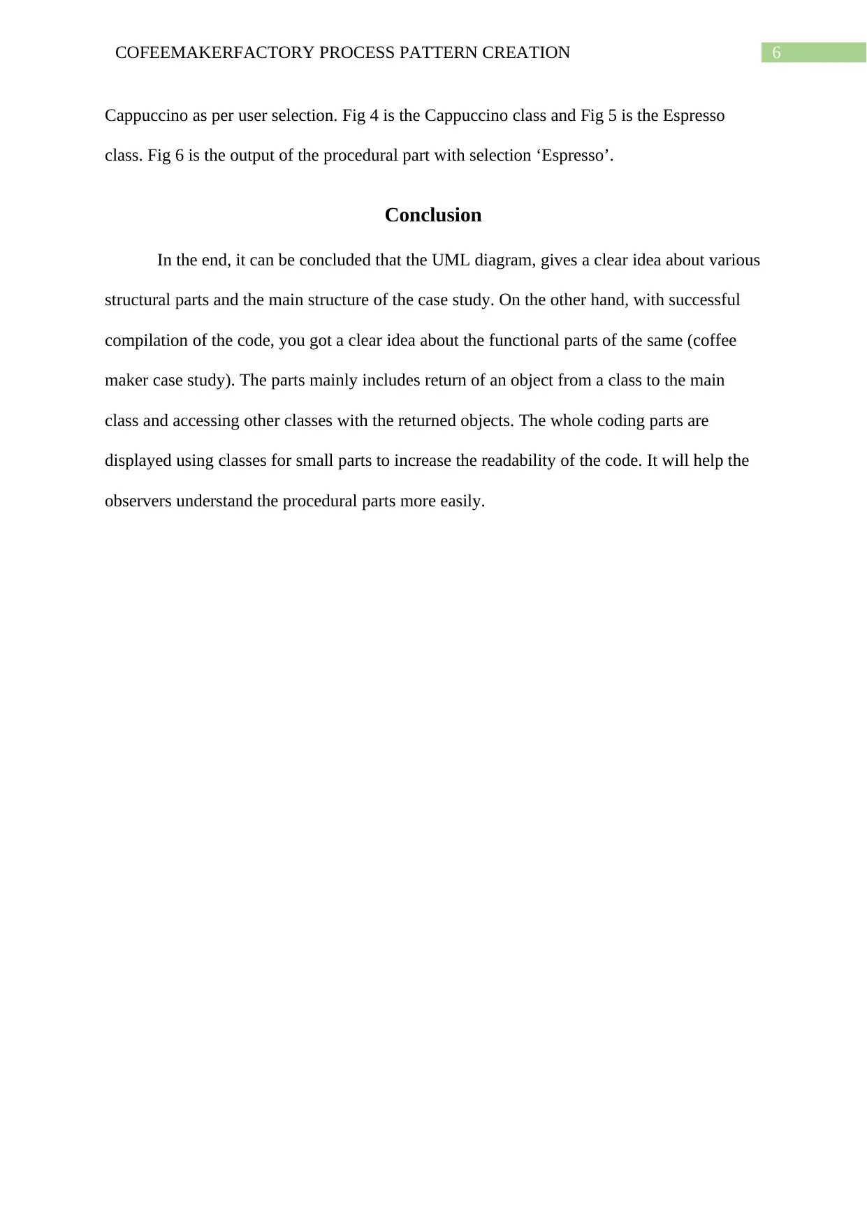
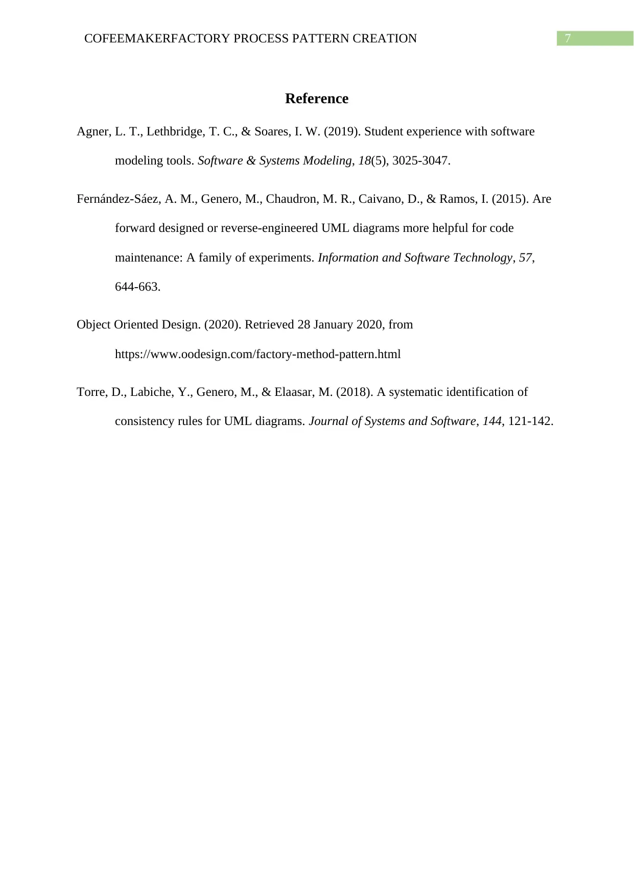
This report presents a case study of the Coffee Maker Factory process, utilizing UML diagrams to illustrate system structure and interactions. The report delves into the forward design of the use case, focusing on both structural and functional aspects. It provides a detailed explanation of the UML diagram, implemented using Microsoft Visio, and demonstrates how to translate the diagram into corresponding C++ object-oriented code. The report includes diagrams of different classes and their interactions, showcasing the implementation of the Coffee Maker Factory pattern. The report concludes by summarizing the benefits of using UML diagrams for clear structural representation and the effectiveness of the C++ code implementation in realizing the functional requirements of the coffee maker system. The provided code snippets demonstrate the creation of classes, superclasses, and outputs based on user selection, ultimately increasing the usability and efficiency of the system.
Document Page
Running head: COFEEMAKERFACTORY PROCESS PATTERN CREATION
CofeeMakerFactory Process Pattern Creation
Name of the Student
Name of the University
Author Note
tabler-icon-diamond-filled.svg

Paraphrase This Document

Need a fresh take? Get an instant paraphrase of this document with our AI Paraphraser
Document Page
1COFEEMAKERFACTORY PROCESS PATTERN CREATION
Table of Contents
Introduction................................................................................................................................2
Discussion..................................................................................................................................2
Diagram..................................................................................................................................3
Conclusion..................................................................................................................................6
Reference....................................................................................................................................7
Document Page
2COFEEMAKERFACTORY PROCESS PATTERN CREATION
Introduction
A UML diagram is used to represent a system structure along with its interactions
with various actors or classes. The diagram generated using UML can be both structural and
functional. In the following parts of this paper, a case study of the coffee maker factory
process will be used and you will get a detailed idea about the UML diagram (Torre et al.,
2018). In addition you will also get accustomed about how to implement an UML diagram
into corresponding Object Oriented Code (C++ will be discussed here).
Discussion
The UML diagram will be used to explain the Forward design of the Use case ‘Coffee
Maker Factory Process.’ The functional part of the use case will be discussed along with the
coding of the same in the C++ Object Oriented form. The coding part will solely be based on
the concept of objects (Fernández-Sáez et al., 2015). As for the use case ‘Coffee Maker
Factory’, there will be an interface system where the user will wet a prompt to select the type
of coffee that s/he wants. Upon entering the choice, s/he will receive his /her selected coffee.
The whole task will be done on an object-based return type coding using c++ programming
language.
There are many UML drawing tools that can be used to draw any required system
UML diagram. The tools varies from Lucidchart to AgroUML, Magic Draw, Microsoft Visio,
and many more (Agner, Lethbridge & Soares, 2019). For the ease of drawing and
understanding the UML diagram, Microsoft Visio is used to draw the following UML
diagram in Fig 1. It is a popular chart making and visualization software and is used to
reverse engineer various coding languages to some extent. The language can vary from,
VSDM to C++, VSDX, and C#. The following diagram can be obtained from the ‘Coffee
Maker Factory Process’ case study.
Document Page
3COFEEMAKERFACTORY PROCESS PATTERN CREATION
Diagram
Fig 1: Coffee Maker Factory Process – case study – UML Diagram (Class)
In the above diagram, you (as a user) can interact with the system through the
interface only. As a result, the system manipulation and output generation gets easier than
that of any other possible cases (Object Oriented Design, 2020). Different working structures
in the current coffee maker system communicates with each other to obtain the final result. In
the end, this type of system structure increases the usability and efficiency of the system by a
huge difference. Implementation of different classes in C++ as per the UML diagram as in
Fig 1 is as follows:
tabler-icon-diamond-filled.svg

Paraphrase This Document

Need a fresh take? Get an instant paraphrase of this document with our AI Paraphraser
Document Page
4COFEEMAKERFACTORY PROCESS PATTERN CREATION
Fig 2: Coffee Maker Factory class in the coffee maker factory pattern case study
Fig 3: Coffee class (Superclass) in the coffee maker factory pattern case study
Document Page
5COFEEMAKERFACTORY PROCESS PATTERN CREATION
Fig 4: Espresso class in the coffee maker factory pattern case study
Fig 5: Cappuccino class in the coffee maker factory pattern case study
Fig 6: Output of coffee maker factory pattern case study code and obtaining output
From the above diagram of the UML diagram (Fig 1), coding and its output (Fig 2 –
Fig 6), we get a clear idea about how the case study ‘Coffee Maker Factory Process’ works in
both structural and procedural ways. Fig 1 portrays the structural overview of the whole
coffee maker factory process system. Fig 2 is the procedural coding part of the Coffee Maker
Factory class. Fig 3 is the Superclass (Coffee). It is accessed from classes Espresso and
Document Page
6COFEEMAKERFACTORY PROCESS PATTERN CREATION
Cappuccino as per user selection. Fig 4 is the Cappuccino class and Fig 5 is the Espresso
class. Fig 6 is the output of the procedural part with selection ‘Espresso’.
Conclusion
In the end, it can be concluded that the UML diagram, gives a clear idea about various
structural parts and the main structure of the case study. On the other hand, with successful
compilation of the code, you got a clear idea about the functional parts of the same (coffee
maker case study). The parts mainly includes return of an object from a class to the main
class and accessing other classes with the returned objects. The whole coding parts are
displayed using classes for small parts to increase the readability of the code. It will help the
observers understand the procedural parts more easily.
tabler-icon-diamond-filled.svg

Paraphrase This Document

Need a fresh take? Get an instant paraphrase of this document with our AI Paraphraser
Document Page
7COFEEMAKERFACTORY PROCESS PATTERN CREATION
Reference
Agner, L. T., Lethbridge, T. C., & Soares, I. W. (2019). Student experience with software
modeling tools. Software & Systems Modeling, 18(5), 3025-3047.
Fernández-Sáez, A. M., Genero, M., Chaudron, M. R., Caivano, D., & Ramos, I. (2015). Are
forward designed or reverse-engineered UML diagrams more helpful for code
maintenance: A family of experiments. Information and Software Technology, 57,
644-663.
Object Oriented Design. (2020). Retrieved 28 January 2020, from
https://www.oodesign.com/factory-method-pattern.html
Torre, D., Labiche, Y., Genero, M., & Elaasar, M. (2018). A systematic identification of
consistency rules for UML diagrams. Journal of Systems and Software, 144, 121-142.
chevron_up_icon
1 out of 8
circle_padding
hide_on_mobile
zoom_out_icon
[object Object]