Final Report: Performance Analysis of a 4-Stroke Combustion Engine
VerifiedAdded on 2022/12/02
|26
|10560
|268
Report
AI Summary
This report presents a comprehensive performance analysis of a 4-stroke combustion engine. It begins with an introduction to internal combustion engines, their significance in energy development, and the technical background of 4-stroke engines, including intake, compression, power, and exhaust strokes. The report then delves into the performance analysis, comparing air-fuel ratios and detailing the experimental setup used. The results and discussion section analyzes the engine's performance based on the experimental data, followed by a conclusion summarizing the key findings and suggestions for future work. The report also includes a literature review covering various aspects of internal combustion engines, including fuel injection parameters and the historical development of these engines, and the report also includes figures and tables to support the findings. The study aims to characterize and parameterize the output of internal combustion engines to understand the factors influencing their functionality.

Performance analysis of a combustion engine (4 stroke)
Paraphrase This Document
Need a fresh take? Get an instant paraphrase of this document with our AI Paraphraser
Contents
Abstract.......................................................................................................................................................3
Acknowledgements.....................................................................................................................................3
1.0 Introduction...........................................................................................................................................3
1.1 Technical background........................................................................................................................4
1.1 Literature review..........................................................................................................................4
1.2 Aims and objectives.....................................................................................................................8
2.0 performance analysis.............................................................................................................................8
2. 1 Comparison of air fuel ratio............................................................................................................12
2.2 Experiment setup.............................................................................................................................16
3. results and discussion............................................................................................................................19
4.0 conclusion............................................................................................................................................20
4.1 Future work.....................................................................................................................................21
References.............................................................................................................................................23
Figure 1 inside a 4 stroke Engine - image credits to (Dumitrache, 2019)....................................................7
Figure 2 bottom view of the Engine block. The cylinders, oil spray nozzle and half of the main bearings
can easily be identified................................................................................................................................8
Figure 3 a graph of speed verses load showing pressure iterations of an Engine.......................................10
Figure 4 comparing torque performances..................................................................................................11
Figure 5 a graph showing the effiect of compresion ratio in an Engine.....................................................12
Figure 6 a diagram showing the power engine variance at different compression ratios...........................12
Table 1fuel charachterictics.......................................................................................................................19
Table 2 experiment model.........................................................................................................................19
Abstract
The popularity of internal combustion engines such as petrol and diesel engines stem from the
combined elevated take level and low energy consumption of their appealing conducting
capacity. The crucial function of these features has resulted to the growth of charger technology,
which has resulted in significant power density and a significant rise in efficient stress.
Consequently, the purpose is to characterize and parameterize the output of internal combustion
enginery in order to study the reasons and impacts that determine the functionality of the IC
engine.
Acknowledgements
1.0 Introduction
The internal combustion engine (ICE) is a thermal motor in which a petrol combustion takes
place in the combustion chamber with an oxidizer (typically air) that is component and parcel of
the operating stream loop. The extension of high temperature and high-pressure gases generated
by combustion in an internal combustion engine adds immediate power to a certain engine
element. Typically, the force is introduced to pistons, blades, rotors or a piston. This force
transforms the element into helpful mechanical energy through the range.
Energy is the fundamental requirement for any country's economic development. A number of
indispensable tasks are to be stopped when the energy supply ends. As a result, the real extent of
the role played by electricity in the construction of the advanced countries can be virtually
difficult to evaluate, resulting in longer operating hours, increased agriculture and industrial
manufacturing, healthier and more balanced lives.
Indeed, the energy used per individual is closely related to his living standards. The higher a
country's precipitate energy consumption, the higher its people live standards. The elevated
demographic growth level and rapidly evolving way of life have changed significantly and
gradually in the industry and transport industry. As a result, the consumption of oil derivatives
has risen to a high degree, which is much greater than appreciated.
The piston's highest dead centre (TDC) is the place closest to the pumps; the lowest dead zone
(BDC) is on the reverse end. The motion, in conjunction with the related method, of a piston
from a TDC to a BDC is a stroke. The crank shaft rotates at an almost steady velocity while an
engine is in service. Each piston gets two kicks, in the following order, in a 4-stroke ICE.
1.1 Technical background
An internal combustion engine is a four-stroke cycle motor which uses four separate piston strokes for a
single working cycle (take-in, compression, energy and exhaust). The piston completes a single operating
cycle in two full cylinder passes. Two revolutions (720 °) of the crankshaft are required for an operational
cycle. The four-cycle engine is the smaller engine's most prevalent form. In addition to input,
⊘ This is a preview!⊘
Do you want full access?
Subscribe today to unlock all pages.
Trusted by 1+ million students worldwide
compression, ignition, energy and exhaust strokes, the four-stroke cycle motor completes five strokes in a
single working cycle.
The intake incident occurs when the combustion chamber is filled with an air-fuel blend. When the piston
passes from TDC to BDC, the intake activity takes place, and the intake valve is open. The piston motion
to BDC causes a small cylinder pressure. Atmospheric stress forces the air / fuel combination to fill the
low-pressure region generated by piston motion through the open intake valve into the engine. As the air-
fuel-mix continues to run through its own inertia while the piston started to alter direction, the cylinders
still fill slightly past BDC. The intake valve is still open a few degrees after BDC. The layout depends on
the motor.
A few degrees of crankshaft rotation after BDC remain open for the intake Valve. Depending on the
layout of the motor. The valve of intake is then shut and the combination of air and fuel inside the
cylinder is closed.
A compression stroke happens when the air-fuel blend is pulled into the cylinder. The room is screened
for load forming. The charge is the quantity of the blend of air and fuel that is trapped inside the
incinerator chamber. The compression of the air-to-fuel mixture allows more energy to be released when
charges are fired. For compression sealing of cylinders, the intake and exhaust valves must be closed.
Compression is the method by which the charge is reduced or reduced in the combustion chamber from a
big volume to a lower volume. The flywheel keeps the momentum needed to reduce the load.
The present prominence of inward ignition motors, for example, gas and diesel motors, begins
from the mix of their appealing driving exhibition because of high toque levels and low fuel
utilization. The unequivocal job of these attributes has prompted the advancement of charger
innovation, bringing about a surprising increment in power thickness and mean viable weight.
Turbo charging innovation has been broadly utilized in motors for various applications, going
from little vehicles to enormous marine vessels, on account of its specialized points of interest,
for example, no interest for driving force from the motor and magnificent charging impacts
during sac task at mid to high motor rates. Be that as it may, there is a reaction time delay,
particularly for traveller vehicle turbochargers, which can be tricky since witticism driving is
done under downtown conditions at mid to low motor velocities bringing about a "turbo slack"
when there is abrupt acceleration[6].In late years, the engine vehicle industry goes for the little
estimated and high power thickness motor, while cutting back (little size and weight sparing) and
estimating the improvement in fuel utilization, and canalization.
When the engine piston compresses the load, increased compressive force from the job of the
piston generates heat. The compression and heating of air-fuel vapor in the load increases the
load temperature and the vaporisation of the oil. The load temperature increases consistently in
Paraphrase This Document
Need a fresh take? Get an instant paraphrase of this document with our AI Paraphraser
the entire combustion chamber to result in quicker (fuel oxidation) combustion after ignition.
The rise in fuel vaporization happens when tiny fuel droplets are more fully vaporized from heat.
The more atoms are placed in loading vapours, the more vitality the ignition process gained.
During the burning procedure, the vitality expected to pack the charge is not exactly the power
supplied. For example, the vitality required to pack up the cargo in a normal small motor is only
one-fourth the vitality measure generated during ignition.
The pressure ratio of an engine is a check of burning chamber quantity with the cylinder at BDC
to the inflammatory chamber quantity of the cylinder at TDC. The pressure ratio is determined in
this land, together with the burning chamber design and style. Gas engines usually have a
pressure ratio of 6:1 to 10:1. The greater the pressure, the greener the engine. In order to improve
the pressure ratio, burning weight or energy in the cylinders is usually important. Whatever the
case, greater pressure levels increase the manager's work to switch over the engine. Some small
engines include a weight-enhancing frame during the pressure stroke to reduce the manager's
effort needed to turn over the engine. When charging is removed and rapidly oxidized by
synthesis the beginning (burning) occurring occasion. response to discharge heat vitality.
Ignition is the fast, oxidizing concoction response in which a fuel artificially joins with oxygen in
the environment and discharges vitality as warmth.
Legitimate ignition encompasses a brief yet restricted time for a fire throughout the combustion
chamber. The flash starts to ignite with a crankshaft turn before TDC (BTDC) at around 20 °. A
progressing front of fire consumes the barometric oxygen and oil vapour. A burning front is the
boundary separator that isolates the charge from the outcomes of burning. The front of the fire
passes through the ignition chamber until the entire charge is consumed.
The power supply is an engine job Stroke where the cylinders are powered by warm gases far
away from the chamber head. The cylindrical force and subsequent motion are shifted to the
crankshaft through the associated bar to apply the torque. The linked torque begins to turn
crankshaft. The measurement of the supplied torque is governed by the weight of the cylinder,
the cylinder size and the engine toss. The two valves are closed during the power strike.
The stroke occurs when particulates are thrown away and discharged into the environment from
the ignition chamber. The stroke of fumes is the final stroke and occurs when the fume valve is
opened and the input valve is shut off. The growth of cylinder clears the atmosphere from fumes.
The cylinders arrive at BDC and the chamber is charged with smoke gas when the energy Stroke
ignition is completed. The smoke valve will be opened, and the flywheel and other moving parts
will push the cylinder back to TDC, limiting the gaseous fumes through the open fumes valve.
The cylinder is at TDC, and a working cycle is completed towards the completion of the stroke.
1.1 Literature review
For a diesel motor, fuel infusion weight (FIP) and infusion timings are significant parameters,
which impact the motor execution, discharges, and burning. Other infusion parameters
influencing motor execution are rate of infusion, infusion design, number of infusions and so on.
A solitary chamber inquire about motor was utilized to tentatively decide the impacts of fuel
infusion methodologies and infusion timings on motor burning, execution and outflow attributes.
The tests were led at steady speed (2500 rpm) with two FIPs (500 and 1000 bars individually)
and diverse beginning of infusion (SOI) timings. Chamber weight and rate of warmth discharge
(ROHR) were observed to be higher for lower FIPs anyway propelled infusion timings gave
higher ROHR in early ignition stages. Brake warm productivity (BTE) expanded with expanded
infusion weights while fumes gas temperature and brake mean successful weight (BMEP)
expanded up to 500 bars. These parameters decreased somewhat with increment in FIP.
Different researchers and specialists added to the advancement of inside burning motors. In
1791, John Barber built up the gas turbine. In 1794 Thomas Mead protected a gas motor.
Additionally, in 1794, Robert Street protected an inside burning motor, which was likewise the
first to utilize fluid fuel, and manufactured a motor around that time. In 1798, John Stevens
assembled the main American inside ignition motor. In 1807, French architects Nicephorus
Niepce (who proceeded to imagine photography) and Claude Niepce ran a model inner ignition
motor, utilizing controlled residue blasts, the Pyréolophore. This motor fuelled a pontoon on the
Saône waterway, France. That year, the Swiss designer François Isaac de Rivaz assembled an
inside burning motor touched off by an electric sparkle. In 1823, Samuel Brown protected the
primary interior burning motor to be connected mechanically.
In 1854 in the UK, the Italian innovators Eugenio Barsanti and Felice Matteucci acquired an
affirmation "Getting thought process control by the blast of gases". In 1857 the Great Seal Patent
Office surrendered them patent No.1655 for the innovation of an Improved Apparatus for
Obtaining Motive Power from Gases. In 1860, Belgium's Jean Joseph Etienne Lenoir supplied a
⊘ This is a preview!⊘
Do you want full access?
Subscribe today to unlock all pages.
Trusted by 1+ million students worldwide
gas-finished inner combustion engine, Barzani and Patitucci obtained distinct permits for the
same development in France, Belgium, Piedmont and some part of the spectrum of 1857 and
1857[7]. The main climate gas engine was shielded by Nikolaus Otto in 1864. The main
commercial fluid fuelled into the ignition engine was intended by American George Brayton in
1872. The four-cycle engine compact charge was authorized by Nikolaus Otto in 1876,
collaborating with Gottlieb Daimler and Wilhelm Maybach. Karl Benz shielded a two-time
reliable petrol engine in 1879. Afterward, in 1886, Karl Benz started the main business creation
of engine vehicles with the inside ignition motor. In 1892, Rudolf Diesel built up the main
compacted charge, pressure start motor. In 1926, Robert Goddard propelled the primary fluid
powered rocket. In 1939, the Heinkel He 178 turned into the world's first fly air ship.
The engine cube, usually produced of strong metal or aluminum, is the basis for an internal
ignition engine. There are rooms in the engine park. Motors with a room organized in more than
one room are usually either in 1 thrust (directly) or in 2 rows (rocket engine or V engine); three
rows are incidentally used (W engine) in the modern engines and other engine models can be
designed and used. For bikes and small hardware motors single chamber motors are normal.
Water cooled engines comprise parts where drying fluids (air cover) squares are placed in the
engine plaza. In contrast to having a water coat, the square has blades which project far removed
from it to cool by legitimately move warmth into the air. Some of them are air cooled. The
chamber dividers are generally wrapped up by sharpening to get a cross bring forth, which is
better ready to hold the oil. A too unpleasant surface would rapidly hurt the motor by over the
top wear on the cylinder.
The cylinders are short tube-shaped parts which seal one finish of the chamber from the high
weight of the compacted air and burning items and slide persistently inside it while the motor is
in task the cylinder's top mass is called its curve and is usually straight or level. Some double-
stroke engines use redirector head cylinders. With the exception of a fundamental fortification
framework (the brick net), cylinders are accessible at the foundation and void. When the engine
operates, the cooking tank gas weight adds energy to the cylindrical cap that is transferred to a
dudgeon stick through the internet. Each cylinder is ringed around its periphery so that gas does
not pour into the box or the oil into the combustion system for the most portion. A ventilation
framework controls the tiny quantity of gas that passes the cylinder in ordinary activities. The
crankcase is part of the air-fuel manner with two-stroke gas engines and due to its continuous
advancement it does not have to deal with an alternate crankcase ventilation structure.
Paraphrase This Document
Need a fresh take? Get an instant paraphrase of this document with our AI Paraphraser
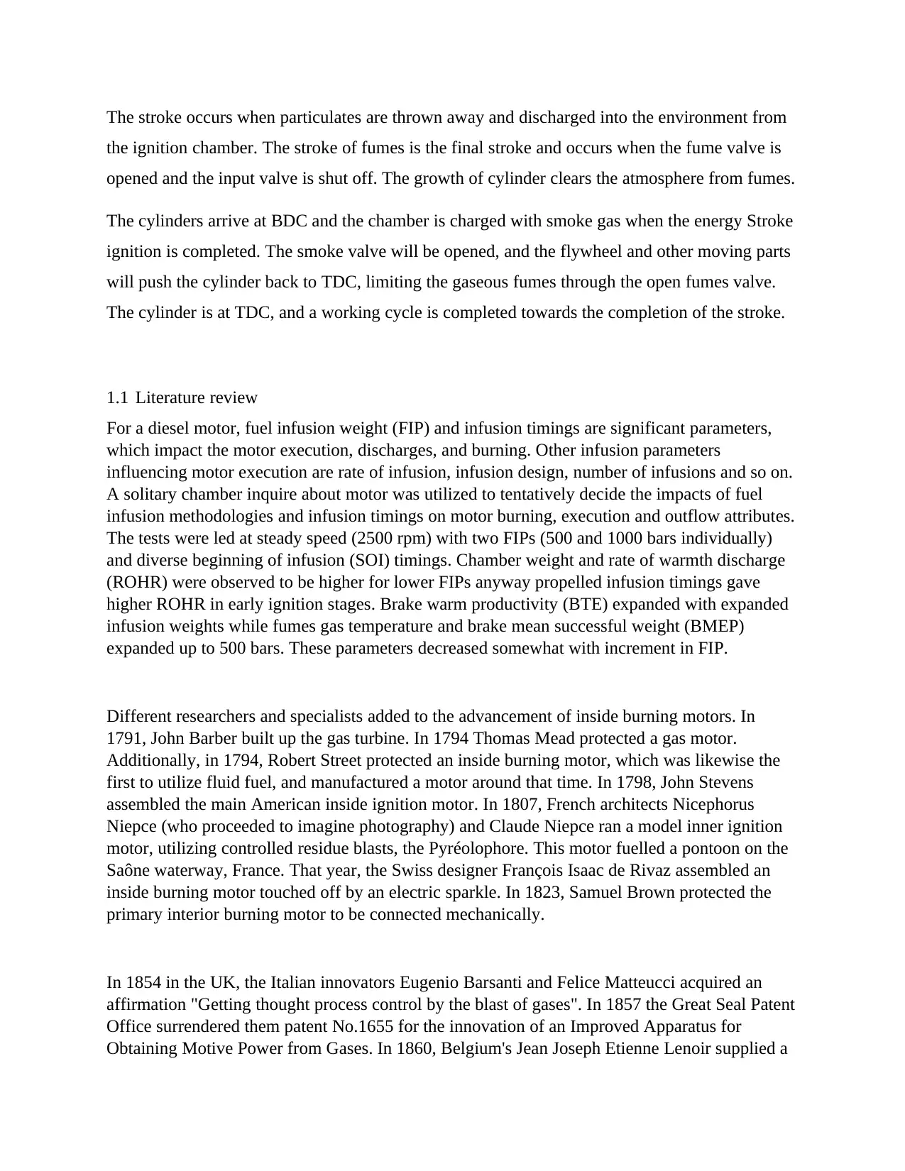
Figure 1 inside a 4 stroke Engine - image credits to (Dumitrache, 2019)
The chamber head is appended to the motor square by various jolts or studs. It has a few
capacities. It includes brief pipes (pipes) for input and outlet and the corresponding intake valves
that allow the cell a possibility to be charged up with real water and fumes which are accessible
to allow ignition gas to flow back. The tank top locks these cylinders as a reverse. However, 2-
hit cabinet-searched engines directly connect gas outlets with the tank divider without a valve;
the cylinders check their entrance and impediment. The camera cabinet also contains the
sparkling beginning engine example and the injector for engines using immediate infusion. SI
motors can utilize a carburettor or fuel infusion as port infusion or direct infusion. For all
chambers, the majority of SI engines have a single flash, with the exception of some have two.
The gas does not flow from the tank top to the engine surface with a head gasket. A single or a
few camships and springs–or in certain motors–are restricted to the opening and closing of the
cylinders. The pipes do not require any locks. The camshaft can click the valve stem straight or
can track a rocker arm again legally or with a pushrod.
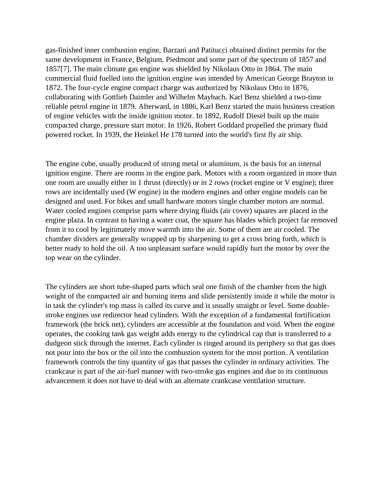
Figure 2 bottom view of the Engine block. The cylinders, oil spray nozzle and half of the main bearings can easily be identified.
The crankcase is attached to the foundation by means of a swamp, which collects the dropping
oil again during regular cycle tasks. The space between the room square and the swamp is fitted
The chamber head is appended to the motor square by various jolts or studs. It has a few
capacities. It includes brief pipes (pipes) for input and outlet and the corresponding intake valves
that allow the cell a possibility to be charged up with real water and fumes which are accessible
to allow ignition gas to flow back. The tank top locks these cylinders as a reverse. However, 2-
hit cabinet-searched engines directly connect gas outlets with the tank divider without a valve;
the cylinders check their entrance and impediment. The camera cabinet also contains the
sparkling beginning engine example and the injector for engines using immediate infusion. SI
motors can utilize a carburettor or fuel infusion as port infusion or direct infusion. For all
chambers, the majority of SI engines have a single flash, with the exception of some have two.
The gas does not flow from the tank top to the engine surface with a head gasket. A single or a
few camships and springs–or in certain motors–are restricted to the opening and closing of the
cylinders. The pipes do not require any locks. The camshaft can click the valve stem straight or
can track a rocker arm again legally or with a pushrod.
Figure 2 bottom view of the Engine block. The cylinders, oil spray nozzle and half of the main bearings can easily be identified.
The crankcase is attached to the foundation by means of a swamp, which collects the dropping
oil again during regular cycle tasks. The space between the room square and the swamp is fitted
with a cylindrical shaft that shifts in response to linear motion of the cylinders. The crankshaft is
kept by a basic angle with regard to the engine circle, which allows it to rotate. Bulkheads are
part of every principal frame unit in the crankcase; the other quarter is a separable base.
Sometimes, instead of just a few smaller caps, a lone principal carrying rack is used. The
assembly platform is connected with crankshaft equilibrium (cranks) at one side and the
cylinders at the reverse side by the gudgeon button and so shifts the energy and decipheres the
reaction of the cylinder to the round shaft motion. A small start is called the finishing of the
interface bar attached to the gudgeon and a enormous start is called on the other side where the
crankshaft is linked. The huge top has a separable quarter to allow the crankshaft to get together.
It is kept by removable jolts together at the associated point.
The present fame of interior burning motors, for example, gas and diesel motors, starts from the
high toque levels and low fuel utilization. The unequivocal job of these attributes has prompted
the advancement of charger innovation, bringing about a striking increment in control thickness
and mean successful weight. Turbo charging innovation has been broadly utilized in motors for
various applications, running from little vehicles to huge marine vessels, on account of its
specialized points of interest, for example, no interest for driving force from the motor and
incredible charging impacts during sac task at mid to high motor speeds. In any case, there is a
reaction time delay, particularly for traveller vehicle turbochargers, which can be dangerous
since witticism driving is done under downtown conditions at mid to low motor velocities
bringing about a "turbolag" when there is unexpected acceleration. As of late, the engine vehicle
industry goes for the little estimated and high-power thickness motor, while scaling back (little
size and weight sparing) and estimating the improvement in fuel utilization, and cleanization.
The interest of practical minivehicle increments in ongoing years from such a foundation by low
fuel utilization, and when it will particularly surpass percent of the vehicle complete number of
ownerships in Japan of 2005, will grow up. Notwithstanding, intensity of a minivehicle is
deficient and there is sign of the client that speeding up power is feeble and inadmissible,
particularly at the season of a begin dash, gradeability, and passing, and so forth. For the reason,
Auto creators taking out with the high-yield.
A supercharger is a belt or apparatus driven vacuum apparatus used to increment the air
thickness at the gulf of a motor to create more power. A supercharger is associated legitimately
to the crankshaft by a belt and thusly can give a quick lift and drive on demand. As contrasted
and the turbocharger motor, a supercharger is precisely determined by the motor crankshaft.
Since the motor speed and supercharger speed are in a fixed proportion to one another, support
weight change with motor speed substantially more quickly than on account of a turbocharged
motor.
⊘ This is a preview!⊘
Do you want full access?
Subscribe today to unlock all pages.
Trusted by 1+ million students worldwide
1.2 Aims and objectives
The aims of this paper are as listed below
By characterizing the performance of Internal combustion Engine, we will be able to investigate
and parametrize the working and conditions that will influence IC engines. This will also be done
while studying the causes and effects that determine the effects of IC engine. Growing issues
about electricity and CO2 pollution are driving the search for a potential fuel for sustainable
energy. Although biomethyl has been marketed with fossil diesel for diesel engines for more
than a century, there is still a major barrier here: the absence of an awareness of combustion
conduct and emissions using biodiesels from various feedstocks.
In this study paper, the impact of oil characteristics on motor capacity and pollution with a
contemporary 3.0L V6 Jaguar gasoline motor has been investigated using a variety of biodiesel
blends. The first and second batch of biodiesel are included in the experiment.
the specific objectives for this paper include
a. determine the effect of air fuel ratio on engine performance
b. use data from previously reviewed journals to analyse engine performance
c. suggest future improvements in engine performance
2.0 performance analysis
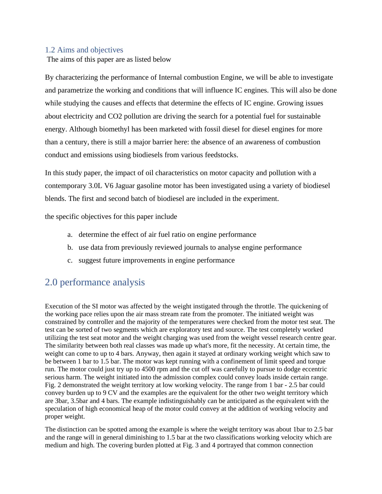
Execution of the SI motor was affected by the weight instigated through the throttle. The quickening of
the working pace relies upon the air mass stream rate from the promoter. The initiated weight was
constrained by controller and the majority of the temperatures were checked from the motor test seat. The
test can be sorted of two segments which are exploratory test and source. The test completely worked
utilizing the test seat motor and the weight charging was used from the weight vessel research centre gear.
The similarity between both real classes was made up what's more, fit the necessity. At certain time, the
weight can come to up to 4 bars. Anyway, then again it stayed at ordinary working weight which saw to
be between 1 bar to 1.5 bar. The motor was kept running with a confinement of limit speed and torque
run. The motor could just try up to 4500 rpm and the cut off was carefully to pursue to dodge eccentric
serious harm. The weight initiated into the admission complex could convey loads inside certain range.
Fig. 2 demonstrated the weight territory at low working velocity. The range from 1 bar - 2.5 bar could
convey burden up to 9 CV and the examples are the equivalent for the other two weight territory which
are 3bar, 3.5bar and 4 bars. The example indistinguishably can be anticipated as the equivalent with the
speculation of high economical heap of the motor could convey at the addition of working velocity and
proper weight.
The distinction can be spotted among the example is where the weight territory was about 1bar to 2.5 bar
and the range will in general diminishing to 1.5 bar at the two classifications working velocity which are
medium and high. The covering burden plotted at Fig. 3 and 4 portrayed that common connection
The aims of this paper are as listed below
By characterizing the performance of Internal combustion Engine, we will be able to investigate
and parametrize the working and conditions that will influence IC engines. This will also be done
while studying the causes and effects that determine the effects of IC engine. Growing issues
about electricity and CO2 pollution are driving the search for a potential fuel for sustainable
energy. Although biomethyl has been marketed with fossil diesel for diesel engines for more
than a century, there is still a major barrier here: the absence of an awareness of combustion
conduct and emissions using biodiesels from various feedstocks.
In this study paper, the impact of oil characteristics on motor capacity and pollution with a
contemporary 3.0L V6 Jaguar gasoline motor has been investigated using a variety of biodiesel
blends. The first and second batch of biodiesel are included in the experiment.
the specific objectives for this paper include
a. determine the effect of air fuel ratio on engine performance
b. use data from previously reviewed journals to analyse engine performance
c. suggest future improvements in engine performance
2.0 performance analysis
Execution of the SI motor was affected by the weight instigated through the throttle. The quickening of
the working pace relies upon the air mass stream rate from the promoter. The initiated weight was
constrained by controller and the majority of the temperatures were checked from the motor test seat. The
test can be sorted of two segments which are exploratory test and source. The test completely worked
utilizing the test seat motor and the weight charging was used from the weight vessel research centre gear.
The similarity between both real classes was made up what's more, fit the necessity. At certain time, the
weight can come to up to 4 bars. Anyway, then again it stayed at ordinary working weight which saw to
be between 1 bar to 1.5 bar. The motor was kept running with a confinement of limit speed and torque
run. The motor could just try up to 4500 rpm and the cut off was carefully to pursue to dodge eccentric
serious harm. The weight initiated into the admission complex could convey loads inside certain range.
Fig. 2 demonstrated the weight territory at low working velocity. The range from 1 bar - 2.5 bar could
convey burden up to 9 CV and the examples are the equivalent for the other two weight territory which
are 3bar, 3.5bar and 4 bars. The example indistinguishably can be anticipated as the equivalent with the
speculation of high economical heap of the motor could convey at the addition of working velocity and
proper weight.
The distinction can be spotted among the example is where the weight territory was about 1bar to 2.5 bar
and the range will in general diminishing to 1.5 bar at the two classifications working velocity which are
medium and high. The covering burden plotted at Fig. 3 and 4 portrayed that common connection
Paraphrase This Document
Need a fresh take? Get an instant paraphrase of this document with our AI Paraphraser
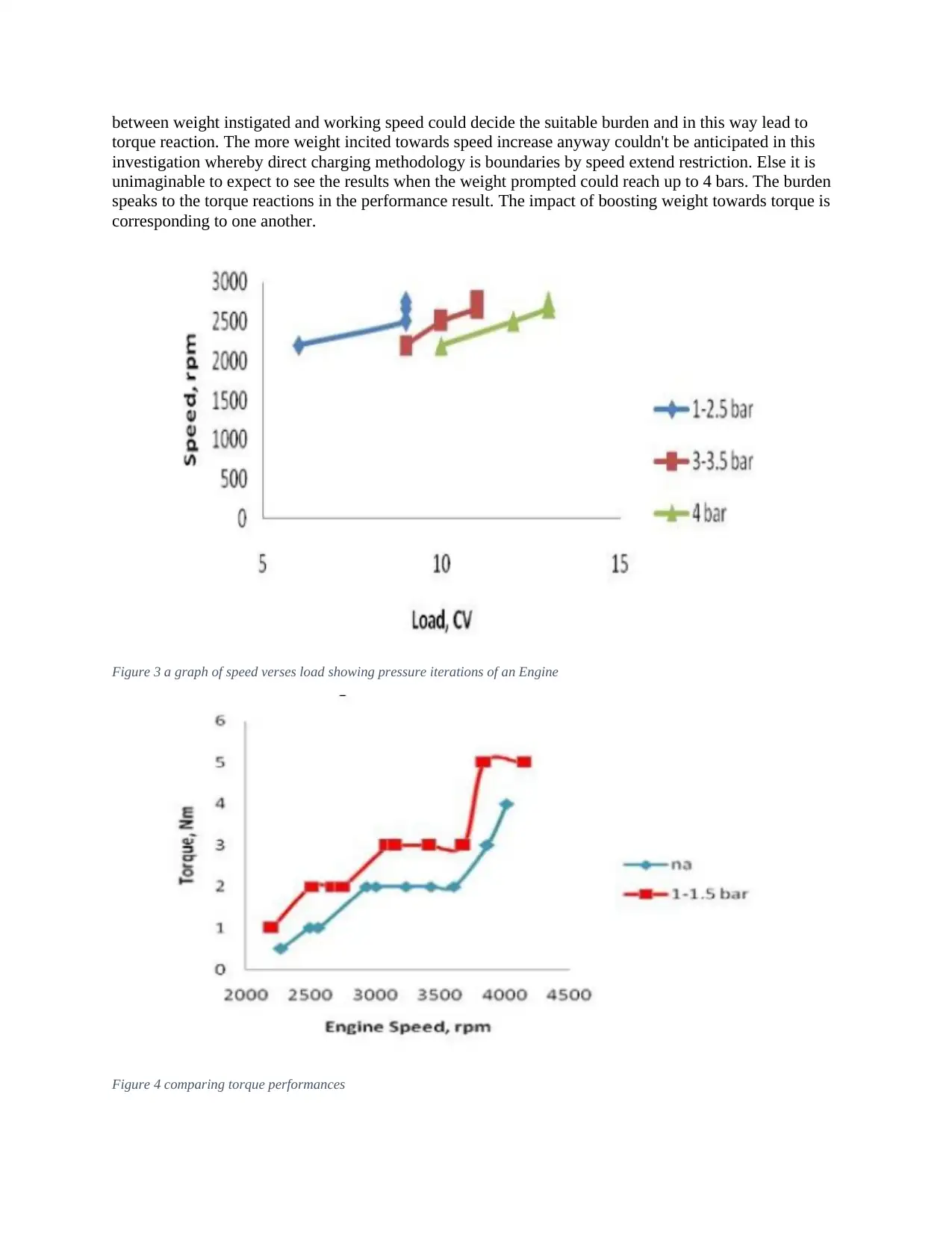
between weight instigated and working speed could decide the suitable burden and in this way lead to
torque reaction. The more weight incited towards speed increase anyway couldn't be anticipated in this
investigation whereby direct charging methodology is boundaries by speed extend restriction. Else it is
unimaginable to expect to see the results when the weight prompted could reach up to 4 bars. The burden
speaks to the torque reactions in the performance result. The impact of boosting weight towards torque is
corresponding to one another.
Figure 3 a graph of speed verses load showing pressure iterations of an Engine
Figure 4 comparing torque performances
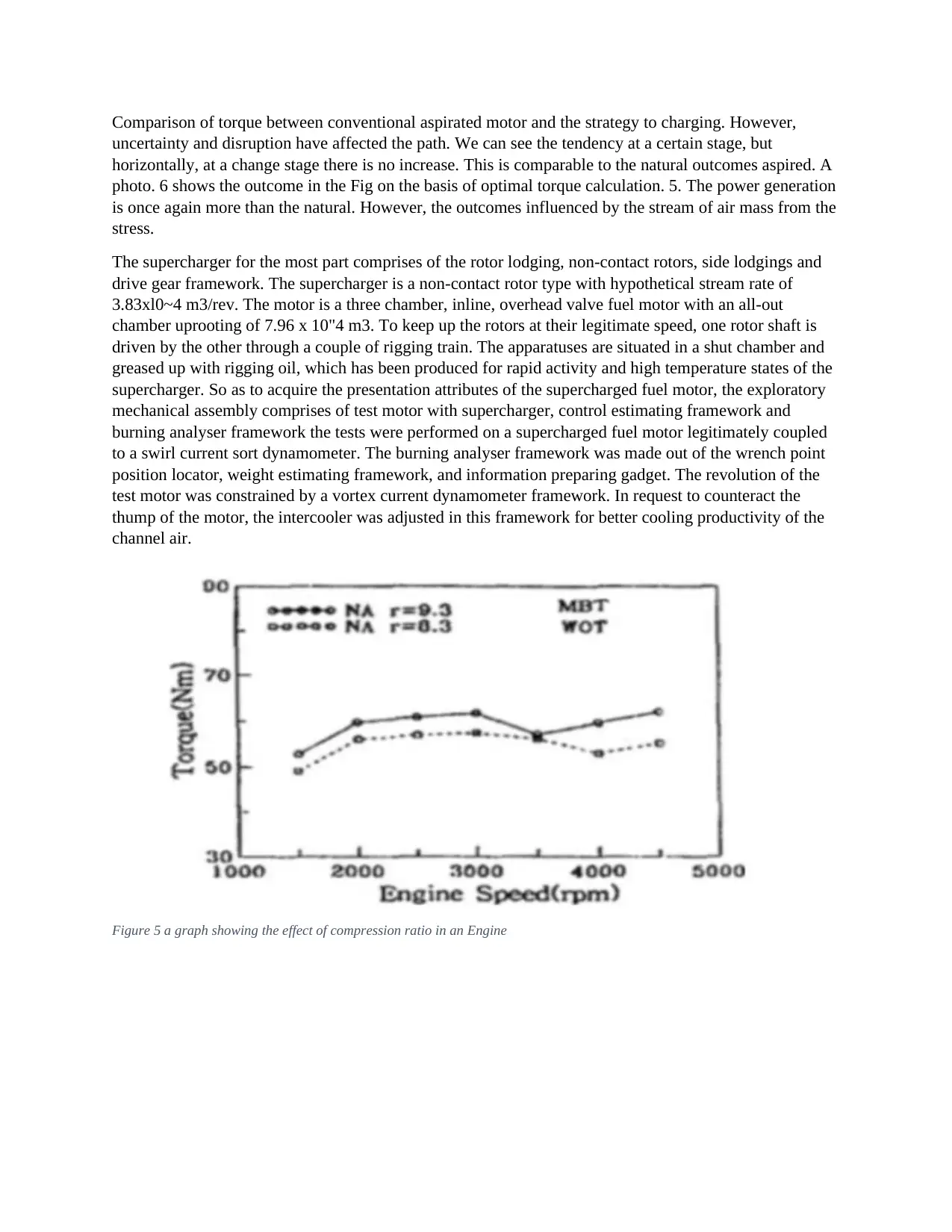
Comparison of torque between conventional aspirated motor and the strategy to charging. However,
uncertainty and disruption have affected the path. We can see the tendency at a certain stage, but
horizontally, at a change stage there is no increase. This is comparable to the natural outcomes aspired. A
photo. 6 shows the outcome in the Fig on the basis of optimal torque calculation. 5. The power generation
is once again more than the natural. However, the outcomes influenced by the stream of air mass from the
stress.
The supercharger for the most part comprises of the rotor lodging, non-contact rotors, side lodgings and
drive gear framework. The supercharger is a non-contact rotor type with hypothetical stream rate of
3.83xl0~4 m3/rev. The motor is a three chamber, inline, overhead valve fuel motor with an all-out
chamber uprooting of 7.96 x 10"4 m3. To keep up the rotors at their legitimate speed, one rotor shaft is
driven by the other through a couple of rigging train. The apparatuses are situated in a shut chamber and
greased up with rigging oil, which has been produced for rapid activity and high temperature states of the
supercharger. So as to acquire the presentation attributes of the supercharged fuel motor, the exploratory
mechanical assembly comprises of test motor with supercharger, control estimating framework and
burning analyser framework the tests were performed on a supercharged fuel motor legitimately coupled
to a swirl current sort dynamometer. The burning analyser framework was made out of the wrench point
position locator, weight estimating framework, and information preparing gadget. The revolution of the
test motor was constrained by a vortex current dynamometer framework. In request to counteract the
thump of the motor, the intercooler was adjusted in this framework for better cooling productivity of the
channel air.
Figure 5 a graph showing the effect of compression ratio in an Engine
⊘ This is a preview!⊘
Do you want full access?
Subscribe today to unlock all pages.
Trusted by 1+ million students worldwide
1 out of 26


Your All-in-One AI-Powered Toolkit for Academic Success.
+13062052269
info@desklib.com
Available 24*7 on WhatsApp / Email
![[object Object]](/_next/static/media/star-bottom.7253800d.svg)
Unlock your academic potential
Copyright © 2020–2026 A2Z Services. All Rights Reserved. Developed and managed by ZUCOL.