MITS5003 Wireless Communication Assignment: Signal Analysis

Verified

Added on  2022/08/31

|13
|1302
|25
Homework Assignment
AI Summary
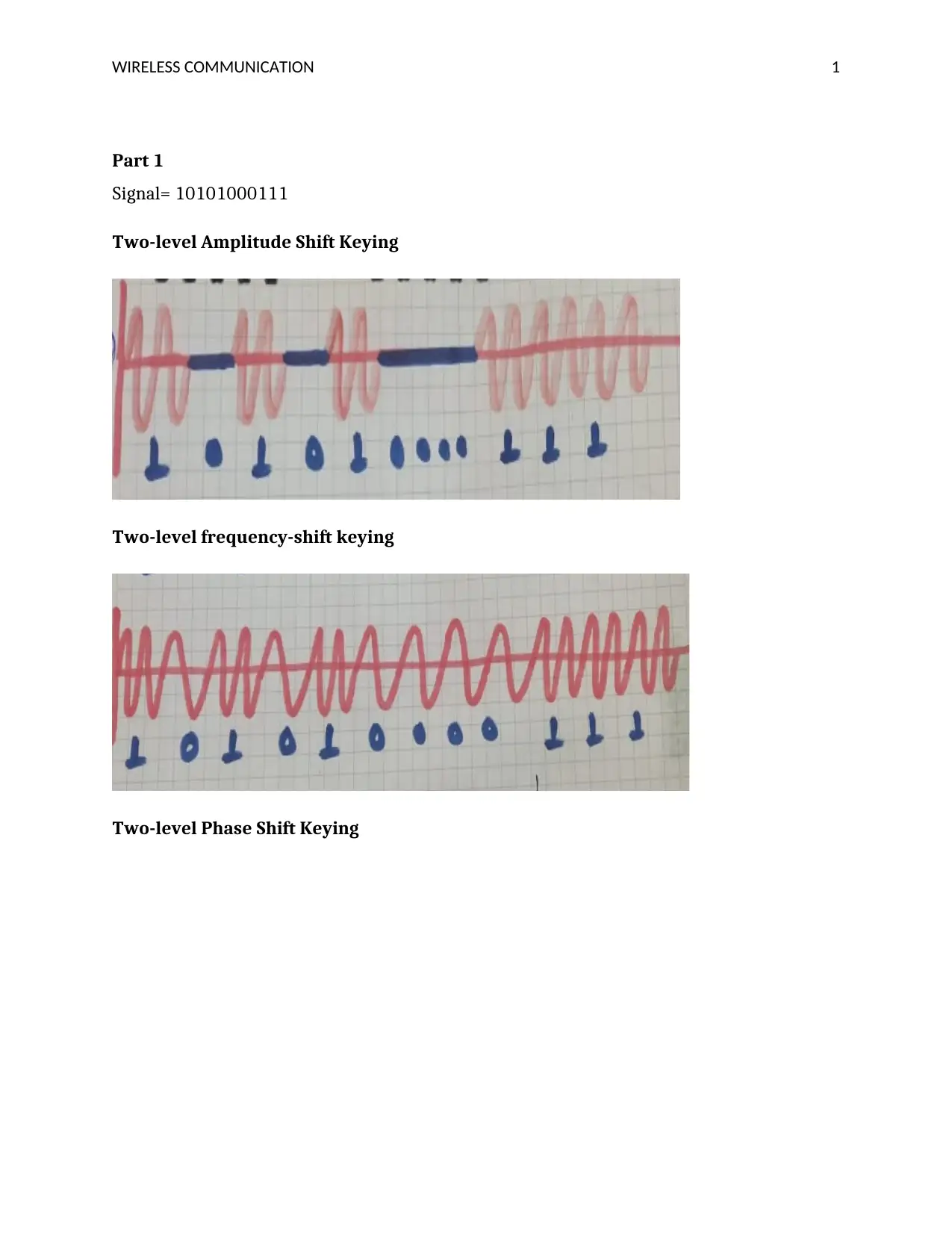
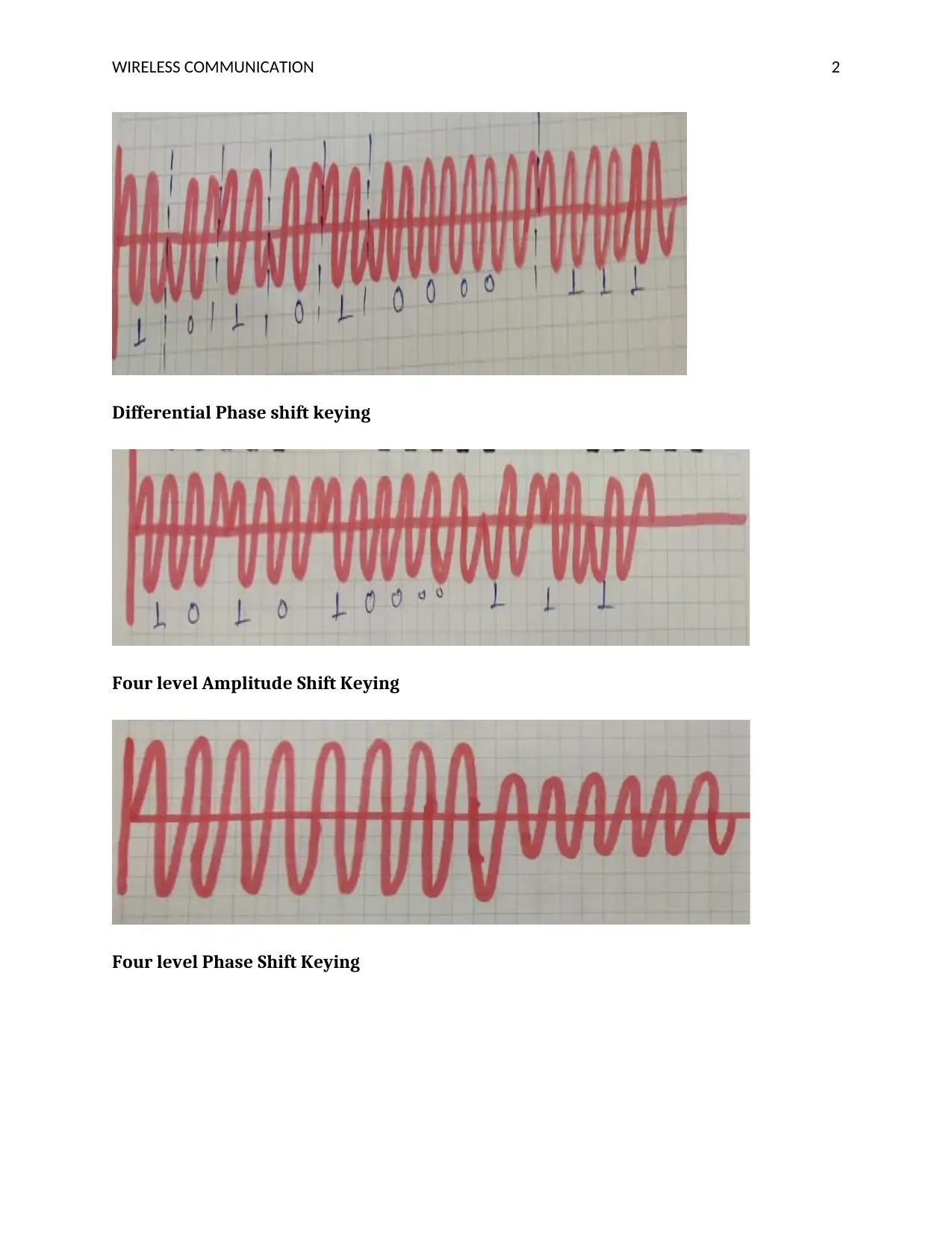
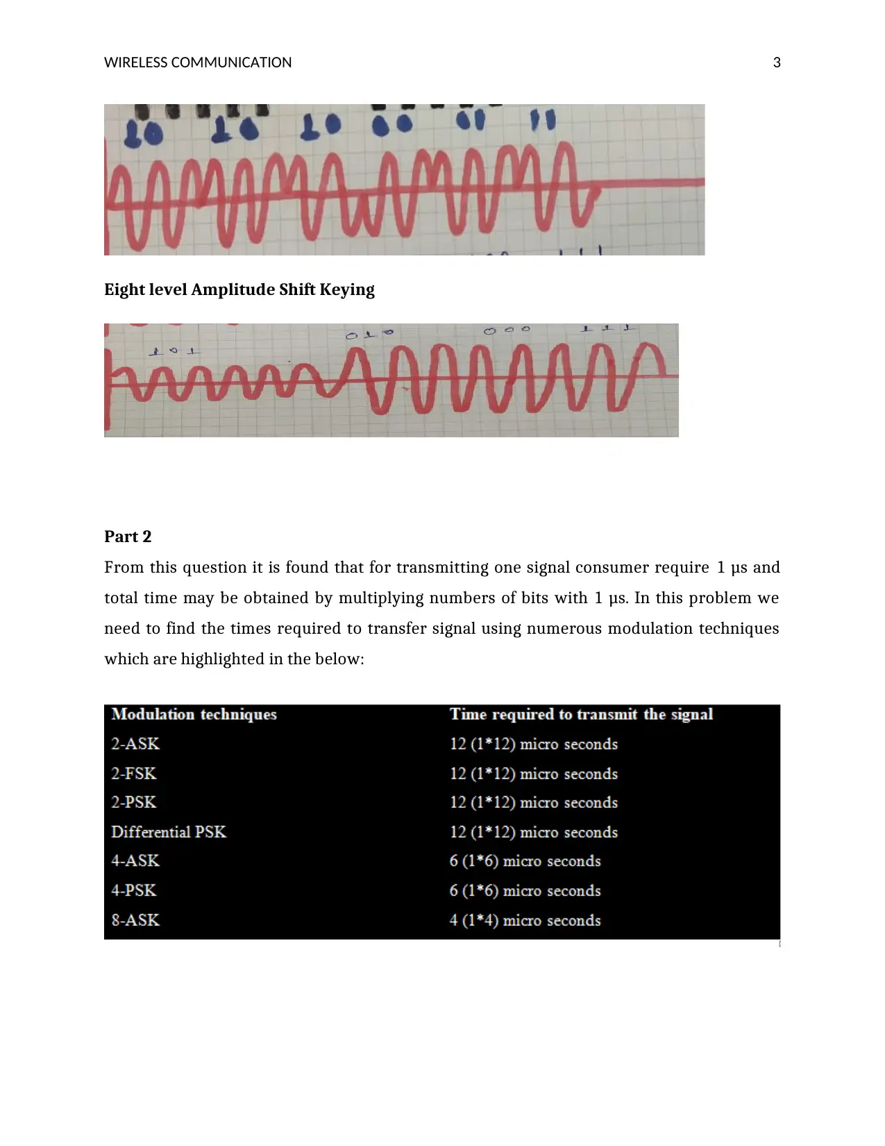
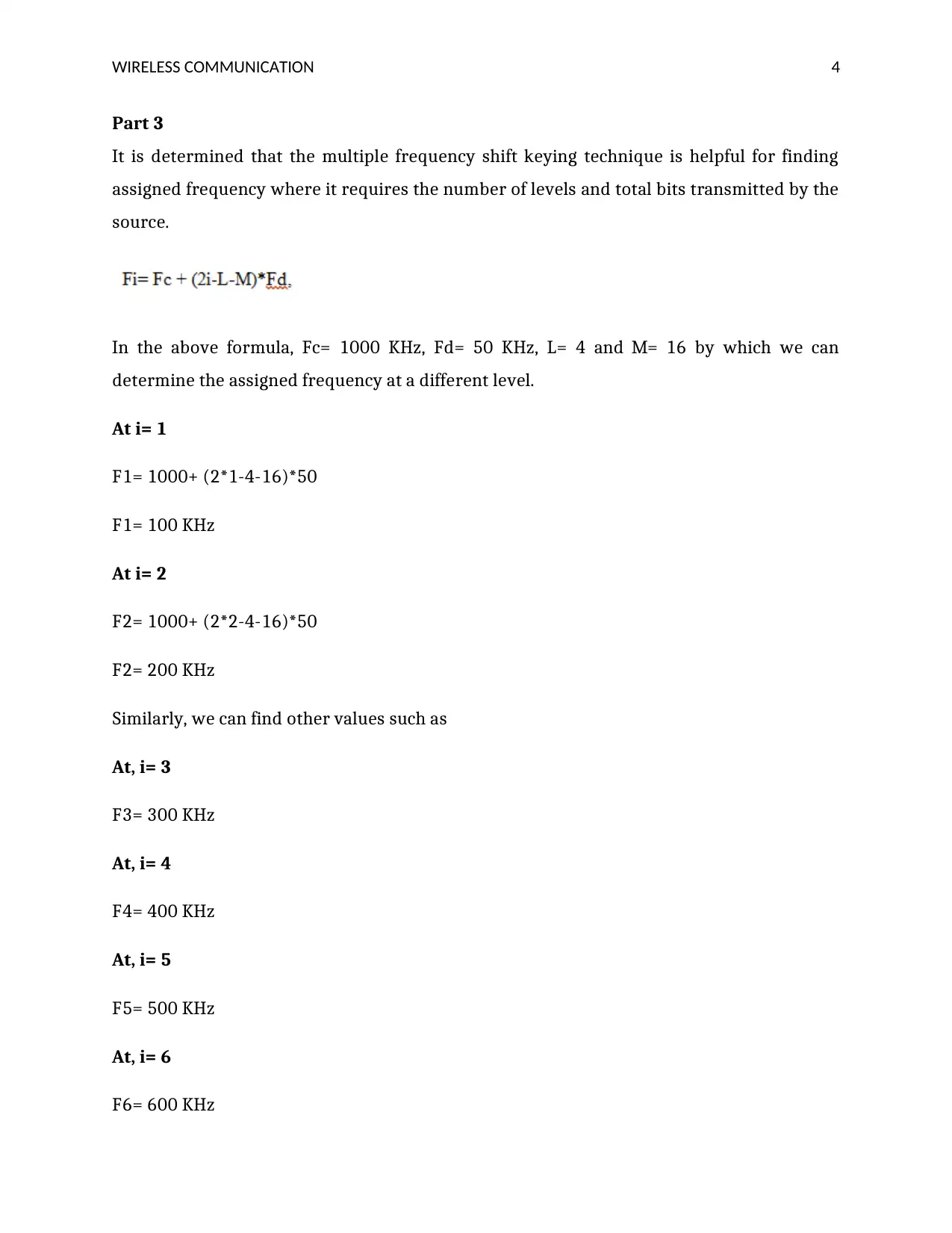
This document presents a comprehensive solution to a wireless communication assignment, addressing various aspects of the field. The solution begins with an analysis of different modulation techniques, including Two-level Amplitude Shift Keying, Frequency Shift Keying, Phase Shift Keying, and their multi-level variants. It then explores signal transmission times and the application of Multiple Frequency Shift Keying (MFSK) for frequency assignment. Further sections delve into analog and frequency modulation waveforms, followed by an examination of 8 QAM figures. The assignment also covers communication network handoff scenarios, analyzing signal strength and threshold values. Additionally, the solution explains the Cyclic Redundancy Check (CRC) method for error detection in communication networks. Finally, the document analyzes cell occupancy time, traffic intensity, and the advantages of hexagonal cell shapes in cellular communication, supported by relevant references.
tabler-icon-diamond-filled.svg

Contribute Materials

Your contribution can guide someone’s learning journey. Share your documents today.
Document Page
WIRELESS COMMUNICATION 0
MITS5003
tabler-icon-diamond-filled.svg

Secure Best Marks with AI Grader

Need help grading? Try our AI Grader for instant feedback on your assignments.
Document Page
WIRELESS COMMUNICATION 1
Part 1
Signal= 10101000111
Two-level Amplitude Shift Keying
Two-level frequency-shift keying
Two-level Phase Shift Keying
Document Page
WIRELESS COMMUNICATION 2
Differential Phase shift keying
Four level Amplitude Shift Keying
Four level Phase Shift Keying
Document Page
WIRELESS COMMUNICATION 3
Eight level Amplitude Shift Keying
Part 2
From this question it is found that for transmitting one signal consumer require 1 μs and
total time may be obtained by multiplying numbers of bits with 1 μs. In this problem we
need to find the times required to transfer signal using numerous modulation techniques
which are highlighted in the below:
tabler-icon-diamond-filled.svg

Secure Best Marks with AI Grader

Need help grading? Try our AI Grader for instant feedback on your assignments.
Document Page
WIRELESS COMMUNICATION 4
Part 3
It is determined that the multiple frequency shift keying technique is helpful for finding
assigned frequency where it requires the number of levels and total bits transmitted by the
source.
In the above formula, Fc= 1000 KHz, Fd= 50 KHz, L= 4 and M= 16 by which we can
determine the assigned frequency at a different level.
At i= 1
F1= 1000+ (2*1-4-16)*50
F1= 100 KHz
At i= 2
F2= 1000+ (2*2-4-16)*50
F2= 200 KHz
Similarly, we can find other values such as
At, i= 3
F3= 300 KHz
At, i= 4
F4= 400 KHz
At, i= 5
F5= 500 KHz
At, i= 6
F6= 600 KHz
Document Page
WIRELESS COMMUNICATION 5
At, i= 7
F7= 700 KHz
At, i=8
F8= 800 KHz
At, i=9
F9= 900 KHz
At, i= 10
F10= 1000 KHz
At, i= 11
F11= 1100 KHz
At, i= 12
F12= 1200 KHz
At, i= 13
F13= 1300 KHz
At, i= 14
F14= 1400 KHz
At, i= 15
F15= 1500 KHz
At, i= 16
F16= 1600 KHz
Document Page
WIRELESS COMMUNICATION 6
Answer 4
In the case of analog modulation (AM) transmitted signal is modulated using a larger
amplitude signal so that the receiver can obtain the appropriate signal with less noise and
error. On the other hand, frequency modulation (FM) is used to enhance the frequency of
the transmitted signal. As per the provided input signal, we can obtain AM modulated and
FM modulated waveforms that represented below:
Figure: Frequency waveform
Figure: Amplitude waveform
Part 5
The below image shows 8 QAM figure that contains two amplitude stages and 4 phase
stages:
tabler-icon-diamond-filled.svg

Paraphrase This Document

Need a fresh take? Get an instant paraphrase of this document with our AI Paraphraser
Document Page
WIRELESS COMMUNICATION 7
Part 6
The below diagram represents a communication network among base station A and base
station B where received signal at base station A is defined as SA and at base station B is
called as SB.
Section a
While considering relative signal strength the handoff can obtain at position A in the above
diagram due to larger strength of the signal.
Section b
Document Page
WIRELESS COMMUNICATION 8
While considering relative signal strength with threshold value TH1, the handoff takes
place at location L4.
Section c
As per the given information, signal strength is related to the threshold TH2 for which
handoff may produce at L3 location.
Section d
In which signal strength is associated with the threshold TH3 that means the handoff takes
place at base station A.
Section e
If the signal strength is linked with the hysteresis, the handoff may be considered at
location C
Section f
It is found that at base station A handoff will take place due to the presence of hysteresis
and threshold TH1 in the signal.
Section g
In which at base station A handoff takes place because hysteresis is associated with the
threshold TH2
Section h
As per the given information, both hysteresis and threshold TH3 are considered in the
signal due to which handoff takes place at location L1.
Part 7
Cyclic redundancy check (CRC)
Document Page
WIRELESS COMMUNICATION 9
It is a method used in the communication networks and channels for detecting errors using
binary division approach. CRC generator is a part of the CRC method which is mainly
represented as a bit pattern which can be gathered by taking the position of the bit and the
coefficient of the given binary signal [1]. There are various stages contain CRC techniques
which are analyzed below:
Step 1: calculation of CRC
A string of n number of zeros is appended to the system that needs to be transferred
In which n is one bit less than the provided signal?
The binary division process is used for obtaining results
After this process reminder is obtained that known as CRC [2].
Step 2: Appending CRC to data
The CRC signal is gathered after the binary division
The string of n number of zeros is appended to the data unit is finally replaced by
the CRC reminder
Step 3: transmission to the receiver
The formed code is now transferred to the receiver
Step 4: checking at the destination part
The received signal by the receiver is categorized with the similar CRC generator
On division, the remainder is checked and evaluated
If the remainder is 0 so the receiver will obtain an appropriate signal
If reminder value is not equal to zero that means the transmitted signal contains
several errors at the time of transmission
Part 8
A. Total occupied time is given below:
Time= 5+15+40+70+20= 150 minutes
tabler-icon-diamond-filled.svg

Secure Best Marks with AI Grader

Need help grading? Try our AI Grader for instant feedback on your assignments.
Document Page
WIRELESS COMMUNICATION 10
B. The total number of cells are given below:
Number of cells= 10+15+2+20+5= 50 cells
C. Mean occupied time/cell is given below:
Therefore, the mean occupied time= 5.800 min/cell
D. The mean rate is inversely proportional to the mean occupied time which is given
below:
Mean rate= 1/5.8= 0.7 cell/min
E. Traffic intensity is given below
For U1= 10 Erlangs (1*120+5/60)
For U2= 15 Erlangs (1*60+ 15/60)
For U3= 2 Erlangs (1*3+40/60)
For U4= 19.9 Erlangs (1*17.1+ 70/60)
For U5= 5 Erlangs (1*15+ 20/60)
So, traffic intensity= 10+15+2+19.9+5= 51.9 Erlangs
Document Page
WIRELESS COMMUNICATION 11
Part 9
Square and circle-shaped cells are not able to provide better services in the case of cellular
communication and distance among center and corner is larger which produce a problem
for delivering an equal level of signals at each cellular point [3]. Moreover, both square and
circle-shaped cells cannot be used for long-distance communication due to their limited
efficiency [4]. All these issues resolved by hexagonal shaped cells and provided a way
where communication can be performed effectively and larger geographical areas can be
covered.
Document Page
WIRELESS COMMUNICATION 12
References
[1].R., Prévost, M., Coulon, D., Bonacci, J., LeMaitre, J.P. Millerioux and, J.Y., Tourneret,
“Cyclic redundancy checkbased detection algorithms for automatic identification
system signals received by satellite,” International Journal of Satellite
Communications and Networking, vol. 31, no. 4, pp.157-176, 2013.
[2].H., Zhou, T. Ban and, J., Wang, “A cyclic redundancy checkbased noncoherent
receiver for automatic identification system signals,” International Journal of
Satellite Communications and Networking, vol. 34, no. 2, pp.251-261, 2016.
[3].K.B., Baltzis, “Hexagonal vs circular cell shape: a comparative analysis and
evaluation of the two popular modeling approximations,” Cellular Networks—
Positioning, Performance Analysis, Reliability, vol. 12, no. 8, pp.103-122, 2011.
[4].E., Kalantari, H. Yanikomeroglu and, A., Yongacoglu, “On the number and 3D
placement of drone base stations in wireless cellular networks,” In 2016 IEEE 84th
Vehicular Technology Conference (VTC-Fall), vol. 18, no. 6, pp. 1-6, 2016.
chevron_up_icon
1 out of 13
circle_padding
hide_on_mobile
zoom_out_icon
logo.png

Your All-in-One AI-Powered Toolkit for Academic Success.

Available 24*7 on WhatsApp / Email

[object Object]