University Communication Systems Homework Assignment Solutions
VerifiedAdded on 2020/04/15
|21
|3588
|165
Homework Assignment
AI Summary
This document presents a comprehensive set of solutions for a Communication Systems homework assignment. The solutions cover a wide range of topics including free space path loss calculations, analysis of local oscillators and image frequencies, and the determination of auto-correlation functions. The assignment also delves into cellular system concepts such as frequency reuse and multiple access techniques like FDMA, TDMA, and CDMA. Furthermore, the solutions include detailed calculations for power spectral density, noise figure analysis in cascaded systems, and the role of RF amplifiers and limiters in FM receivers. Finally, the assignment explores the concept of ergodic random processes.
0
Communication Systems
Communication Systems
Paraphrase This Document
Need a fresh take? Get an instant paraphrase of this document with our AI Paraphraser
Table of Contents
Problem-1.............................................................................................................................................2
(a) Free space path loss.............................................................................................................2
(b) Local oscillator.....................................................................................................................3
Determine the frequency ratio....................................................................................................3
Determine the image frequency..................................................................................................4
(c) Auto correlation function....................................................................................................4
Problem-2.............................................................................................................................................4
(a) Frequency re-use in cellular system.......................................................................................4
(b) Duplexer in cellular system.....................................................................................................6
(c) Multiple access technique........................................................................................................6
Problem-3.............................................................................................................................................9
(a) Find the power spectral density of the output Sy(f)..............................................................9
(b) Auto correlation of the output signal R(y)τ.........................................................................10
(c) Output signal p y....................................................................................................................10
Problem -4..........................................................................................................................................10
(a) Determine the overall noise figure of the cascade......................................................................10
(b) Input power..................................................................................................................................11
(c ) Suppose amplifier 1 and 2 are interchanged. the noise figure cascade is F1 =6,F2=0............11
Problem- 5..........................................................................................................................................11
(a)Overall nosie factor......................................................................................................................11
(b)The overall noise figure if a preamplifier....................................................................................12
( c) The overall noise figure if the amplifier.....................................................................................12
Problem -6..........................................................................................................................................12
(a) Auto correlation function......................................................................................................12
(b) Power spectral density...........................................................................................................12
Problem – 7........................................................................................................................................12
(a) Briefly explain the role of the blocks labelled RF amplifier and Limiter in the diagram.......12
(b) Find the bandwidths required for the RF amplifier, IF amplifier, and of the audio
amplifier.............................................................................................................................................15
(c) Larger bandwidth..................................................................................................................16
Problem- 8..........................................................................................................................................16
(a) Briefly explain what is meant by an ergodic random process............................................16
(b) Determine whether or not the random process X (t) is an ergodic random process.........17
(c) Random process is uniformly distribution is X (t) an ergodic random process................18
References..........................................................................................................................................19
⊘ This is a preview!⊘
Do you want full access?
Subscribe today to unlock all pages.
Trusted by 1+ million students worldwide
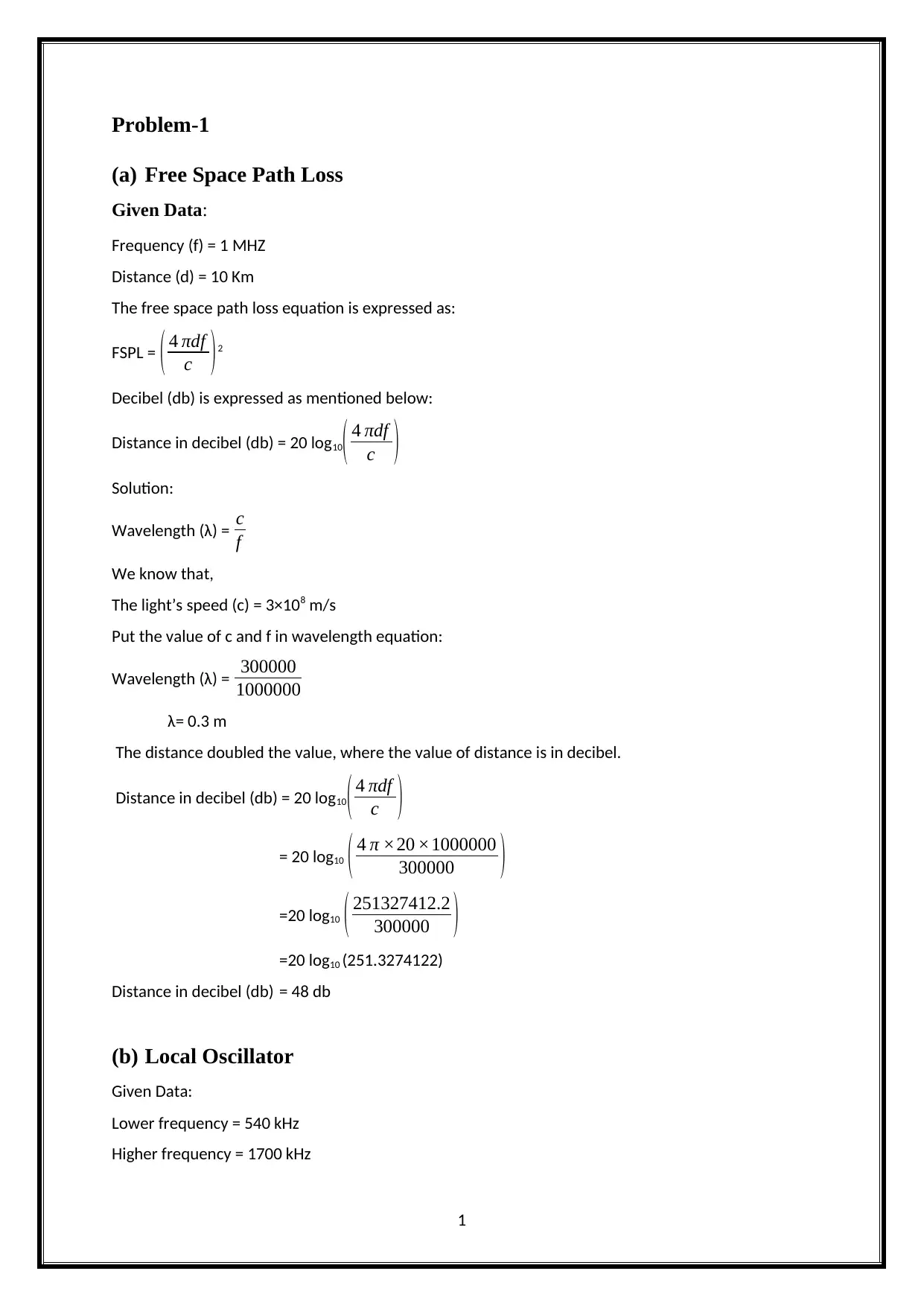
Problem-1
(a) Free Space Path Loss
Given Data:
Frequency (f) = 1 MHZ
Distance (d) = 10 Km
The free space path loss equation is expressed as:
FSPL = ( 4 πdf
c )2
Decibel (db) is expressed as mentioned below:
Distance in decibel (db) = 20 log10( 4 πdf
c )
Solution:
Wavelength (λ) = c
f
We know that,
The light’s speed (c) = 3×10⁸ m/s
Put the value of c and f in wavelength equation:
Wavelength (λ) = 300000
1000000
λ= 0.3 m
The distance doubled the value, where the value of distance is in decibel.
Distance in decibel (db) = 20 log10
( 4 πdf
c )
= 20 log10 ( 4 π ×20 ×1000000
300000 )
=20 log10 ( 251327412.2
300000 )
=20 log10 (251.3274122)
Distance in decibel (db) = 48 db
(b) Local Oscillator
Given Data:
Lower frequency = 540 kHz
Higher frequency = 1700 kHz
1
Paraphrase This Document
Need a fresh take? Get an instant paraphrase of this document with our AI Paraphraser
Intermediate frequency (IF) = 455 kHz
Solution:
Determine the Frequency Ratio
The frequency ratio is defined by the highest to lowest frequency ratio of the local
oscillator frequency fLO. Local oscillator frequency ratio is the difference between the
highest ratio and the lowest ratio.
fLO = highest ratio – lowest ratio/2
= 1700-540/2
=1160/2
Ratio = 580
Determine the Image Frequency
To find the value of frequency (f),
F = 1
2 π √ LC
= 1
2 π √ 109
= 1
65.59
= 0.01524
Image frequency (fimg)
fimg = { f +2 f IF if fLO > f (high side injection) }, { f −2 f IF if fLO <f (low side injection) }
= { (0.0152) + 2 (45), (0.0152) – 2 (45)
= {90.0152 , -89.984
Image frequency in fall time = 90.0152
(c) Auto Correlation Function
The appropriate autocorrelation function is characterised as follows,
Autocorrelation function ρ(h) = γ(h)/ γ(0)
| ρ(h)| ≤ 1
Therefore, the appropriate autocorrelation function is given by the following equation, R(
τ ) = {1−|τ |,∨τ∨≤ 1
1+|τ | ,∨τ ∨≥1
2
Problem-2
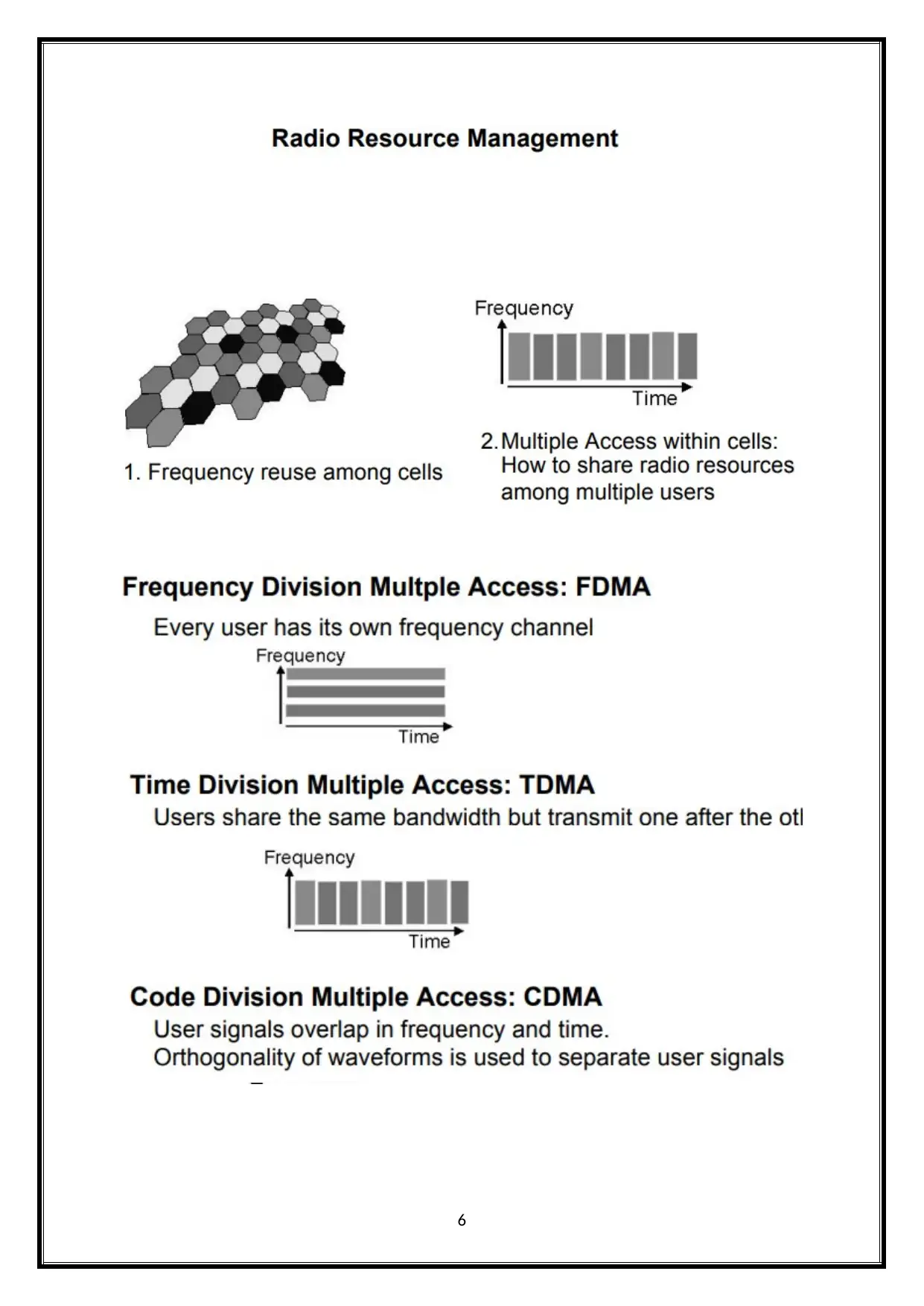
(a) Frequency re-use in Cellular System
Cellular Frequency Reuse- Principles
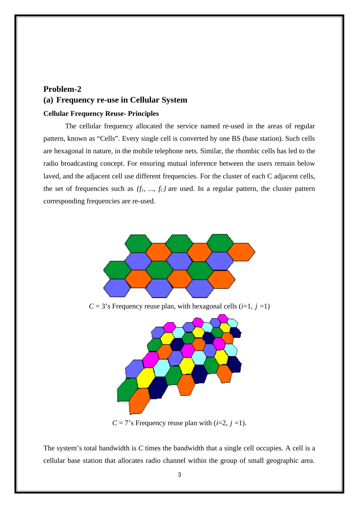
The cellular frequency allocated the service named re-used in the areas of regular
pattern, known as “Cells”. Every single cell is converted by one BS (base station). Such cells
are hexagonal in nature, in the mobile telephone nets. Similar, the rhombic cells has led to the
radio broadcasting concept. For ensuring mutual inference between the users remain below
laved, and the adjacent cell use different frequencies. For the cluster of each C adjacent cells,
the set of frequencies such as {f1, ..., fC} are used. In a regular pattern, the cluster pattern
corresponding frequencies are re-used.
C = 3’s Frequency reuse plan, with hexagonal cells (i=1, j =1)
C = 7’s Frequency reuse plan with (i=2, j =1).
The system’s total bandwidth is C times the bandwidth that a single cell occupies. A cell is a
cellular base station that allocates radio channel within the group of small geographic area.
3
(a) Frequency re-use in Cellular System
Cellular Frequency Reuse- Principles
The cellular frequency allocated the service named re-used in the areas of regular
pattern, known as “Cells”. Every single cell is converted by one BS (base station). Such cells
are hexagonal in nature, in the mobile telephone nets. Similar, the rhombic cells has led to the
radio broadcasting concept. For ensuring mutual inference between the users remain below
laved, and the adjacent cell use different frequencies. For the cluster of each C adjacent cells,
the set of frequencies such as {f1, ..., fC} are used. In a regular pattern, the cluster pattern
corresponding frequencies are re-used.
C = 3’s Frequency reuse plan, with hexagonal cells (i=1, j =1)
C = 7’s Frequency reuse plan with (i=2, j =1).
The system’s total bandwidth is C times the bandwidth that a single cell occupies. A cell is a
cellular base station that allocates radio channel within the group of small geographic area.
3
⊘ This is a preview!⊘
Do you want full access?
Subscribe today to unlock all pages.
Trusted by 1+ million students worldwide
The neighbouring cells have been assigned with distinct channel groups. Therefore, these
channel groups could be reused for covering various cells, with certain courage limits within
the cell’s boundary.
It is called frequency reuse or frequency planning.
Frequency re-use factor=1/N, where each cell present in a cluster is just assigned 1/N of the
total available channels in the system.
Cluster Size
Factor N is known as cluster.
At each N cell, the frequency is being reused.
Every single cell assignment is k=S/N
N cells/cluster
It connects without any gaps.
Certain values are needed for the hexagonal geometry.
N= i2+ij+ j2 where i,j≥1
Advantage
1) Increased capacity
2) Limited spectrum is required.
3) Same spectrum may be allocated to other network.
4) The frequency reuse system can increase the spectrum efficiency, thereby increasing
the system’s capacity.
5) Homogeneity sample
Disadvantage
a) If a system is not properly designed, co-channel inference might occur due to
simultaneous use of the same channel.
b) Hard to maintain.
c) Dedifferentiation
d) Instability and aneuploidy.
e) Only grow small amount of tissue at high cost.
4
Paraphrase This Document
Need a fresh take? Get an instant paraphrase of this document with our AI Paraphraser
(b) Duplexer in Cellular System
It is electronic device which permits bi-directional (duplex) communication in a
single path. The radio communication system in radar isolates the transmitter from the
receiver, and allows sharing a common antenna. The radio repeater consists of a duplexer,
which might be based on frequency, polarization or timing.
To have two way communication (both voice and data), duplexing helps. It can allow
simultaneously to listen and talk.
The frequency or time domain technique can be used for duplexing.
The TDMA is a wired network, which uses high speed local area networking over the
existing home wiring. Thus, it can’t be utilized as duplex, in the celluar system.
(c) Multiple Access Technique
The multiple access technique is used to permit wide range of mobile users for
effectively sharing the allocated spectrum. The spectrum limited is sharing is required to
capacity cell increased the available band width to use at the same time by different users.
Multiple Access Techniques for Wireless Communication
The wireless communication system sends information to the BS, after receiving
information from the BS. Cellular system divides the given area into cells, like mobile units
in each communication cell with BS. The cellular system’s objective is to maximize the
channel’s capacity. It handles large number of calls, in sufficient level of quality service’s
bandwidth. These are various methods to permit the channels to have access.
The most used techniques are:
1) Frequency division multiple-access (FDMA)
2) Code division multiple-access (CDMA)
3) Time division multiple-access (TDMA)
5
6
⊘ This is a preview!⊘
Do you want full access?
Subscribe today to unlock all pages.
Trusted by 1+ million students worldwide
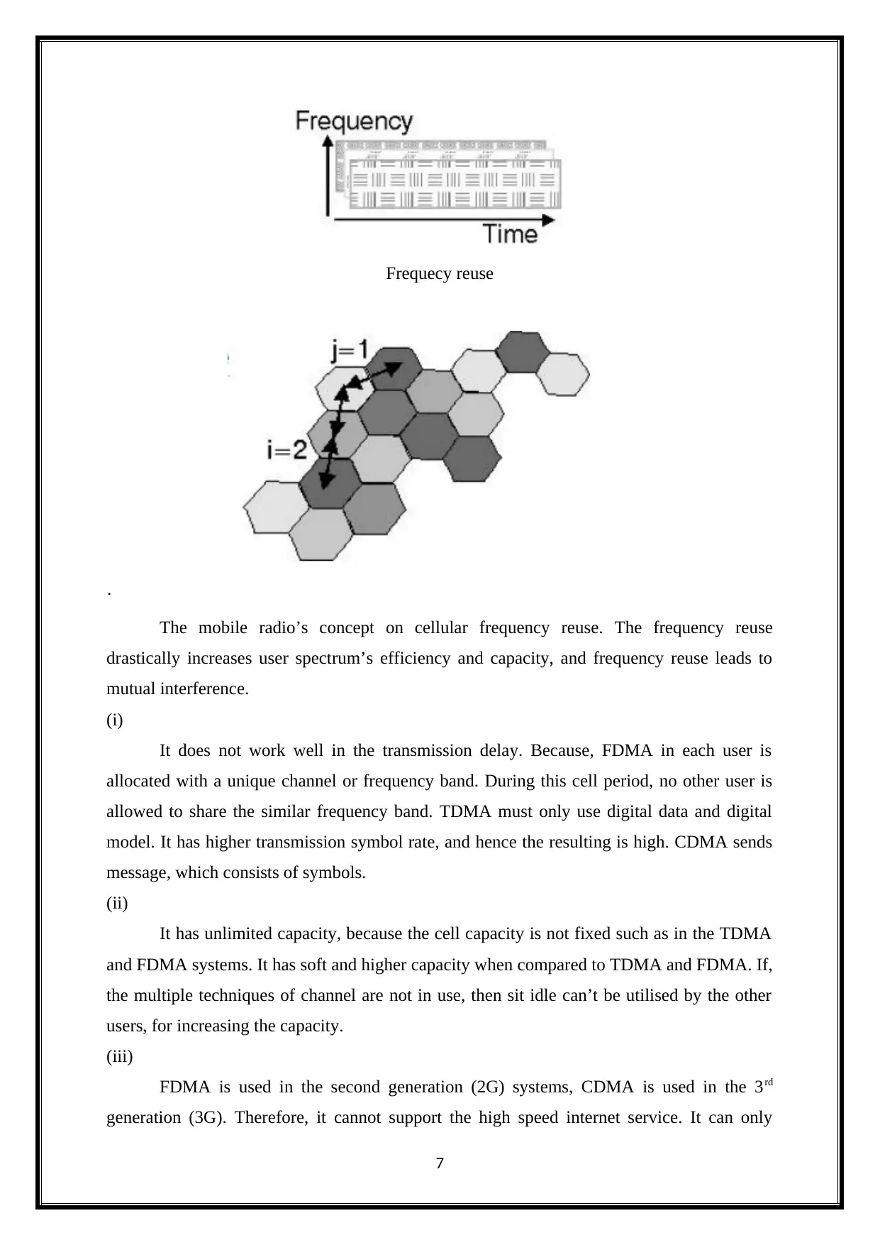
Frequecy reuse
·
The mobile radio’s concept on cellular frequency reuse. The frequency reuse
drastically increases user spectrum’s efficiency and capacity, and frequency reuse leads to
mutual interference.
(i)
It does not work well in the transmission delay. Because, FDMA in each user is
allocated with a unique channel or frequency band. During this cell period, no other user is
allowed to share the similar frequency band. TDMA must only use digital data and digital
model. It has higher transmission symbol rate, and hence the resulting is high. CDMA sends
message, which consists of symbols.
(ii)
It has unlimited capacity, because the cell capacity is not fixed such as in the TDMA
and FDMA systems. It has soft and higher capacity when compared to TDMA and FDMA. If,
the multiple techniques of channel are not in use, then sit idle can’t be utilised by the other
users, for increasing the capacity.
(iii)
FDMA is used in the second generation (2G) systems, CDMA is used in the 3rd
generation (3G). Therefore, it cannot support the high speed internet service. It can only
7
Paraphrase This Document
Need a fresh take? Get an instant paraphrase of this document with our AI Paraphraser
support limited number of users. Because, of the limitations in the numbers of orthogonal
resource blocks. This limits the current network’s SE and capacity, for supporting largely.
Problem-3
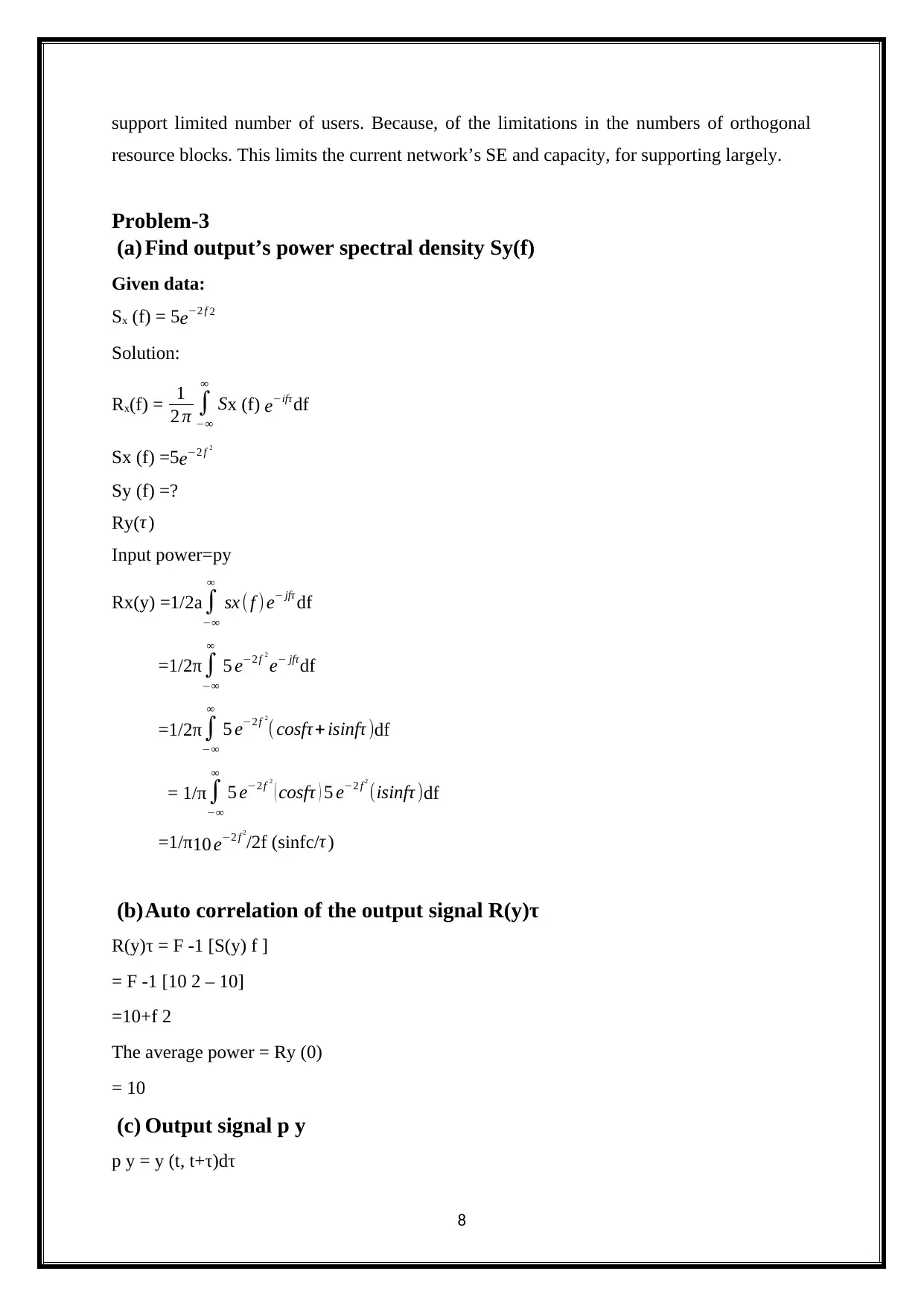
(a) Find output’s power spectral density Sy(f)
Given data:
Sx (f) = 5e−2 f 2
Solution:
Rx(f) = 1
2 π ∫
−∞
∞
Sx (f) e−ifτ df
Sx (f) =5e−2 f 2
Sy (f) =?
Ry(τ )
Input power=py
Rx(y) =1/2a ∫
−∞
∞
sx ( f ) e− jfτ df
=1/2π∫
−∞
∞
5 e−2 f 2
e− jfτdf
=1/2π ∫
−∞
∞
5 e−2 f 2
( cosfτ+ isinfτ )df
= 1/π∫
−∞
∞
5 e−2 f 2
( cosfτ ) 5 e−2 f 2
(isinfτ )df
=1/π10 e−2 f 2
/2f (sinfc/τ )
(b)Auto correlation of the output signal R(y)τ
R(y)τ = F -1 [S(y) f ]
= F -1 [10 2 – 10]
=10+f 2
The average power = Ry (0)
= 10
(c) Output signal p y
p y = y (t, t+τ)dτ
8
resource blocks. This limits the current network’s SE and capacity, for supporting largely.
Problem-3
(a) Find output’s power spectral density Sy(f)
Given data:
Sx (f) = 5e−2 f 2
Solution:
Rx(f) = 1
2 π ∫
−∞
∞
Sx (f) e−ifτ df
Sx (f) =5e−2 f 2
Sy (f) =?
Ry(τ )
Input power=py
Rx(y) =1/2a ∫
−∞
∞
sx ( f ) e− jfτ df
=1/2π∫
−∞
∞
5 e−2 f 2
e− jfτdf
=1/2π ∫
−∞
∞
5 e−2 f 2
( cosfτ+ isinfτ )df
= 1/π∫
−∞
∞
5 e−2 f 2
( cosfτ ) 5 e−2 f 2
(isinfτ )df
=1/π10 e−2 f 2
/2f (sinfc/τ )
(b)Auto correlation of the output signal R(y)τ
R(y)τ = F -1 [S(y) f ]
= F -1 [10 2 – 10]
=10+f 2
The average power = Ry (0)
= 10
(c) Output signal p y
p y = y (t, t+τ)dτ
8
= 10 [cosτ- isinτ +cosτ+ isinτ]
=10 2cosT
=20 cosT
Problem -4
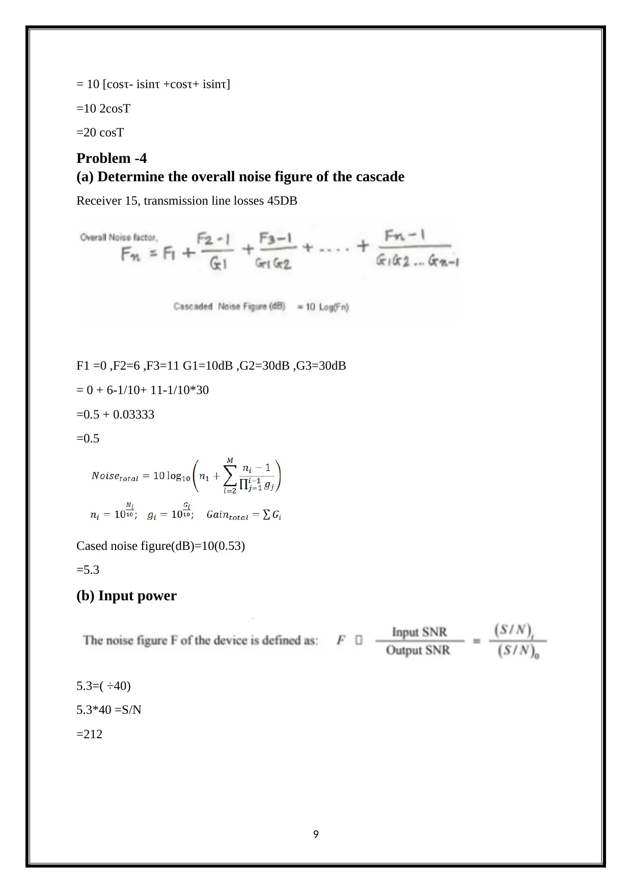
(a) Determine the overall noise figure of the cascade
Receiver 15, transmission line losses 45DB
F1 =0 ,F2=6 ,F3=11 G1=10dB ,G2=30dB ,G3=30dB
= 0 + 6-1/10+ 11-1/10*30
=0.5 + 0.03333
=0.5
Cased noise figure(dB)=10(0.53)
=5.3
(b) Input power
5.3=( ÷40)
5.3*40 =S/N
=212
9
=10 2cosT
=20 cosT
Problem -4
(a) Determine the overall noise figure of the cascade
Receiver 15, transmission line losses 45DB
F1 =0 ,F2=6 ,F3=11 G1=10dB ,G2=30dB ,G3=30dB
= 0 + 6-1/10+ 11-1/10*30
=0.5 + 0.03333
=0.5
Cased noise figure(dB)=10(0.53)
=5.3
(b) Input power
5.3=( ÷40)
5.3*40 =S/N
=212
9
⊘ This is a preview!⊘
Do you want full access?
Subscribe today to unlock all pages.
Trusted by 1+ million students worldwide
1 out of 21
Your All-in-One AI-Powered Toolkit for Academic Success.
+13062052269
info@desklib.com
Available 24*7 on WhatsApp / Email
![[object Object]](/_next/static/media/star-bottom.7253800d.svg)
Unlock your academic potential
Copyright © 2020–2026 A2Z Services. All Rights Reserved. Developed and managed by ZUCOL.