ELEC3500 Telecommunications Networks Simulation Experiment Report

Verified

Added on  2023/06/03

|14
|1991
|170
Report
AI Summary
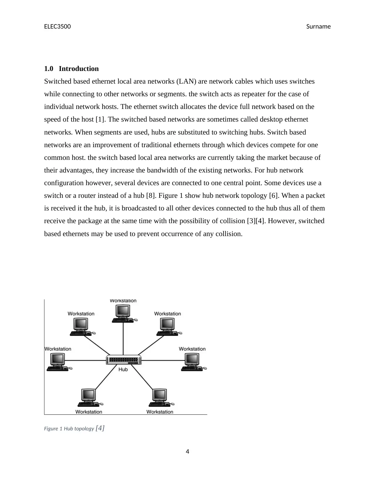
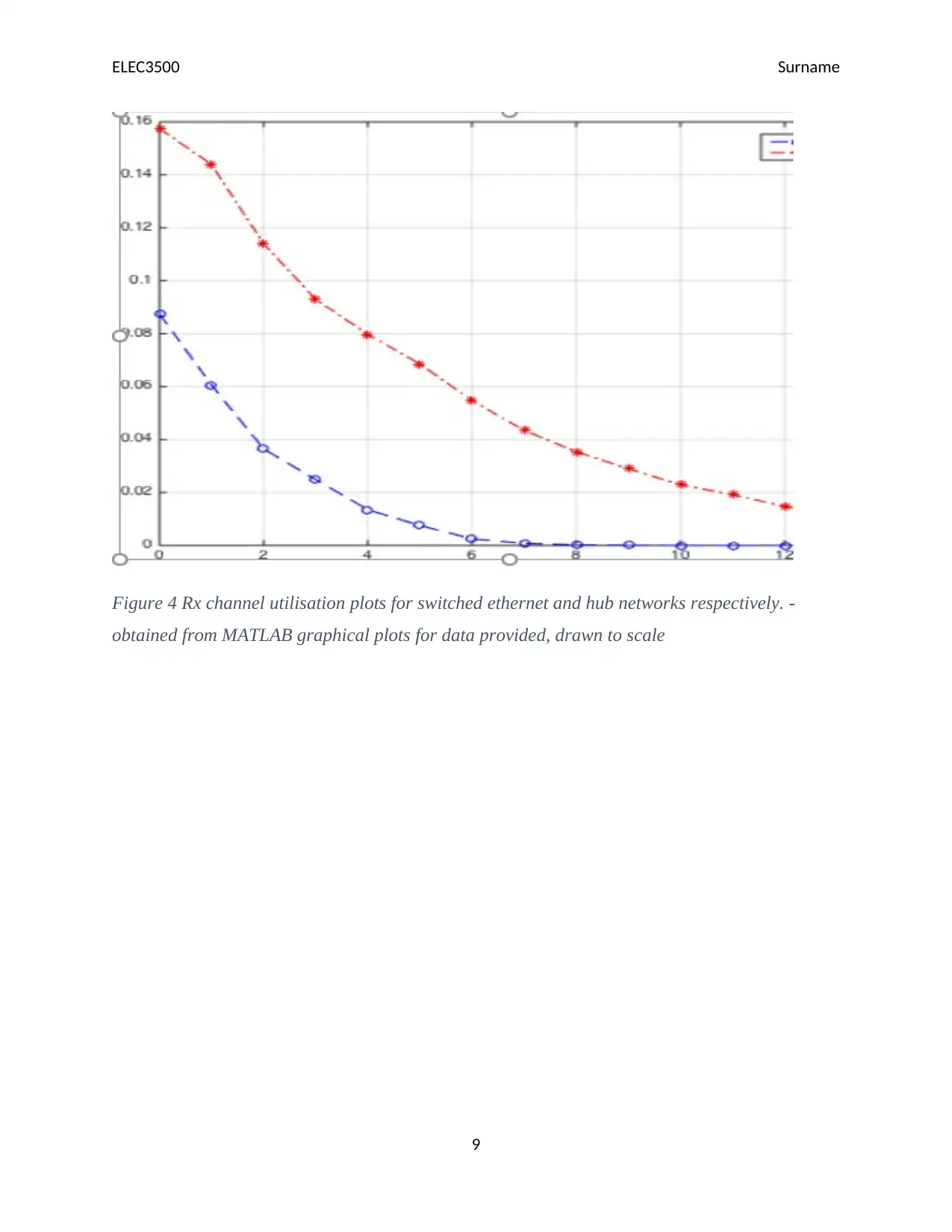
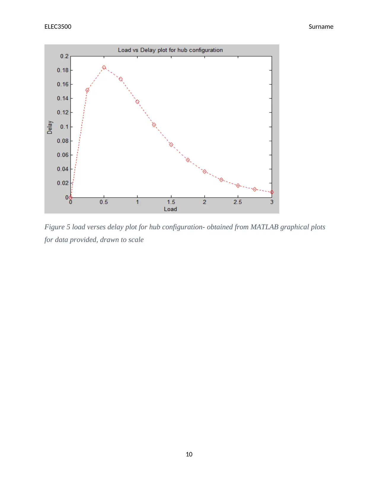
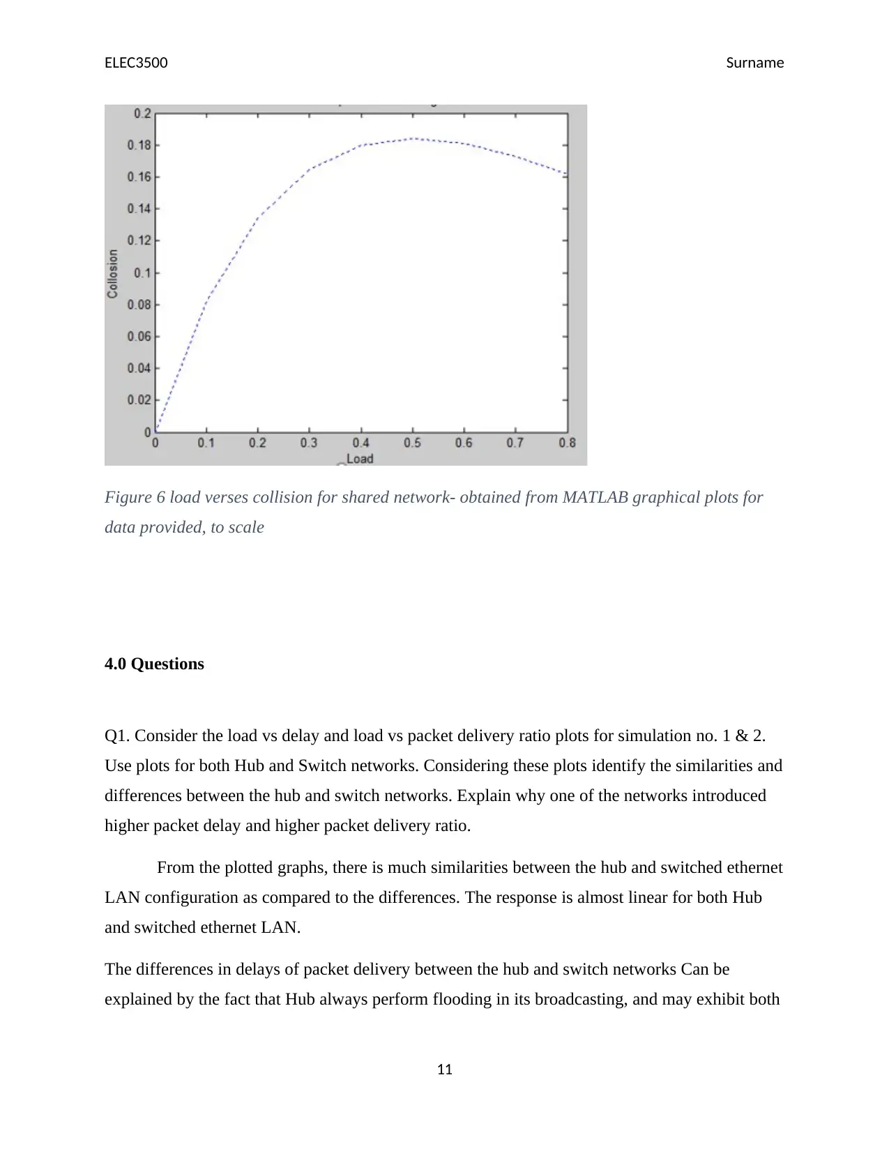
This report presents an analysis of the Quality of Service (QoS) performance of Hub and Switched based Ethernet Local Area Networks (LANs) using OMNET++ simulation models. The experiment, conducted for the ELEC3500 course at Monash University, investigates the impact of network topology and packet length on key performance indicators such as packet delay, channel utilization, and collision rates. The methodology involves simulating client-server applications with varying traffic loads and packet sizes, comparing the results obtained from Hub and Switched network configurations. The findings, presented through graphical plots, reveal similarities and differences in network behavior, with the Switched network demonstrating superior performance in terms of reduced collisions and improved packet delivery ratio compared to the Hub network. The report also addresses specific questions regarding the influence of packet length on collision levels, the reasons for differences in packet delivery ratios, and the factors contributing to end-to-end delay in both network types. The conclusion highlights the advantages of Switched Ethernet LANs in minimizing collisions and enhancing overall network performance.
Document Page
ELEC3500 Surname
Monash University
Faculty of Engineering
ELEC3500 Telecommunications Networks
Simulation experiment V: comparing the QoS performances of Hub and Switched based
Ethernet LAN using OMNET++ simulation models
Student’s Name:
Registration Number:
Date:
1
tabler-icon-diamond-filled.svg

Paraphrase This Document

Need a fresh take? Get an instant paraphrase of this document with our AI Paraphraser
Document Page
ELEC3500 Surname
Summary
This experiment evaluates the quality of service (QoS) performance of Hub and the switched
based local area networks wick varying sizes of QoS packets depending on the parameters
provided, the previous simulations are also used as reference for this simulation V. Carrier sense
multiple access with collision detection (CSMA/CD) networks are mostly used to control access
in Ethernets for local area networks (LAN). It immediately terminates the transmission of any
data or information upon detection of any collision. In this lab experiment, the performance of
bus and hub configurations based CSMA/CD networks are analyzed using OMNET++
simulation models that were developed previously [5][2]
2
Document Page
ELEC3500 Surname
Contents
Summary....................................................................................................................................................2
1.0 Introduction...................................................................................................................................2
2.0 Methodology.........................................................................................................................................4
2.1 Objectives.........................................................................................................................................4
2.2 Model description............................................................................................................................4
2.3 Procedure.........................................................................................................................................5
2.0 Results and discussion...................................................................................................................6
4.0 Questions..............................................................................................................................................8
5.0 Conclusion............................................................................................................................................9
6.0 References............................................................................................................................................9
3
Document Page
ELEC3500 Surname
1.0 Introduction
Switched based ethernet local area networks (LAN) are network cables which uses switches
while connecting to other networks or segments. the switch acts as repeater for the case of
individual network hosts. The ethernet switch allocates the device full network based on the
speed of the host [1]. The switched based networks are sometimes called desktop ethernet
networks. When segments are used, hubs are substituted to switching hubs. Switch based
networks are an improvement of traditional ethernets through which devices compete for one
common host. the switch based local area networks are currently taking the market because of
their advantages, they increase the bandwidth of the existing networks. For hub network
configuration however, several devices are connected to one central point. Some devices use a
switch or a router instead of a hub [8]. Figure 1 show hub network topology [6]. When a packet
is received it the hub, it is broadcasted to all other devices connected to the hub thus all of them
receive the package at the same time with the possibility of collision [3][4]. However, switched
based ethernets may be used to prevent occurrence of any collision.
Figure 1 Hub topology [4]
4
tabler-icon-diamond-filled.svg

Paraphrase This Document

Need a fresh take? Get an instant paraphrase of this document with our AI Paraphraser
Document Page
ELEC3500 Surname
Figure 2 switched based network topology [5]
2.0 Methodology
2.1 Objectives
The objectives of this experiment were as stated below
1. To understand the basic principles in knowing the quality of service (QoS) of HUB
performance and switch based ethernet.
2. To utilize OMNET++ simulation models to analyse quality of service performance of
Hub and switched based ethernet LAN
3. Compare QoS (Quality of Service) performances of Hub and Switched based Ethernet
LANs.
4. to study the effect of packet length on the LAN QoS performances.
5
Document Page
ELEC3500 Surname
2.2 Model description
The Ethernet LAN simulation model implements a client server application, where host 0 is the
server and rest of the terminals are clients. Clients will send requests in the form of Ethernet
packets to obtain a reply from the server. Total traffic flow in the network will be twice the
number of packets generated by all client terminals in the network. Client and server packet sizes
are selectable from the omnetpp.ini file. Simulation parameters are listed in the table 1 below.
Simulation Parameters Value
Transmission rate: R 10 Mbits/sec
Simulation length 300 sec
Packet length: L Client: 200B, Server: 800B (Simulation 1) Client:
200B, Server: 1200B (Simulation 2)
Simulatio
n No.
Simulation Parameters Results to collect
Scalar
1 No of clients: 5, server: 1,
(number is in *.ini file).
Traffic load: 50, 75, 100, 125,
150, 175, 200
packets/sec/node. Run
simulation for both Hub and
Switched network models.
Mean end-to-end client packet delay, Rx channel
utilisation and Rx channel collision, Send &
receive packets (mac layer)
2 Change the server packet
length to 1200B. Calculate the
traffic load in packets/sec to
generate same amount of load
as simulation 1. For example,
As above
6
Document Page
ELEC3500 Surname
for
1200B packet size 35.7
packets/sec will generate same
load as 50 packets/sec using
800B packet size.
2.3 Procedure
The previously developed OMNET++ simulation models found in the ELEC3500 folder were
utilized in this experiment. By selecting a model in the run window, the model was run both in
the Hub and switched LAN mode. In cases of Bus configurations mode, the comments of the bus
networks were made to reduce the initial start time.
Using the Hub and switched network model configurations made above, the simulation 1 and 2
below were performed. Parameters used for simulation were as shown on table 1 and 2 under the
model description.
For simulation 1, scalar data was obtained from tables 1 and 2, this was needed to plot mean
packet delay, channel utilisation, collision utilisation and packet delivery ratio against the traffic
load for both networks. The packet delivery ratio was defined as the ratio of number of packets
received from the server to the request packets to server from client. All models developed in
this case ensured that every node transmitting request packet received a packet back from server.
For simulation 2, the packet length was changed and the traffic load set as that of simulation 1.
This simulation was to evaluate the effects of increasing the packet length on performance of
networks.
7
tabler-icon-diamond-filled.svg

Paraphrase This Document

Need a fresh take? Get an instant paraphrase of this document with our AI Paraphraser
Document Page
ELEC3500 Surname
2.0 Results and discussion
The results for the above experiment were represented in graphical plots using MATLAB, the
figures 3,4,5,6 represents the results.
Figure 3. Load verses collisions plot for Hub network – obtained from MATLAB graphical plots
for data provided, drawn to scale
8
Document Page
ELEC3500 Surname
Figure 4 Rx channel utilisation plots for switched ethernet and hub networks respectively. -
obtained from MATLAB graphical plots for data provided, drawn to scale
9
Document Page
ELEC3500 Surname
Figure 5 load verses delay plot for hub configuration- obtained from MATLAB graphical plots
for data provided, drawn to scale
10
tabler-icon-diamond-filled.svg

Paraphrase This Document

Need a fresh take? Get an instant paraphrase of this document with our AI Paraphraser
Document Page
ELEC3500 Surname
Figure 6 load verses collision for shared network- obtained from MATLAB graphical plots for
data provided, to scale
4.0 Questions
Q1. Consider the load vs delay and load vs packet delivery ratio plots for simulation no. 1 & 2.
Use plots for both Hub and Switch networks. Considering these plots identify the similarities and
differences between the hub and switch networks. Explain why one of the networks introduced
higher packet delay and higher packet delivery ratio.
From the plotted graphs, there is much similarities between the hub and switched ethernet
LAN configuration as compared to the differences. The response is almost linear for both Hub
and switched ethernet LAN.
The differences in delays of packet delivery between the hub and switch networks Can be
explained by the fact that Hub always perform flooding in its broadcasting, and may exhibit both
11
Document Page
ELEC3500 Surname
unicast and multitask networking, the switch networks performs the broadcasting first, then the
unicast and multicast of packets will depend on the feedback from the client.
Q2. Consider the Rx channel utilisation plots for simulation 1 and 2 for both networks. Explain
how the packet length influences the collision levels in the hub network. Explain possible reason
for different results.
A packet is generally a single unit that is transferred over time. A small packet length will take a
shorter time to be transmitted thus resulting to a smaller number of collisions as compared to a
packet with longer length size. A larger packet also inhibits other devices from using the hub and
it also requires larger memory size.
Q3. Compare the packet delivery ratio values of both hub and switched networks. Explain why
the packet delivery ratio values are different for two networks.
Switched networks have higher ratio of packet delivery than the hub networks.
Switched networks are intelligent, they can manage point to point packet delivery, this means no
two computers can communicate concurrently, unlike in hub, where broadcasting is done
blindly, which reduces packet delivery ratio.
Q4. Calculate the Ethernet switched network theoretical packet delay value for 50 packets/sec?
Total load
50*200*8*5+50*800*8*5=2 Mbits/sec.
Q5. Explain reasons why the switched network introduces higher end to end delay. Explain why
the packet delay in a hub network increases with the load. Use the collision statistics to explain
the hub network delay pattern
12
chevron_up_icon
1 out of 14
circle_padding
hide_on_mobile
zoom_out_icon
[object Object]