Design and Simulation of Dual Polarized Microstrip Patch Antenna
VerifiedAdded on 2020/03/04
|8
|1664
|113
Report
AI Summary
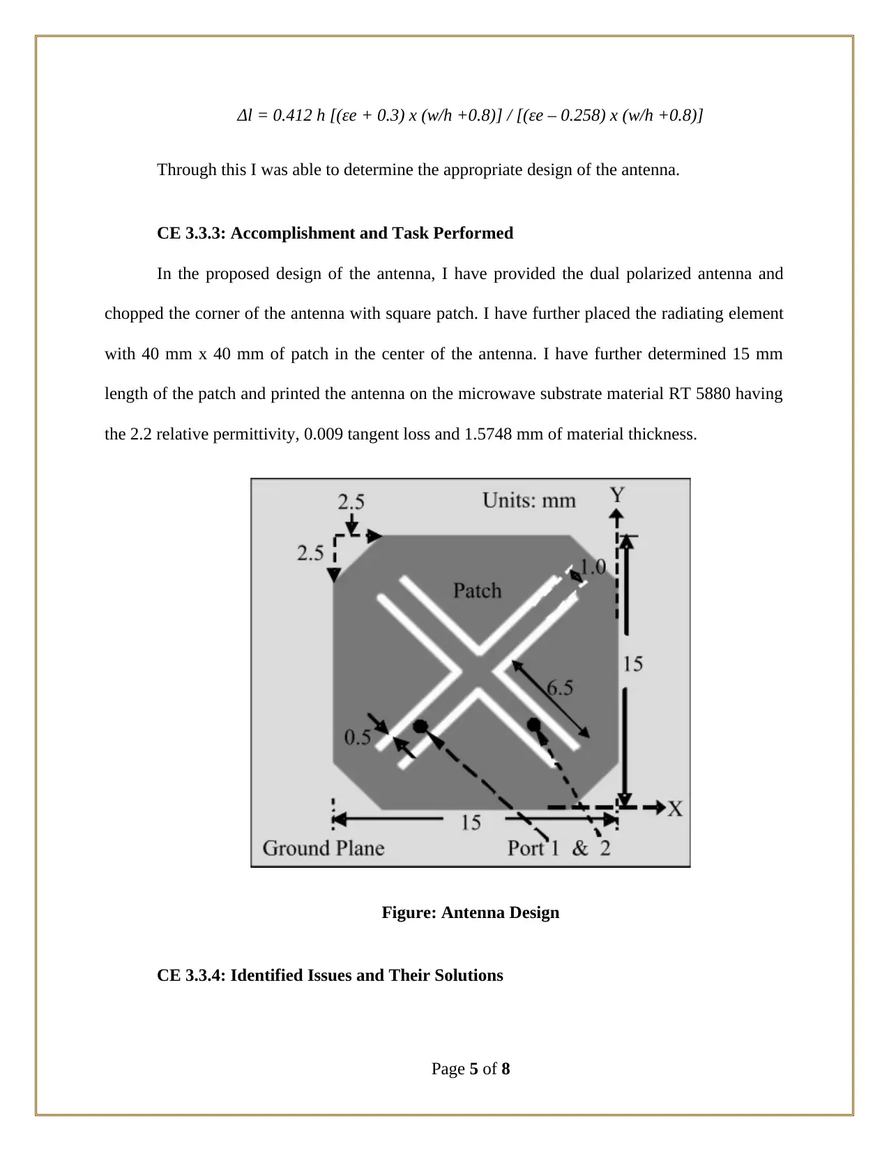
This report details the design and simulation of a dual polarized microstrip patch antenna, focusing on achieving high isolation and wide bandwidth. The project involved identifying limitations of existing antenna designs, determining factors impacting efficiency, and evaluating design characteristi...

Competency
Demonstration Report
(CDR)
Career Episode 3
Demonstration Report
(CDR)
Career Episode 3
Paraphrase This Document
Need a fresh take? Get an instant paraphrase of this document with our AI Paraphraser

CE 3.1: Project Introduction
Name of the Project : Design of Dual Polarized Microstrip Patch Antenna
Geographical Location : [Please Fill]
Project Duration : [Please Fill]
Organization : [Please Fill]
Position in the Project : Team Leader
CE 3.2. Project Background
CE 3.2.1: Characteristics of the Project
Two orthogonal modes are used in the dual microstrip polarized antenna for generating
the polarized electric field in both horizontal and vertical direction. The development of the dual
polarized antenna has provided to achieve both cross polarizations and co polarization through
the antenna. I have observed that the design of the dual polarized antenna helps in reducing the
impact of the multi path fading while improving the capacity of the channel. After reviewing
various literatures and past researches, I have observed that the coupling of the two ports at an
undesired level creates significant issue in the performance of antenna. The effect of coupling
significantly reduces the impedance bandwidth, antenna performance and radiation pattern
deterioration with each of the polarization observed. Therefore in this project, I have aimed at
achieving loss level of cross polarization, high isolation and wide bandwidth with the advanced
design of the dual polarization of microstrip patch antenna.
Page 1 of 8

CE 3.2.2: Objectives developed for project
Before imitating the practical work for antenna design I have observed that antennas
having narrow bands provide high isolation with greater return loss. Further, in wireless
applications, the antenna is designed with two layers that increased the cost and complexity of
fabrication. Therefore in this project, I have made my vital aim to propose an enhanced deign the
dual polarized antenna for improving the efficiency and bandwidth. Further, I have developed
the following objectives for highlighting the work activities and deliverables that needs to be
achieved for success of the project:
To identify the limitations of the existing dual polarized antenna;
To determine the factors impacting the efficiency of the dual polarized antenna;
To evaluate the design characteristic of the dual polarized antenna;
To design and integrate an effective design of the antenna;
To print the antenna and propose the required antenna geometry;
To simulate the antenna with commercial application;
CE 3.2.3: My area of work
I have studied and reviewed various papers, journals and books for identifying the
limitations and factors impacting the performance effectiveness of a dual polarized antenna. I
have further printed the antenna design on the required substrate and simulated the antenna
design in the commercial application. In this project I was successful in presenting a advanced
low cost design of dual polarized antenna.
CE 3.2.4: Project Group
Page 2 of 8
⊘ This is a preview!⊘
Do you want full access?
Subscribe today to unlock all pages.

Trusted by 1+ million students worldwide

Figure 1: Team Member Associated with the Project
CE 3.2.5: My responsibilities throughout the project
Apart from working on the technical side of the antenna, I had the major responsibility of
managing and leading the project group towards the timely completion. I have identified the
major activities and allocated the task within the group for promoting team work and early
completion.
CE 3.3: Distinctive Activity
CE 3.3.1: Comprehending the Theory of the project
In this particular project, I have proposed a design of antenna with dual polarized
microstrip patch. I have adopted the antenna while chopping the corner and bent the four slots in
the corner. I have significantly reduced the size of the polarized antenna while bent slots at four
symmetrical corners for archiving excellent radiation. I have aligned the four triangular
Page 3 of 8
Paraphrase This Document
Need a fresh take? Get an instant paraphrase of this document with our AI Paraphraser

symmetrical slots in parallel position in regards to the diagonal of the antenna in order to obtain
90o and 0o polarizations. In addition to that, I have used two units of probe feed for exciting the
polarizations. Furthermore, I have meandered the current path of the excited surface of the patch
for slot perturbation. In addition to that, I have reduced the size of the antenna for obtaining the
radiation of the dual patch antenna and reducing the complexity of the fabrication.
CE 3.3.2: Engineering Knowledge and Skills applied in the project
In the initial phase of the antenna design, I have worked for determining the side length
of the patch used in the antenna. For determining the length, I have used the following equation:
L = c / 2 fo (√εr) - 2Δ l
W = (c / 2 fo) x √ (εr + 1) / 2
In the above equation, I have used c for determining the light speed in vacuum, fo as the
frequency of the target, L as the patch length and for determining the width of the antenna, I have
used W. In addition to that, for determining the constant of dielectric I have utilized the
underlying equation for the antenna:
εr = ½ (εr + 1) + ½ (εr + 1) √ (1 + 10h/W)
In the illustrated above equation, I have used ε for showing the relative constant of
dielectric and for using the substrate thickness in the equation, I have used h. in addition to that, I
have make the physical dimension of the antenna much larger due to the presence of fringing
field. I have observed Δl increased in the length of the antenna due to the presence of fringing
field. Therefore for identifying the increased length of the antenna, I have formulated the
underlying formula:
Page 4 of 8

Δl = 0.412 h [(εe + 0.3) x (w/h +0.8)] / [(εe – 0.258) x (w/h +0.8)]
Through this I was able to determine the appropriate design of the antenna.
CE 3.3.3: Accomplishment and Task Performed
In the proposed design of the antenna, I have provided the dual polarized antenna and
chopped the corner of the antenna with square patch. I have further placed the radiating element
with 40 mm x 40 mm of patch in the center of the antenna. I have further determined 15 mm
length of the patch and printed the antenna on the microwave substrate material RT 5880 having
the 2.2 relative permittivity, 0.009 tangent loss and 1.5748 mm of material thickness.
Figure: Antenna Design
CE 3.3.4: Identified Issues and Their Solutions
Page 5 of 8
⊘ This is a preview!⊘
Do you want full access?
Subscribe today to unlock all pages.

Trusted by 1+ million students worldwide

Issue: I have associated myself with the evaluation and testing of the antenna bandwidth
for the designed polarized antenna. I have found that the initial design of the antenna was
operating at much higher bandwidth due to the size of the antenna developed. I have used the
radiating patch at the centre of the antenna for enhancing the efficiency. I have faced significant
issue when I have observed that the radiating patch was generating nodes that increased the
bandwidth of the antenna.
Solution: Furthermore, for enhancing the bandwidth, I have truncated the radiating patch
by 2.5 mm × 2.5 mm from each of the antenna corner. II have eliminated the same dimension
from each of the antenna corner for squaring the patch. I have provided 6.5 mm length and 0.5
mm width of the path along the diagonal of the antenna. Furthermore, I have kept 1mm space
between the two slots. Through the new specification of the antenna, I was able to achieve
impedance of 50 Ω from the proposed design of the dual polarized antenna.
CE 3.3.5: Plan for producing creative and innovative work
In order to provide innovation and creativeness in this project I have utilized the methods
that are commercially available for the antenna. Therefore, I have used full wave electromagnetic
simulator IE3D package for simulating the performance of the designed antenna for this project.
In the proposed antenna, I have obtained return loss is less than -10 dB between the range 12.71
to 11.76 GHz. Therefore from the analysis of the antenna with commercially available method, I
was able to provide accuracy in the antenna design while following standard procedure for both
design and simulation.
CE 3.3.6: Collaborative work
Page 6 of 8
Paraphrase This Document
Need a fresh take? Get an instant paraphrase of this document with our AI Paraphraser

I have worked alongside the team members in this project for ensuing the efficiency and
standard of the design being followed throughout the project. I have organized various team
meetings within months for discussing and highlighting any technical issue that we have come
across during both design and simulation process. Furthermore, I have encouraged the team
members for working in a collaborating way for distributing the work load equally among
different members.
CE 3.4: Project Review
CE 3.4.1: Project Overview
Through the successful completion of the antenna design, I was able to achieve the
coupling of the coaxial probe feed of the antenna. With the bend corner I was able to achieve the
applicable and width required for developing the design of the antenna. Therefore the proposed
antenna in this project can be easily implemented and fabricated on any materials due to the
proposed small thickness and size.
CE 3.4.2: My contribution to work
While working in this particular project, I have used my understanding and knowledge of
antenna design both as a team members and a team leader. As a team leader, I was successful in
providing the members with justifies and technical information regarding the design and
simulation of the antenna. While working as team members, I was successful in applying my
past experiences for providing an efficient and advanced design of dual polarized antenna.
Page 7 of 8
1 out of 8
Related Documents

Your All-in-One AI-Powered Toolkit for Academic Success.
+13062052269
info@desklib.com
Available 24*7 on WhatsApp / Email
Unlock your academic potential
© 2024 | Zucol Services PVT LTD | All rights reserved.