Competency Demonstration Report: Four Quadrant DC Motor Controller

Verified

Added on  2019/10/31

|10
|1660
|181
Report
AI Summary
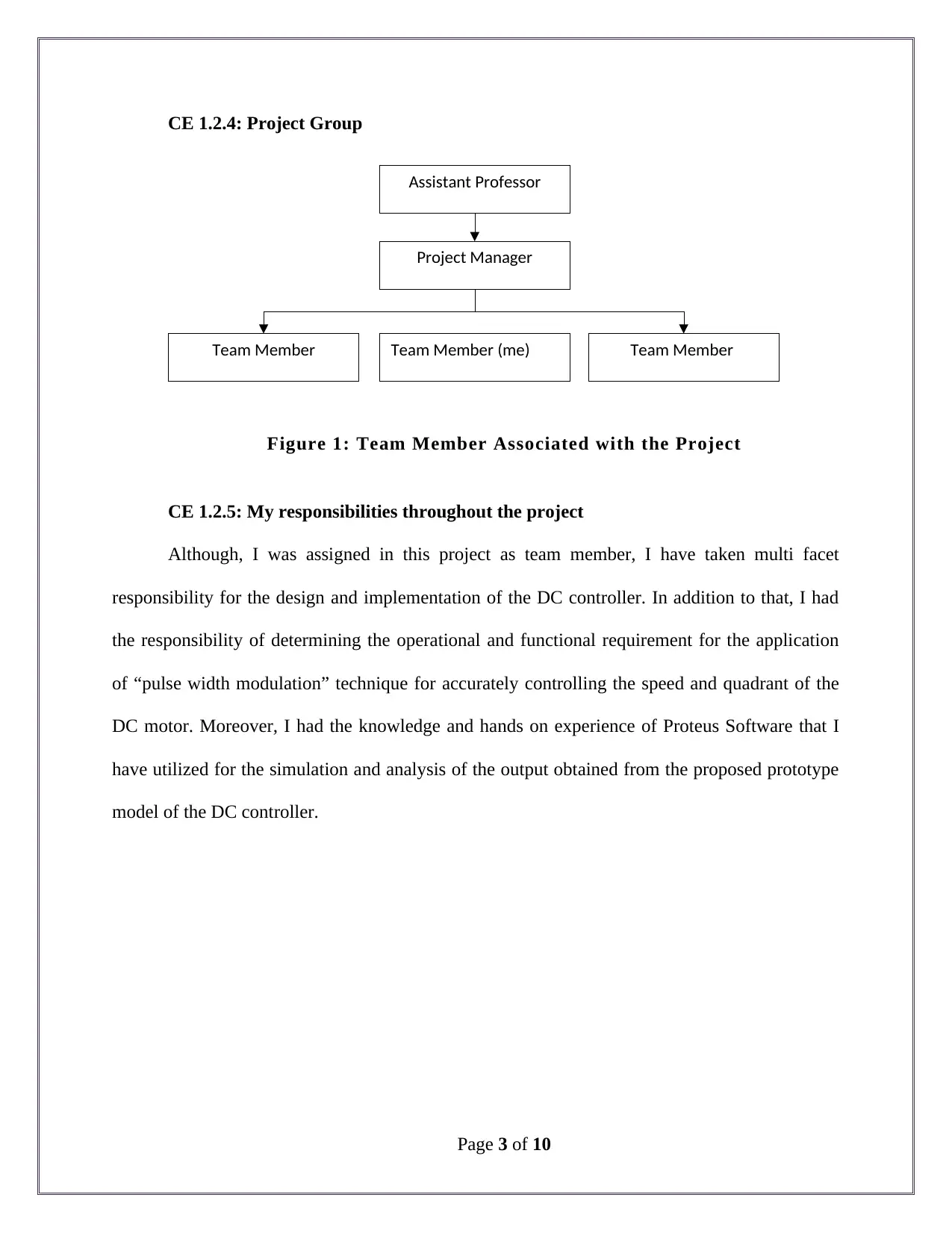
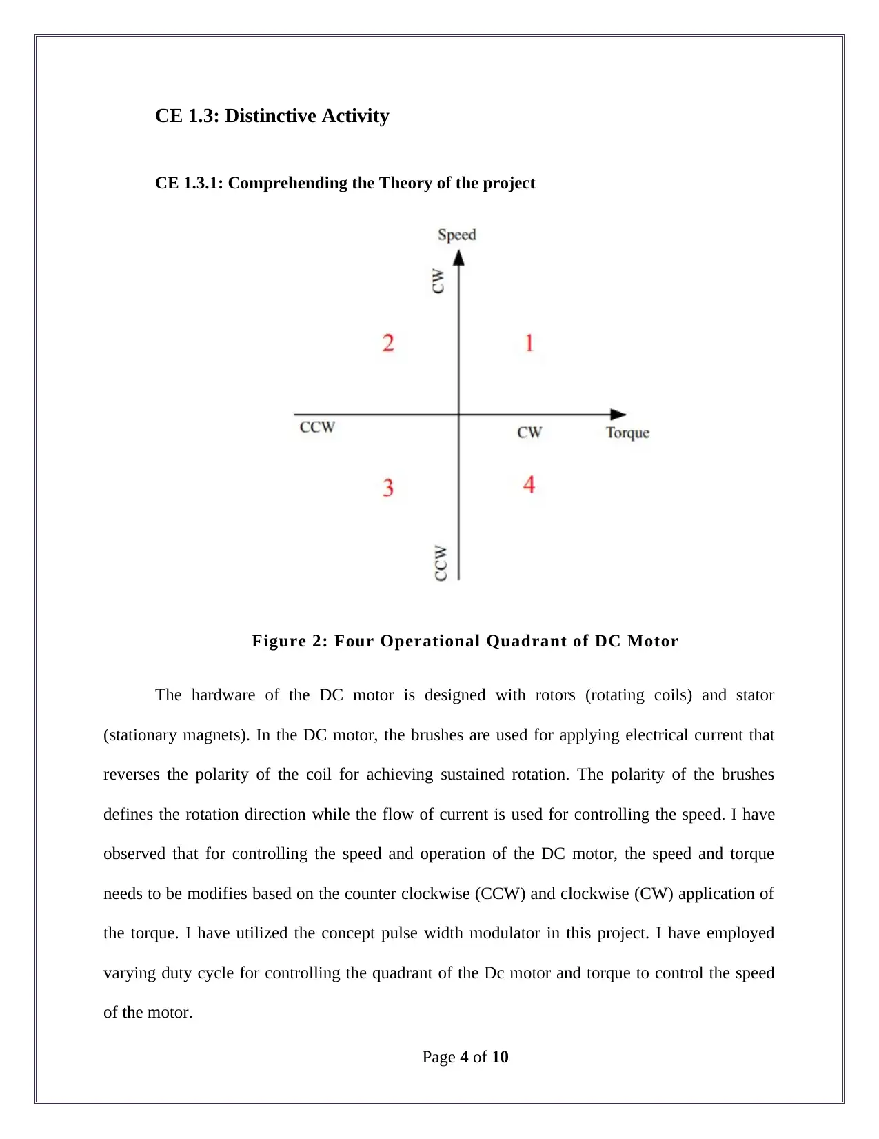
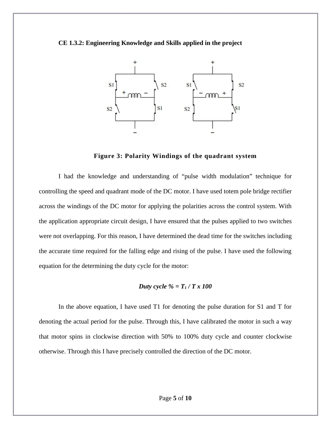
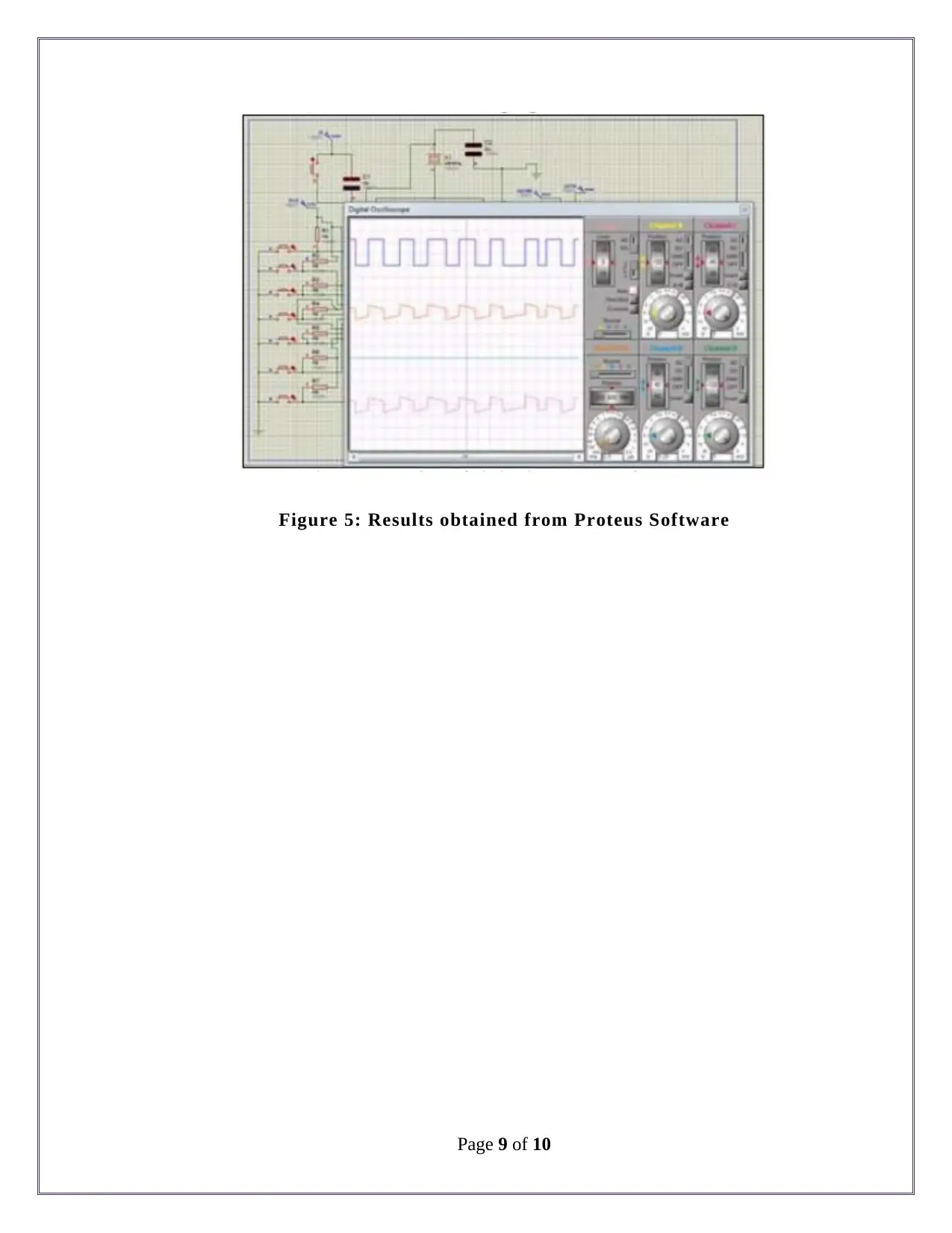
This document is a Competency Demonstration Report (CDR) detailing a student's project on the development of a four-quadrant DC motor controller. The report outlines the project's introduction, background, objectives, and the student's specific role as a team member. It describes the application of pulse width modulation (PWM) for controlling the speed and direction of the DC motor, including the use of VHDL for implementing a finite state machine (FSM). The student highlights the engineering knowledge and skills applied, the tasks performed, and the issues encountered and their solutions. The project involved designing a controller to manage both the speed and operational mode (clockwise, counterclockwise, forward brake, reverse brake) of a DC motor. The report includes block diagrams, circuit designs, and simulation results obtained using Proteus software. The student emphasizes the collaborative aspects of the project, decision-making processes, and the advantages of their approach compared to existing solutions, particularly in the use of Proteus for simulation and the control of both speed and rotational quadrant.
tabler-icon-diamond-filled.svg

Contribute Materials

Your contribution can guide someone’s learning journey. Share your documents today.
Document Page
Competency Demonstration Report (CDR)
Career Episode 1
tabler-icon-diamond-filled.svg

Secure Best Marks with AI Grader

Need help grading? Try our AI Grader for instant feedback on your assignments.
Document Page
CE 1.1: Project Introduction
Name of the Project : Development of Four Quadrant Dc Motor Controller
Geographical Location : [Please Fill]
Project Duration : [Please Fill]
Organization : [Please Fill]
Position in the Project : Team Member
CE 1.2: Project Background
CE 1.2.1: Characteristics of the Project
Controlling the speed of any machine is an essential part and aspect in the commercial
and industrial application of the DC motor. The Dc motor has the capability of operating in
various modes and speed. In industrial operations, the change in the operational mode and speed
of the motor in various scenarios are essential for the obtaining the optimum results and
continuing operations in the changing environment. Further, I have observed that in the market
there exists various commercial applications and operators for the sole control of the speed in the
industrial operations. Therefore, I undertook this project for the development and
implementation of a system for controlling and observing both the speed and operational mode
of the DC motor in industrial and commercial applications. In this project, I have focused on
using the concept and theory of pulse width modulation for the operational control of the DC
motor.
Page 1 of 10
Document Page
CE 1.2.2: Objectives developed for project
With my work in this project, I have aimed to design an appropriate controller for the
determining the operation and speed of DC motor. I have learnt that the DC motor has the
capability of operating in four major quadrants including reverse brake, forward brake, counter
clock wise and clockwise operational mode. I have proposed for controlling the operational
mode along with the control of the speed in each of the operational mode of the DC motor. The
objectives that I have developed for the timely completion of the speed controller of the DC
motor have been illustrated in the section below:
To understand the concept of PWM (Pulse Width Modulation) for controlling the
speed of the DC motors;
To evaluate and determine the operations of four- quadrant DC motor;
To determine the features and functional requirement of the digital logic of the
motor controller;
To utilize VHDL for implementing a finite state machine;
To simulate the operation of the developed controller with the application of FSM
(Finite State Machine) concept;
CE 1.2.3: My area of work
In this project, I have worked for developing the design and prototype model of the DC
motor controller. I have studied and determined the working principle of the DC motor and
identified the software and hardware requirement of the speed and quadrant controller. Apart
from that, I have worked for the design development and functional operation of the speed
controller.
Page 2 of 10
Document Page
Assistant Professor
Project Manager
Team Member (me)Team Member Team Member
CE 1.2.4: Project Group
Figure 1: Team Member Associated with the Project
CE 1.2.5: My responsibilities throughout the project
Although, I was assigned in this project as team member, I have taken multi facet
responsibility for the design and implementation of the DC controller. In addition to that, I had
the responsibility of determining the operational and functional requirement for the application
of “pulse width modulation” technique for accurately controlling the speed and quadrant of the
DC motor. Moreover, I had the knowledge and hands on experience of Proteus Software that I
have utilized for the simulation and analysis of the output obtained from the proposed prototype
model of the DC controller.
Page 3 of 10
tabler-icon-diamond-filled.svg

Secure Best Marks with AI Grader

Need help grading? Try our AI Grader for instant feedback on your assignments.
Document Page
CE 1.3: Distinctive Activity
CE 1.3.1: Comprehending the Theory of the project
Figure 2: Four Operational Quadrant of DC Motor
The hardware of the DC motor is designed with rotors (rotating coils) and stator
(stationary magnets). In the DC motor, the brushes are used for applying electrical current that
reverses the polarity of the coil for achieving sustained rotation. The polarity of the brushes
defines the rotation direction while the flow of current is used for controlling the speed. I have
observed that for controlling the speed and operation of the DC motor, the speed and torque
needs to be modifies based on the counter clockwise (CCW) and clockwise (CW) application of
the torque. I have utilized the concept pulse width modulator in this project. I have employed
varying duty cycle for controlling the quadrant of the Dc motor and torque to control the speed
of the motor.
Page 4 of 10
Document Page
CE 1.3.2: Engineering Knowledge and Skills applied in the project
Figure 3: Polarity Windings of the quadrant system
I had the knowledge and understanding of “pulse width modulation” technique for
controlling the speed and quadrant mode of the DC motor. I have used totem pole bridge rectifier
across the windings of the DC motor for applying the polarities across the control system. With
the application appropriate circuit design, I have ensured that the pulses applied to two switches
were not overlapping. For this reason, I have determined the dead time for the switches including
the accurate time required for the falling edge and rising of the pulse. I have used the following
equation for the determining the duty cycle for the motor:
Duty cycle % = T1 / T x 100
In the above equation, I have used T1 for denoting the pulse duration for S1 and T for
denoting the actual period for the pulse. Through this, I have calibrated the motor in such a way
that motor spins in clockwise direction with 50% to 100% duty cycle and counter clockwise
otherwise. Through this I have precisely controlled the direction of the DC motor.
Page 5 of 10
Document Page
CE 1.3.3: Accomplishment and Task Performed
I have broken the design of the DC controller in several modules for simplifying the
design of the circuit. I have further designed the appropriate block diagram defining the
transformer, voltage regulator, bridge rectifier, motor driver, switch array and required DC
motor. In addition to that, I have attached the electronic sensors with the tote, pole bridge
rectifier.
Figure 4: Block Diagram for the DC controller
CE 1.3.4: Identified Issues and Their Solutions
Issue: In this project, I have focused on selecting the rotation direction and steady state
velocity of the DC motor. For this process, I have focused on supplying accurate pulses to the
duty cycle. I have worked in the designing phase with the gradual increase of current swings
Page 6 of 10
tabler-icon-diamond-filled.svg

Paraphrase This Document

Need a fresh take? Get an instant paraphrase of this document with our AI Paraphraser
Document Page
along the motor windings. But, I have faced significant issue during the design of the motor
controller when I was unable to apply the appropriate torque. This has resulted in the sudden
decelerate and accelerate of the motor.
Solution: For this process, I have implemented sensors along the DC motor for
monitoring the winding current values and speed of the operating DC motor. Through this, I was
accurately determined the direction and speed of the DC motor. Apart from that, I have used the
input obtained from the sensors for gradually increasing and decreasing the duty cycle through
pulse chain.
CE 1.3.5: Plan for producing creative and innovative work
I have utilized the theory and concept of FSM (Finite State Machine) for designating the
required DC motor controller. In addition to that, I have attached 0 to 7 counter and divide by 8
counter with the FSM unit. I have used the FSM unit for generating the input for the two
switches with the generation of desired waveform. I have utilized divide by 8 counter for
controlling the duty cycle and waveform period. In this project, I have mentioned and determined
various specifications for the DC motor controller. I have further programmed 50% duty cycle as
the default state for the controller.
CE 1.3.6: Collaborative work
I have worked in this project with the collaboration and team work of three members
associated with the completion and development of the DC controller’s prototype model. I have
initiated the collaborative work with brainstorming session and regular meetings. With regular
meeting sessions I was able to ensure proper flow of information among the team members.
Page 7 of 10
Document Page
CE 1.4: Project Review
CE 1.4.1: Decision Making Process
In the brainstorming session that I have participated during the implementation of the DC
controller, I have sub divided the project into two major phase. In the first phase, I was involved
with the hardware implementation of the DC controller. While in the second phase, I was
involved in the simulation of the results. I have been successful in determining the hardware and
software requirements while developing the prototype model of the DC controller.
CE 1.4.2: Comparatively Better In This Project Among Other Similar Projects
Various DC Controllers available in the market are capable of detecting and controlling
the speed of the DC motor for the practical and industrial application. In this project, I have
achieved the control and monitoring of the DC motor with respect to speed and rotational
quadrant of the motor. In addition to that, I have Proteus Software for simulating the results
based on the operational quadrant. Other existing studies use CRO for simulating the results, but
I have utilized Proteus Software for obtaining better results.
Page 8 of 10
Document Page
Figure 5: Results obtained from Proteus Software
Page 9 of 10
chevron_up_icon
1 out of 10
circle_padding
hide_on_mobile
zoom_out_icon
logo.png

Your All-in-One AI-Powered Toolkit for Academic Success.

Available 24*7 on WhatsApp / Email

[object Object]