Evaluating Composite Materials for Railway Track Construction

Verified

Added on  2023/03/29

|9
|1475
|136
Report
AI Summary
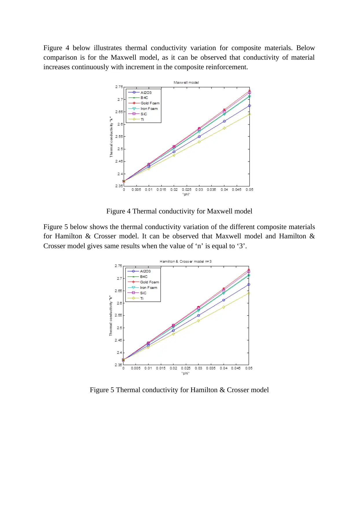
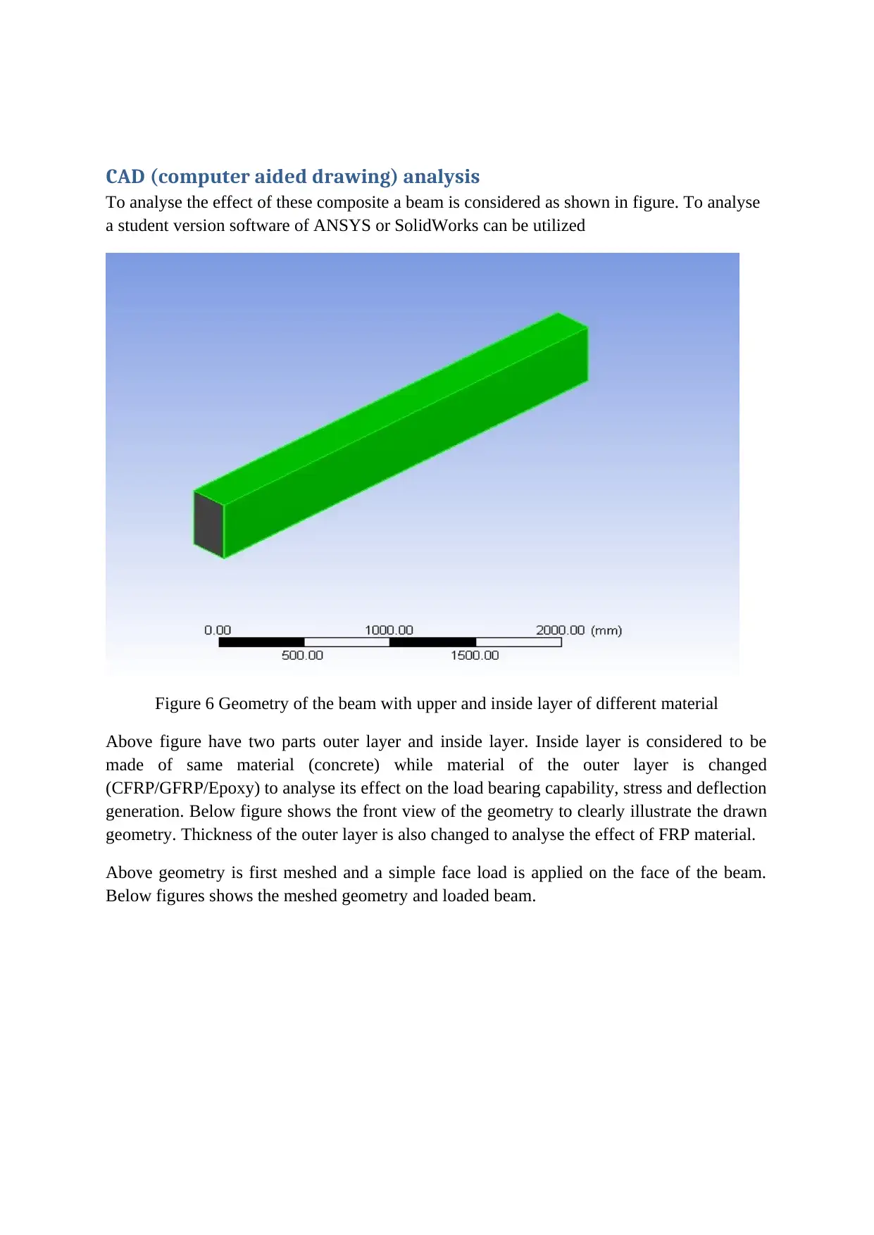
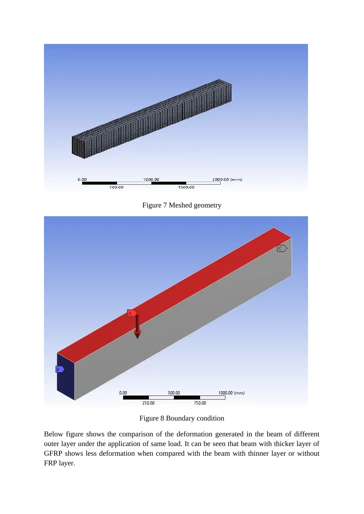
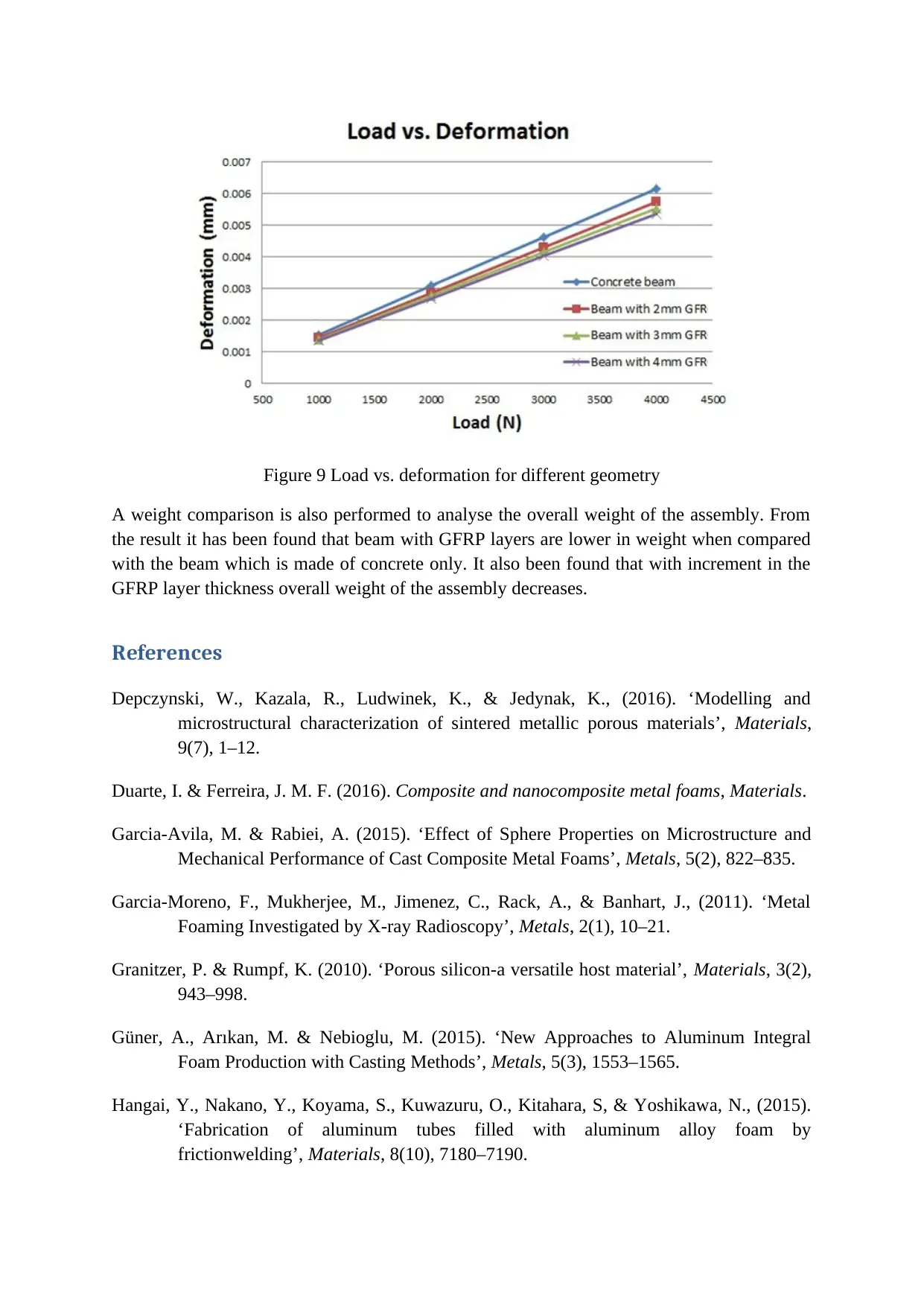
This report explores the application of composite materials in railway track construction as a replacement for conventional materials. It discusses various composite materials such as asphalt, carbon epoxy, glass epoxy, and fiber epoxy, highlighting their high strength and load-bearing capabilities. The report delves into the properties of concrete, epoxy, and nanocomposites, including metal matrix composites (MMCs), and their advantages over traditional materials. Mathematical formulas for calculating mechanical properties like compressive strength, tensile strength, hardness, shear modulus, and bulk modulus are presented. The thermal properties of these composites are also examined, with equations for calculating thermal conductivity based on density and reinforcement. Models such as the Maxwell model, Yu & Choi model, and Hamilton & Crosser model are discussed. The report includes a CAD analysis of a beam with different outer layer materials (CFRP/GFRP/Epoxy) to assess load-bearing capability, stress, and deflection, along with a weight comparison. The results indicate that beams with GFRP layers exhibit less deformation and lower weight, demonstrating the benefits of using composite materials in railway track design. This report is available on Desklib, where students can find a wealth of similar assignments and study resources.
tabler-icon-diamond-filled.svg

Contribute Materials

Your contribution can guide someone’s learning journey. Share your documents today.
Document Page
Material
Conventional materials (combination of elastic) used to manufacture the railway track are
being replaced by different composite materials like asphalt, carbon epoxy, glass epoxy, fiber
epoxy etc. Railway track made from these materials are called as ballastless track. These
composite materials possess high strength and load bearing capability compared to
conventional materials. These composite materials sometimes are also called as metal matrix
composites (MMCs). MMCs are the combination of the base material and reinforced small
size particles. These small size particles are nothing but the metal in powder form. Sometimes
concrete with aggregates is also used to make these ballastless.
Concrete
Concrete is generally made from Portland cement, aggregates, admixtures etc. Mostly utilized
cement is Portland cement which is made of silica, iron oxide, lime and alumina. Proportion
of these contents should be in accurate proportion otherwise it may result in disintegration of
cement. Some natural aggregates which come in concrete are basalt, granite etc. These
aggregates should be clean, inert & durable and should not have silica as availability of silica
may result in disintegration as stated above.
Epoxy
Epoxy is the end products of epoxy resins, these epoxy resins are also called as monomers or
prepolymers. Epoxy can be classified in various categories depending upon the type of
composite or material reinforced. They can be classified as carbon epoxy, glass epoxy fiber
epoxy etc. They can also be named as GFRP (glass fiber reinforced polymer), CFRP (carbon
fiber reinforced polymer) etc.
Nanocomposites
Some other nanocomposites can also be utilized to make ballastless track. These
nanocomposites are the powder of solid metal reinforced into the base material which also is
a metal. These nanocomposites can be aluminium oxide (Al2O3), silicon carbide (SiC), boron
carbide (B4C) etc. Advantages of these nanocomposites are that they are lighter in weight
compared with conventional materials like steel or iron. These nanocomposites have higher
mechanical, thermal and physical properties when compared with conventional materials
(Hangai, 2015; Jinnapat and Kennedy, 2011; Koizumi et al, 2011; Turan et al, 2012).
Mechanical properties of the materials
Table below shows some mathematical formulas to calculate some important properties like,
compressive strength, tensile strength, hardness, shear modulus and bulk modulus etc. These
all are the mechanical properties of the material. In the below mathematical formulas
subscript ‘s’ is for the base material while composite or reinforced material properties are
without any subscript.
tabler-icon-diamond-filled.svg

Secure Best Marks with AI Grader

Need help grading? Try our AI Grader for instant feedback on your assignments.
Document Page
Properties Open-cell type foam
Compressive strength σ c= ( 0.11.0 ) σ c ,s ( ρ
ρs ) 3
2
Tensile strength σ t ( 1.11.4 ) σ c
Bulk Modulus K 1.1 E
Shear Modulus G 3
8 E
Hardness H=σc (1+2 ρ
ρs )
Thermal properties of materials
Similar to mechanical properties thermal properties of these composite can also be calculated
using mathematical equation. They can be measured in two ways. In one way it can be
measured using density of the base material while in second way it can be measured for the
amount of composite reinforced into the base material using mathematical equations given by
well-known researchers (Garcia-Moreno et al, 2011; Granitzer and Rumpf, 2010; Güner,
Arıkan and Nebioglu, 2015)
In terms of density
In terms of density thermal properties can be using the mathematical equation given below
as,
k =k s ( ρ
ρs )q
In terms of reinforcement
There are wide verities of models given by researchers around the globe to calculate the
thermal properties of composite, but some well-known mathematical formulas are Hamilton
& Crosser model, Yu & Choi model, Maxwell model etc (Depczynski et al, 2016; Duarte and
Ferreira, 2016; Garcia-Avila and Rabiei, 2011; Kosti, 2014; Kosti and Malvi, 2018)
Maxwell model
k N =
[ ( k p +2 k s ) +2 ϕ ( k pk s )
( k p +2 ks ) ϕ ( k pks ) ] ks
Yu & Choi model
k N =
[ ( ke +2 ks ) +2 ϕ ( k eks ) ( 1+ β ) 3
( ke+2 k s ) ϕ ( kek s ) ( 1+ β ) 3 ] k s
Document Page
Hamilton & Crosser model
k N =
[ k p + ( n1 ) ks + ( n1 ) ( k pks ) ϕ
k p + ( n1 ) k s ( k p k s ) ϕ ] ks
Where:
k Thermal conductivity
ϕ Amount of composite reinforced
p and s Composite and solid metal
β It is the thickness to radius ratio of composite
n Shape factor
Composite K (W/m-K) Cp (J/kg-K) ρ (kg/m3)
B4C 42 1288 2550
Al2O3 36 773 3880
SiC 100 1300 3200
Analyse of materials
These composite materials can deviates the thermal properties. Figure 1 shows the variation
of compressive strength for some composite materials.
Figure 1 Compressive strength for different composite materials.
Document Page
Figure 2 shows the variation of hardness for some composite materials.
Figure 2 Hardness for different composite materials.
Figure 3 below shows the density based thermal conductivity variation for some composite
materials
Figure 3 Thermal conductivity for density based method
tabler-icon-diamond-filled.svg

Secure Best Marks with AI Grader

Need help grading? Try our AI Grader for instant feedback on your assignments.
Document Page
Figure 4 below illustrates thermal conductivity variation for composite materials. Below
comparison is for the Maxwell model, as it can be observed that conductivity of material
increases continuously with increment in the composite reinforcement.
Figure 4 Thermal conductivity for Maxwell model
Figure 5 below shows the thermal conductivity variation of the different composite materials
for Hamilton & Crosser model. It can be observed that Maxwell model and Hamilton &
Crosser model gives same results when the value of ‘n’ is equal to ‘3’.
Figure 5 Thermal conductivity for Hamilton & Crosser model
Document Page
CAD (computer aided drawing) analysis
To analyse the effect of these composite a beam is considered as shown in figure. To analyse
a student version software of ANSYS or SolidWorks can be utilized
Figure 6 Geometry of the beam with upper and inside layer of different material
Above figure have two parts outer layer and inside layer. Inside layer is considered to be
made of same material (concrete) while material of the outer layer is changed
(CFRP/GFRP/Epoxy) to analyse its effect on the load bearing capability, stress and deflection
generation. Below figure shows the front view of the geometry to clearly illustrate the drawn
geometry. Thickness of the outer layer is also changed to analyse the effect of FRP material.
Above geometry is first meshed and a simple face load is applied on the face of the beam.
Below figures shows the meshed geometry and loaded beam.
Document Page
Figure 7 Meshed geometry
Figure 8 Boundary condition
Below figure shows the comparison of the deformation generated in the beam of different
outer layer under the application of same load. It can be seen that beam with thicker layer of
GFRP shows less deformation when compared with the beam with thinner layer or without
FRP layer.
tabler-icon-diamond-filled.svg

Paraphrase This Document

Need a fresh take? Get an instant paraphrase of this document with our AI Paraphraser
Document Page
Figure 9 Load vs. deformation for different geometry
A weight comparison is also performed to analyse the overall weight of the assembly. From
the result it has been found that beam with GFRP layers are lower in weight when compared
with the beam which is made of concrete only. It also been found that with increment in the
GFRP layer thickness overall weight of the assembly decreases.
References
Depczynski, W., Kazala, R., Ludwinek, K., & Jedynak, K., (2016). ‘Modelling and
microstructural characterization of sintered metallic porous materials’, Materials,
9(7), 1–12.
Duarte, I. & Ferreira, J. M. F. (2016). Composite and nanocomposite metal foams, Materials.
Garcia-Avila, M. & Rabiei, A. (2015). ‘Effect of Sphere Properties on Microstructure and
Mechanical Performance of Cast Composite Metal Foams’, Metals, 5(2), 822–835.
Garcia-Moreno, F., Mukherjee, M., Jimenez, C., Rack, A., & Banhart, J., (2011). ‘Metal
Foaming Investigated by X-ray Radioscopy’, Metals, 2(1), 10–21.
Granitzer, P. & Rumpf, K. (2010). ‘Porous silicon-a versatile host material’, Materials, 3(2),
943–998.
Güner, A., Arıkan, M. & Nebioglu, M. (2015). ‘New Approaches to Aluminum Integral
Foam Production with Casting Methods’, Metals, 5(3), 1553–1565.
Hangai, Y., Nakano, Y., Koyama, S., Kuwazuru, O., Kitahara, S, & Yoshikawa, N., (2015).
‘Fabrication of aluminum tubes filled with aluminum alloy foam by
frictionwelding’, Materials, 8(10), 7180–7190.
Document Page
Jinnapat, A. & Kennedy, A. (2011). ‘The Manufacture and Characterisation of Aluminium
Foams Made by Investment Casting Using Dissolvable Spherical Sodium Chloride
Bead Preforms’, Metals, 1(1), 49–64.
Koizumi, T., Kido, K., Kita, K., Mikado, K., Gnyloskurenko, S., & Nakamura, T., (2011).
‘Method of Preventing Shrinkage of Aluminum Foam Using Carbonates’, Metals,
2(4), 1–9.
Kosti, S, (2014). ‘Numerical Study of heat flux boundary in nanofluid-filled cavity’,
Nanomaterials and Energy, 3(6), 193-205
Kosti, S., & Malvi, C. S., (2018). ‘Cumulative influence of nanoparticles on MMCs’ time–
temperature history curve’, Nanomaterials and Energy, 7(1), 1-10.
Turan, O., Poole, R.J., & Chakraborty, N., (2012), Influences of Boundary Conditions on
Laminar Natural Convection in Rectangular Enclosures with Differentially Heated
Side Walls, International Journal of Heat and Fluid Flow, 33, 131-146.
chevron_up_icon
1 out of 9
circle_padding
hide_on_mobile
zoom_out_icon
logo.png

Your All-in-One AI-Powered Toolkit for Academic Success.

Available 24*7 on WhatsApp / Email

[object Object]