Finite Element Analysis of Composite Plates: ANSYS Comparison
VerifiedAdded on 2022/09/17
|14
|1991
|25
Report
AI Summary
This report presents a comprehensive finite element analysis of composite plates using ANSYS software. The study investigates three numerical methods: ANSYS 3D (RVE based), ANSYS ACP, and Structure Genome, comparing their accuracy and computational efficiency. The report includes an introduction to composite materials, discussing their advantages, manufacturing, and the challenges of modeling their anisotropic behavior. It delves into the mechanics of composite modeling, explaining RVEs and equivalent plate theories. Numerical examples demonstrate the application of ANSYS for composite analysis, with comparisons of stress and deformation results obtained from the three methods. The report concludes that the Structure Genome approach offers comparable accuracy with significantly reduced computation time. The report includes tables and figures to support the analysis and provides relevant references.
Finite Element Analysis of Composite plates using
ANSYS
<Student Name>
<Student Number>
Assignment Report
Supervisor: <XXX>
DEPARTMENT NAME
University NAME
<Month Year>
ANSYS
<Student Name>
<Student Number>
Assignment Report
Supervisor: <XXX>
DEPARTMENT NAME
University NAME
<Month Year>
Paraphrase This Document
Need a fresh take? Get an instant paraphrase of this document with our AI Paraphraser
ABSTRACT
Laminate composites are very widely used in industry now specifically in aerospace application.
Due to their high strength to weight ratio, laminated composites are preferred to manufacture
component since it is very lightweight. Designing and analysing performance of such
components is very difficult by analytical methods hence numerical (finite element based)
methods are used for laminated composites. In the current report, 3 different numerical methods
namely ANSYS 3D (RVE based), ANSYS ACP and Structure genome are explained and
compared for their accuracy and computation time. It was concluded based on literature data that
structure genome based methods are equally accurate by 60-80% less computationally expensive.
i
TABLE OF CONTENTS
ABSTRACT......................................................................................................................................i
TABLE OF CONTENTS.................................................................................................................ii
CHAPTER I: INTRODUCTION.....................................................................................................1
CHAPTER II: MODELING OF COMPOSITES............................................................................2
Mechanics of Composite modeling..............................................................................................2
Disadvantages..........................................................................................................................3
Equivalent plate theories used for composite analysis.................................................................3
First order Shear deformation theory.......................................................................................4
Constitutive laws used for Composite modelling....................................................................4
CHAPTER III: NUMERICAL EXAMPLES..................................................................................6
CHAPTER IV: CONCLUSION....................................................................................................10
References......................................................................................................................................11
ii
⊘ This is a preview!⊘
Do you want full access?
Subscribe today to unlock all pages.
Trusted by 1+ million students worldwide
CHAPTER I: INTRODUCTION
Composites are very commonly used across many industries where strength to weight ratio
requirements are high but cost is not a significant design factor. Composites are characterized by
very high stiffness due to fibre such as carbon or glass which are typically used to manufacture
them. Composites are usually manufactured layer-by-layer using epoxy. A typical woven pattern
of chosen fiber (natural, glass, carbon etc.) is taken in long strands form with a chosen weave
such as twill etc. This makes a continuous cloth of the woven fibre with micro thickness. A
specific characteristic of fibres is their anisotropy i.e. different strength along the fibre and cross-
fibre direction. When a cloth is fabricated, it also has a preferred longitudinal direction or fibre
direction and lateral or cross-fibre direction. Composites are manufactured by taking fibre
clothes, dipping them into epoxy resins and curing them to make a single layer. If multiple layers
are stacked and glued one over the other then it results in a composite structure of a particular
type.
Directional performance of the composite will depend on the angle which are taken in the
stacking of layers to make the laminate. Usually, it symmetric pattern of layers are stacks with
different angles so that laminate exhibit uniform properties in – plane. Out of plane properties of
laminate composites are always weaker because strengthening fibers don’t contribute in out of
plane direction and it is also glue strength. Hence it is necessary to align the laminated
composites in a preferred loading direction so as to take benefit of directional strength [1].
Capturing the 3D anisotropic behaviour of composite takes different approaches compared to
metals which are isotropic. Many commercial finite element tools now offer preparing a custom
laminate and analyse for applied loading. Although making a 3D model consisting of micro-level
details could be very time consuming and computationally expensive. Hence researchers have
derived several multi-scale theories which model a laminate composite as a single layer and these
are usually called ‘Equivalent Single Layer (ESL)’ theories. Other widely used theory for
analysis of composites in ‘First order shear deformation theory’ which is used by ANSYS for
modelling of composites as a layered structure. Commercial software package ANSYS uses
SHELL181 as the 4-noded quad element for modelling a composite and non-linear by
introducing a mid-side node, SHELL281 is used as a 8-noded quad element [4].
Further details of relevant analysis methods and examples are explored in current study.
1
Paraphrase This Document
Need a fresh take? Get an instant paraphrase of this document with our AI Paraphraser
CHAPTER II: MODELING OF COMPOSITES
In this chapter, Mechanics of composite modelling and a few widely used theories are discussed.
Mechanics of Composite modeling
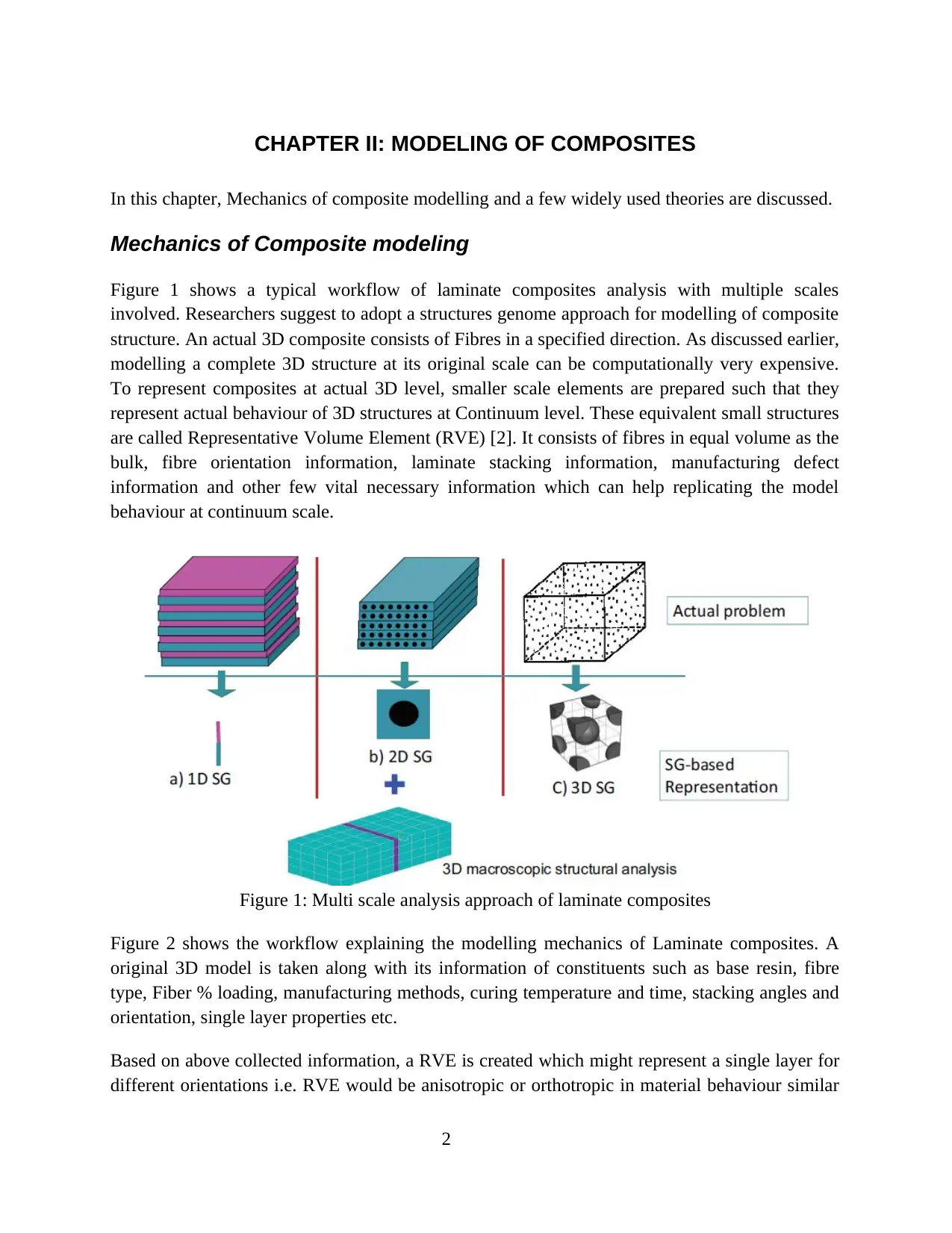
Figure 1 shows a typical workflow of laminate composites analysis with multiple scales
involved. Researchers suggest to adopt a structures genome approach for modelling of composite
structure. An actual 3D composite consists of Fibres in a specified direction. As discussed earlier,
modelling a complete 3D structure at its original scale can be computationally very expensive.
To represent composites at actual 3D level, smaller scale elements are prepared such that they
represent actual behaviour of 3D structures at Continuum level. These equivalent small structures
are called Representative Volume Element (RVE) [2]. It consists of fibres in equal volume as the
bulk, fibre orientation information, laminate stacking information, manufacturing defect
information and other few vital necessary information which can help replicating the model
behaviour at continuum scale.
Figure 1: Multi scale analysis approach of laminate composites
Figure 2 shows the workflow explaining the modelling mechanics of Laminate composites. A
original 3D model is taken along with its information of constituents such as base resin, fibre
type, Fiber % loading, manufacturing methods, curing temperature and time, stacking angles and
orientation, single layer properties etc.
Based on above collected information, a RVE is created which might represent a single layer for
different orientations i.e. RVE would be anisotropic or orthotropic in material behaviour similar
2
In this chapter, Mechanics of composite modelling and a few widely used theories are discussed.
Mechanics of Composite modeling
Figure 1 shows a typical workflow of laminate composites analysis with multiple scales
involved. Researchers suggest to adopt a structures genome approach for modelling of composite
structure. An actual 3D composite consists of Fibres in a specified direction. As discussed earlier,
modelling a complete 3D structure at its original scale can be computationally very expensive.
To represent composites at actual 3D level, smaller scale elements are prepared such that they
represent actual behaviour of 3D structures at Continuum level. These equivalent small structures
are called Representative Volume Element (RVE) [2]. It consists of fibres in equal volume as the
bulk, fibre orientation information, laminate stacking information, manufacturing defect
information and other few vital necessary information which can help replicating the model
behaviour at continuum scale.
Figure 1: Multi scale analysis approach of laminate composites
Figure 2 shows the workflow explaining the modelling mechanics of Laminate composites. A
original 3D model is taken along with its information of constituents such as base resin, fibre
type, Fiber % loading, manufacturing methods, curing temperature and time, stacking angles and
orientation, single layer properties etc.
Based on above collected information, a RVE is created which might represent a single layer for
different orientations i.e. RVE would be anisotropic or orthotropic in material behaviour similar
2
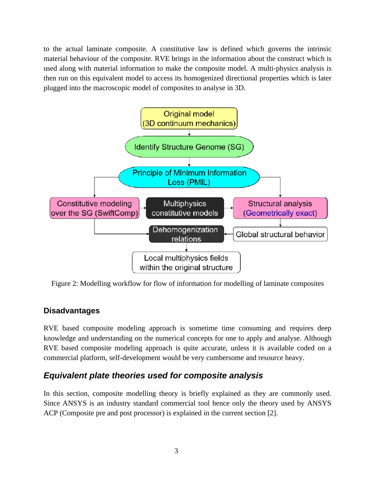
to the actual laminate composite. A constitutive law is defined which governs the intrinsic
material behaviour of the composite. RVE brings in the information about the construct which is
used along with material information to make the composite model. A multi-physics analysis is
then run on this equivalent model to access its homogenized directional properties which is later
plugged into the macroscopic model of composites to analyse in 3D.
Figure 2: Modelling workflow for flow of information for modelling of laminate composites
Disadvantages
RVE based composite modeling approach is sometime time consuming and requires deep
knowledge and understanding on the numerical concepts for one to apply and analyse. Although
RVE based composite modeling approach is quite accurate, unless it is available coded on a
commercial platform, self-development would be very cumbersome and resource heavy.
Equivalent plate theories used for composite analysis
In this section, composite modelling theory is briefly explained as they are commonly used.
Since ANSYS is an industry standard commercial tool hence only the theory used by ANSYS
ACP (Composite pre and post processor) is explained in the current section [2].
3
⊘ This is a preview!⊘
Do you want full access?
Subscribe today to unlock all pages.
Trusted by 1+ million students worldwide
First order Shear deformation theory
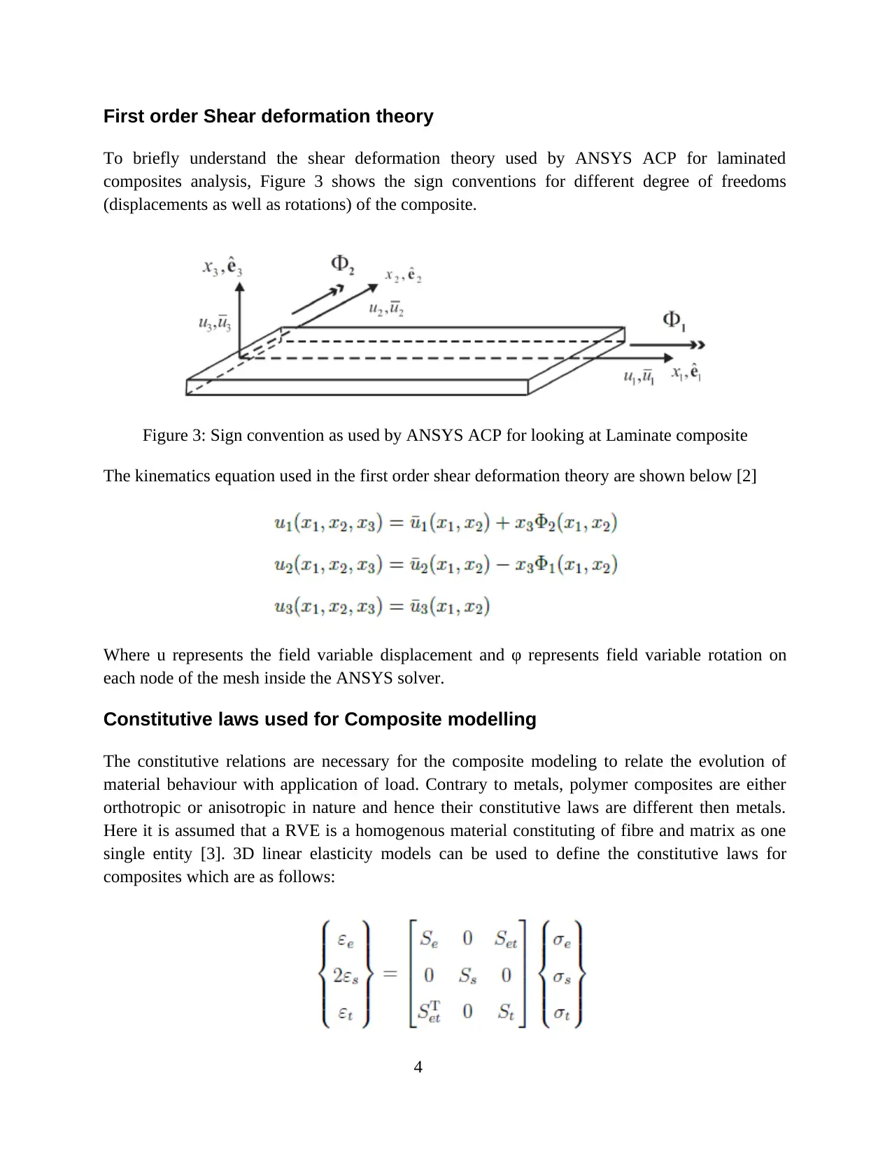
To briefly understand the shear deformation theory used by ANSYS ACP for laminated
composites analysis, Figure 3 shows the sign conventions for different degree of freedoms
(displacements as well as rotations) of the composite.
Figure 3: Sign convention as used by ANSYS ACP for looking at Laminate composite
The kinematics equation used in the first order shear deformation theory are shown below [2]
Where u represents the field variable displacement and φ represents field variable rotation on
each node of the mesh inside the ANSYS solver.
Constitutive laws used for Composite modelling
The constitutive relations are necessary for the composite modeling to relate the evolution of
material behaviour with application of load. Contrary to metals, polymer composites are either
orthotropic or anisotropic in nature and hence their constitutive laws are different then metals.
Here it is assumed that a RVE is a homogenous material constituting of fibre and matrix as one
single entity [3]. 3D linear elasticity models can be used to define the constitutive laws for
composites which are as follows:
4
Paraphrase This Document
Need a fresh take? Get an instant paraphrase of this document with our AI Paraphraser
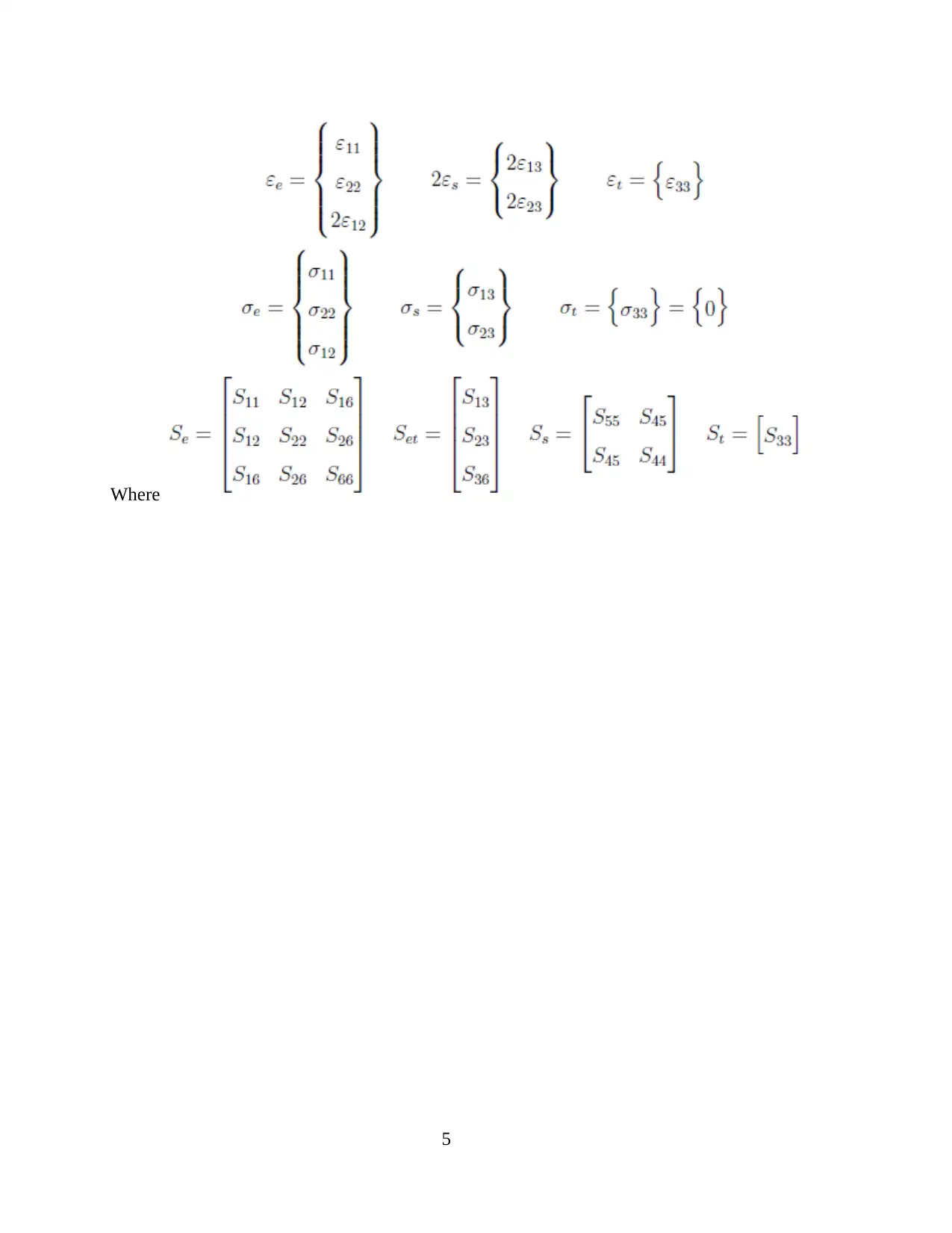
Where
5
5
CHAPTER III: NUMERICAL EXAMPLES
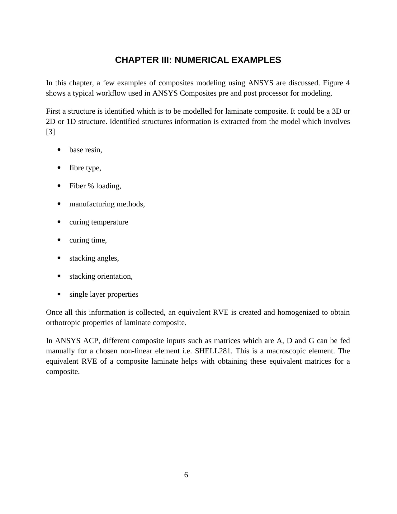
In this chapter, a few examples of composites modeling using ANSYS are discussed. Figure 4
shows a typical workflow used in ANSYS Composites pre and post processor for modeling.
First a structure is identified which is to be modelled for laminate composite. It could be a 3D or
2D or 1D structure. Identified structures information is extracted from the model which involves
[3]
base resin,
fibre type,
Fiber % loading,
manufacturing methods,
curing temperature
curing time,
stacking angles,
stacking orientation,
single layer properties
Once all this information is collected, an equivalent RVE is created and homogenized to obtain
orthotropic properties of laminate composite.
In ANSYS ACP, different composite inputs such as matrices which are A, D and G can be fed
manually for a chosen non-linear element i.e. SHELL281. This is a macroscopic element. The
equivalent RVE of a composite laminate helps with obtaining these equivalent matrices for a
composite.
6
⊘ This is a preview!⊘
Do you want full access?
Subscribe today to unlock all pages.
Trusted by 1+ million students worldwide
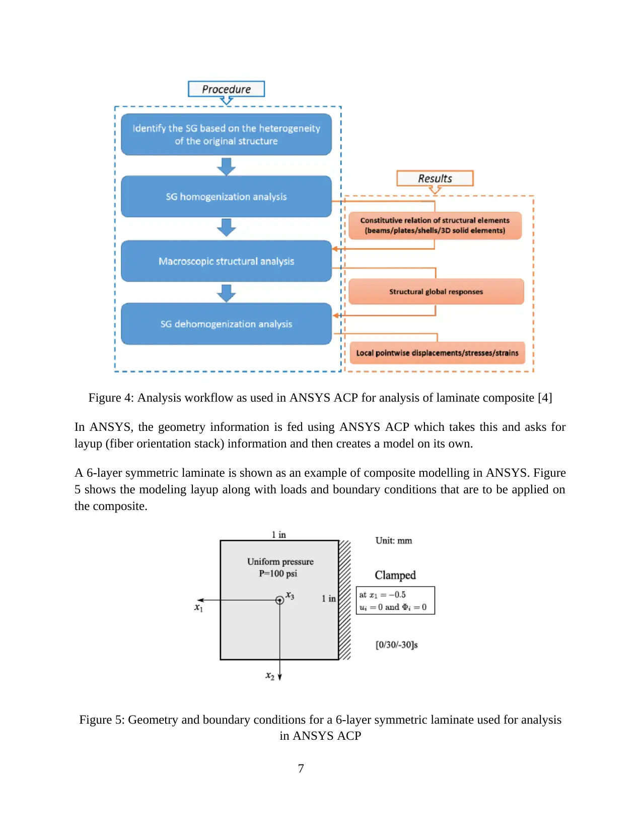
Figure 4: Analysis workflow as used in ANSYS ACP for analysis of laminate composite [4]
In ANSYS, the geometry information is fed using ANSYS ACP which takes this and asks for
layup (fiber orientation stack) information and then creates a model on its own.
A 6-layer symmetric laminate is shown as an example of composite modelling in ANSYS. Figure
5 shows the modeling layup along with loads and boundary conditions that are to be applied on
the composite.
Figure 5: Geometry and boundary conditions for a 6-layer symmetric laminate used for analysis
in ANSYS ACP
7
Paraphrase This Document
Need a fresh take? Get an instant paraphrase of this document with our AI Paraphraser
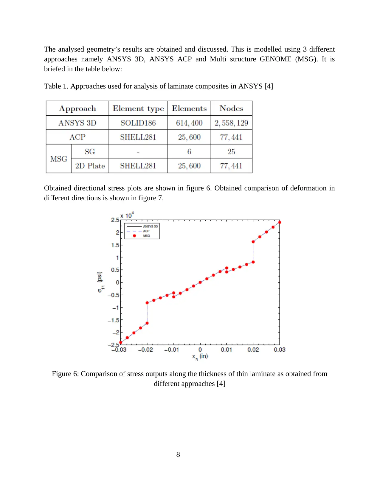
The analysed geometry’s results are obtained and discussed. This is modelled using 3 different
approaches namely ANSYS 3D, ANSYS ACP and Multi structure GENOME (MSG). It is
briefed in the table below:
Table 1. Approaches used for analysis of laminate composites in ANSYS [4]
Obtained directional stress plots are shown in figure 6. Obtained comparison of deformation in
different directions is shown in figure 7.
Figure 6: Comparison of stress outputs along the thickness of thin laminate as obtained from
different approaches [4]
8
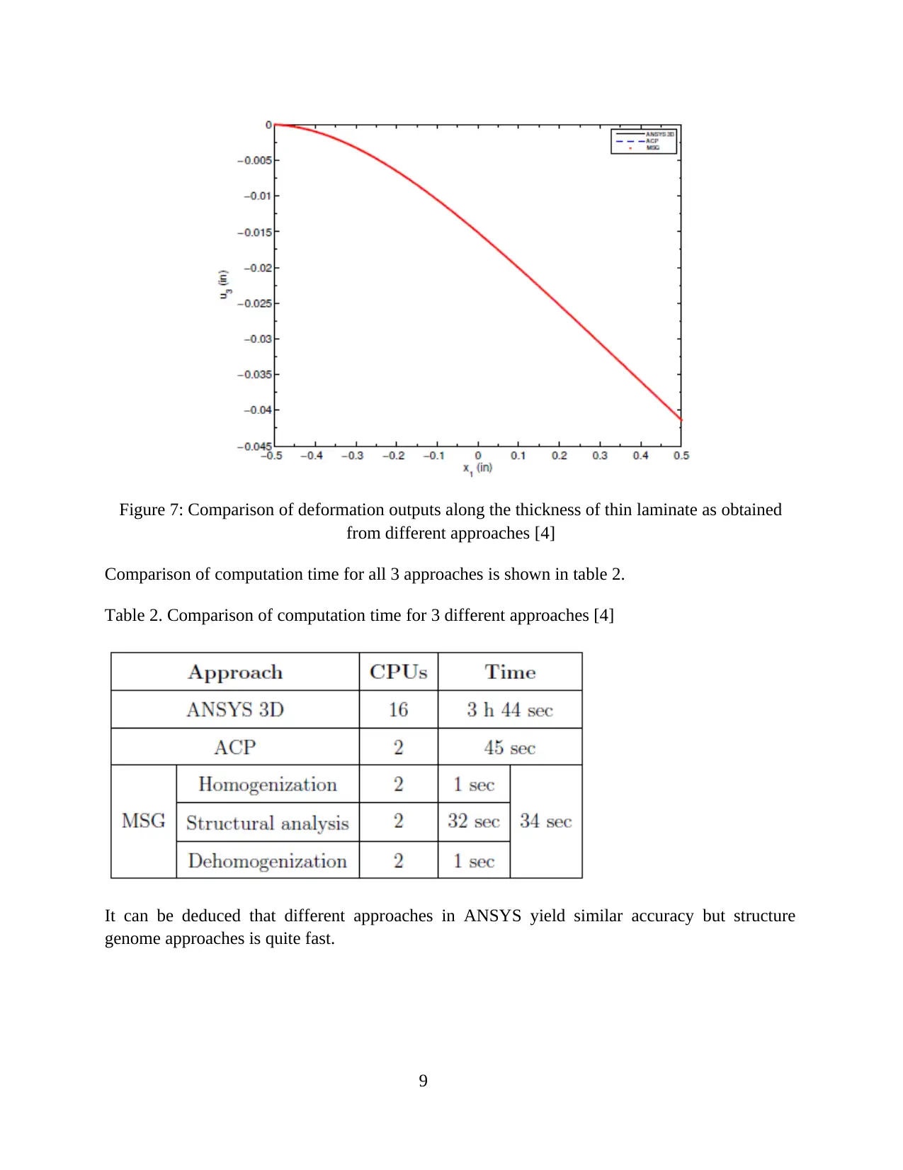
Figure 7: Comparison of deformation outputs along the thickness of thin laminate as obtained
from different approaches [4]
Comparison of computation time for all 3 approaches is shown in table 2.
Table 2. Comparison of computation time for 3 different approaches [4]
It can be deduced that different approaches in ANSYS yield similar accuracy but structure
genome approaches is quite fast.
9
from different approaches [4]
Comparison of computation time for all 3 approaches is shown in table 2.
Table 2. Comparison of computation time for 3 different approaches [4]
It can be deduced that different approaches in ANSYS yield similar accuracy but structure
genome approaches is quite fast.
9
⊘ This is a preview!⊘
Do you want full access?
Subscribe today to unlock all pages.
Trusted by 1+ million students worldwide
1 out of 14


Your All-in-One AI-Powered Toolkit for Academic Success.
+13062052269
info@desklib.com
Available 24*7 on WhatsApp / Email
![[object Object]](/_next/static/media/star-bottom.7253800d.svg)
Unlock your academic potential
Copyright © 2020–2026 A2Z Services. All Rights Reserved. Developed and managed by ZUCOL.