Composite Springs: Material Evaluation and Leaf Spring Behavior Study
VerifiedAdded on 2023/06/04
|19
|3673
|200
Report
AI Summary
This research paper investigates the behavior of composite leaf springs, focusing on material evaluation and optimization techniques. The study explores the potential of replacing steel springs with composite alternatives to reduce weight while maintaining strength and stiffness. The report covers the preliminary and detailed design of composite leaf springs, highlighting a potential mass reduction of up to 85% compared to conventional steel springs. The analysis includes evaluations of total deflection, strain energy, and stress using ANSYS software, with the aim of identifying materials with superior specific strain energy capacity. The findings suggest that composite structures offer improved strain energy storage and strength-to-mass ratios compared to steel springs, making them suitable for various automotive applications where weight reduction and performance are critical. Desklib provides access to this and other solved assignments to aid students in their studies.

Composite Springs 1
FINDING THE BEHAVIOR OF LEAF SPRING BY EVALUATING A RANGE OF
MATERIAL WITH AN OPTIMAL COMPOSITE
A Research Paper on Springs By
Student’s Name
Name of the Professor
Institutional Affiliation
City/State
Year/Month/Day
FINDING THE BEHAVIOR OF LEAF SPRING BY EVALUATING A RANGE OF
MATERIAL WITH AN OPTIMAL COMPOSITE
A Research Paper on Springs By
Student’s Name
Name of the Professor
Institutional Affiliation
City/State
Year/Month/Day
Paraphrase This Document
Need a fresh take? Get an instant paraphrase of this document with our AI Paraphraser
Composite Springs 2
ABSTRACT
In this paper, the composite materials for the structures have many benefits because of their
stiffness and strength. The automobile industry has shown the interest in the replacement if the
steel springs with the composite springs due to the great strength to the mass ratio. The designs
were selected and studied with the aim of reducing weight of composite springs using some
materials. The research paper has covered the preliminary and detailed design of the composites
leaves springs. It is noted that the mass decrease of the composite leaf spring is attained up to
85% in the situation of the composite than the conventional steel. It can be seen that the materials
with lesser density and modulus will have the more specific capacity of the strain energy. The
innovation of the composite structures was to make it likely to decrease the mass of the spring
minus any decline in the capacity of the load and rigidity. Because the composite structures have
a greater capacity for storing the strain energy and great strength to the mass ratio as related to
the spring made of steel. It is detected that the composites structures display much bend and
strain than the steel materials
Composite Springs 3
Table of Contents
ABSTRACT....................................................................................................................................................2
INTRODUCTION...........................................................................................................................................4
LITERATURE REVIEW....................................................................................................................................4
Composite materials for leaf spring.........................................................................................................4
Optimization and design of a leaf spring.................................................................................................6
Composite leaf spring..................................................................................................................................7
Design and optimization for composite spring........................................................................................9
Study of the composite spring using the ANSYS......................................................................................9
EVALUATION AND RESULTS.......................................................................................................................10
Total deflection......................................................................................................................................10
Strain energy.........................................................................................................................................11
stress.....................................................................................................................................................12
DISCUSSION...............................................................................................................................................13
APPLICATIONS...........................................................................................................................................14
CONCLUSION.............................................................................................................................................14
BIBLIOGRAPHY...........................................................................................................................................15
⊘ This is a preview!⊘
Do you want full access?
Subscribe today to unlock all pages.
Trusted by 1+ million students worldwide
Composite Springs 4
INTRODUCTION
Originally knowns as the carriage or laminated spring, a spring of leaf is a spring type that is
applied for the interruption in the wheeled vehicles. It is the ancient forms of springs from the
feudal times and it takes the arrangement of the arc-shaped slim length of the spring of steel and
the cross-section of a cylinder. The Centre of the arch gives the position for the axle that ties the
hole known as the eyes given at an end of the attributing body of the vehicle. For the weighty
vehicles, the leaf mechanism can be made from many leaves fixed on top of every other
numerous stratums. Leaf springs can be attached to the frame directly at the front end and other
end attaching through the bond, a small swaying arm. The shackle takes the leaf spring’s
tendency to lengthen when compacted and hence makes the softer springiness. The automobile
business exploring the composite constituents for the construction of the essential components to
attain the decrease in weights minus reducing the vehicle reliability, quality and also to
economize the energy and conserve natural resources.
LITERATURE REVIEW
This section has been grouped into 3 major groups: composite components for leaf spring,
optimization and the design of composite spring, and analysis of the spring made with composite
materials (Aeronautics, 2010).
Composite materials for leaf spring
A composite structure is well-known as a material comprised of the 2 or even numerous
constituent joined on the microscopic measure by the chemical and mechanical bonds.
Paraphrase This Document
Need a fresh take? Get an instant paraphrase of this document with our AI Paraphraser
Composite Springs 5
Composite is the combination of two compounds where one of the materials is the matrix stage
which takes the form of sheets, fibres and parties and it is surrounded in other compound known
as the strengthening phase. Several composite structures give the mixture of the modulus and
strength that can be equivalent to or improved than the traditional metals. Due to their small
exact gravities, the strength to the ratio of mass and the modulus to the weight ratio of these
composite constituents are greater to those of metallic constituents (Ashby, 2016).
The weariness strength mass ratio and the fatigue destruction tolerances of various composite
covers are the best and superb. For such explanations, fiber composite has arisen as the major
group of structural components and are being known as the replacement for the metals in more
mass precarious mechanisms in the aerospace, industries and the automotive. Additional unique
property of various fiber strengthened composite is their great capacity of damping internally.
This lead to improved absorption of the vibration dynamism inside the material and impacts in
the decreased transferring of the noise to the neighbouring parts. High damping capacity of the
composite material can be useful in various automotive uses where hardness, noise and vibration
is the important matter for the well-being of the passengers (California, 2010).
The composite materials are having the distinguishing properties like great strength to mass ratio,
super exhaustion strength, superb decay resistances and advanced natural frequency so it makes
the composite materials excellent for the leaf spring. The use of the composite materials
decreases the mass of the spring minus diminishing the capacity of carrying the load and the
toughness in the vehicle suspension system. The leaf mechanism absorbs the upright vibration
because of the abnormalities by the variation in the spring refraction for the prospective power to
be kept in the leaf spring as the energy of strain is removed slowly (Deplazes, 2013).
Composite Springs 6
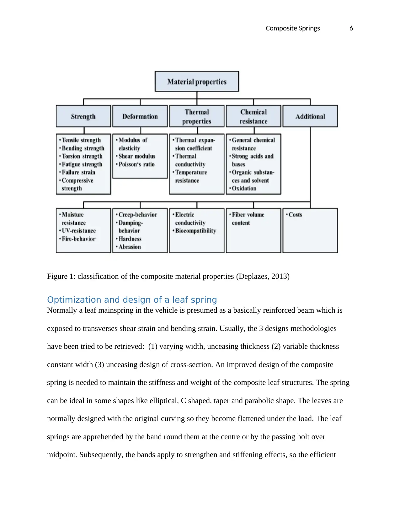
Figure 1: classification of the composite material properties (Deplazes, 2013)
Optimization and design of a leaf spring
Normally a leaf mainspring in the vehicle is presumed as a basically reinforced beam which is
exposed to transverses shear strain and bending strain. Usually, the 3 designs methodologies
have been tried to be retrieved: (1) varying width, unceasing thickness (2) variable thickness
constant width (3) unceasing design of cross-section. An improved design of the composite
spring is needed to maintain the stiffness and weight of the composite leaf structures. The spring
can be ideal in some shapes like elliptical, C shaped, taper and parabolic shape. The leaves are
normally designed with the original curving so they become flattened under the load. The leaf
springs are apprehended by the band round them at the centre or by the passing bolt over
midpoint. Subsequently, the bands apply to strengthen and stiffening effects, so the efficient
⊘ This is a preview!⊘
Do you want full access?
Subscribe today to unlock all pages.
Trusted by 1+ million students worldwide
Composite Springs 7
measurement of the spring for twisting will be the overall dimension of the spring without the
bandwidth (Fantuzzi, 2013).
In event of the centre bolts, 2/3 dimension between the midpoint of the U bolts must be deducted
from the whole dimension of the leaf spring to discover the efficient dimension. The leaf spring
is fastened and covered by the U bolts. The lengthiest leaf referred to the major leaf and has its
end designed in the eye form where the pins are approved to confident the spring to its support.
The additional leaf of the leaf spring are identified as the progressed leaves and the end of the
progressed leaf is clipped in many kinds. The reflection pins are situated at the midway position
in the leaf spring measurement for the progressed leaf to also take the strain (Hodgkinson, 2017).
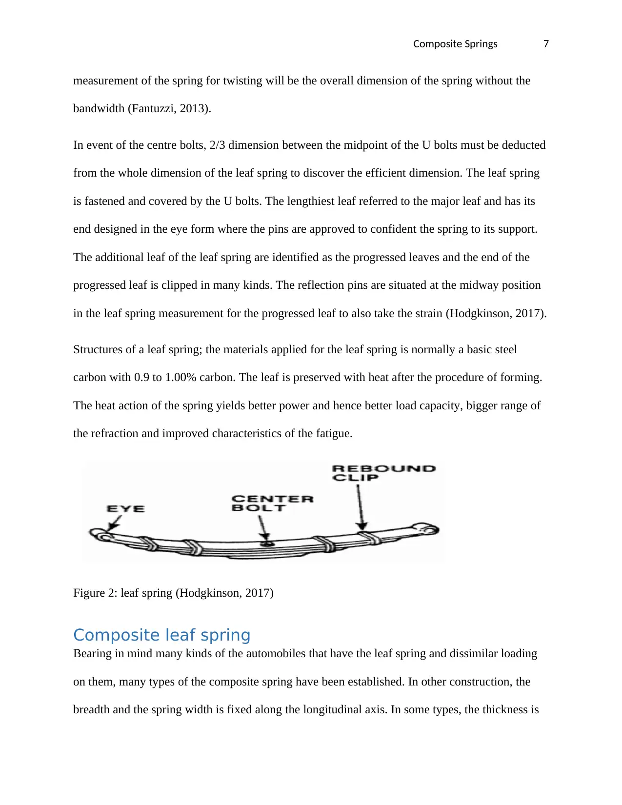
Structures of a leaf spring; the materials applied for the leaf spring is normally a basic steel
carbon with 0.9 to 1.00% carbon. The leaf is preserved with heat after the procedure of forming.
The heat action of the spring yields better power and hence better load capacity, bigger range of
the refraction and improved characteristics of the fatigue.
Figure 2: leaf spring (Hodgkinson, 2017)
Composite leaf spring
Bearing in mind many kinds of the automobiles that have the leaf spring and dissimilar loading
on them, many types of the composite spring have been established. In other construction, the
breadth and the spring width is fixed along the longitudinal axis. In some types, the thickness is
measurement of the spring for twisting will be the overall dimension of the spring without the
bandwidth (Fantuzzi, 2013).
In event of the centre bolts, 2/3 dimension between the midpoint of the U bolts must be deducted
from the whole dimension of the leaf spring to discover the efficient dimension. The leaf spring
is fastened and covered by the U bolts. The lengthiest leaf referred to the major leaf and has its
end designed in the eye form where the pins are approved to confident the spring to its support.
The additional leaf of the leaf spring are identified as the progressed leaves and the end of the
progressed leaf is clipped in many kinds. The reflection pins are situated at the midway position
in the leaf spring measurement for the progressed leaf to also take the strain (Hodgkinson, 2017).
Structures of a leaf spring; the materials applied for the leaf spring is normally a basic steel
carbon with 0.9 to 1.00% carbon. The leaf is preserved with heat after the procedure of forming.
The heat action of the spring yields better power and hence better load capacity, bigger range of
the refraction and improved characteristics of the fatigue.
Figure 2: leaf spring (Hodgkinson, 2017)
Composite leaf spring
Bearing in mind many kinds of the automobiles that have the leaf spring and dissimilar loading
on them, many types of the composite spring have been established. In other construction, the
breadth and the spring width is fixed along the longitudinal axis. In some types, the thickness is
Paraphrase This Document
Need a fresh take? Get an instant paraphrase of this document with our AI Paraphraser
Composite Springs 8
variable and the width is kept fixed beside the spring. In some kinds, the thickness is varying
hyperbolically and the width is fixed in every section so that at two boundaries the thickness is
small and in the central the thickness is high. The additional design is that the breadth and the
depth are made from the eye to the spring central and to the seat axle the breadth reduces
hyperbolically and the thickness lineally upsurges. In this construction, the curving of the spring
and misalignment of fibre in the thickness and width bearing are abandoned. Hence in this
research, the basic norms are uninvolved and the spring is made by the truthful circumstances
(Information, 2015).
Material selection
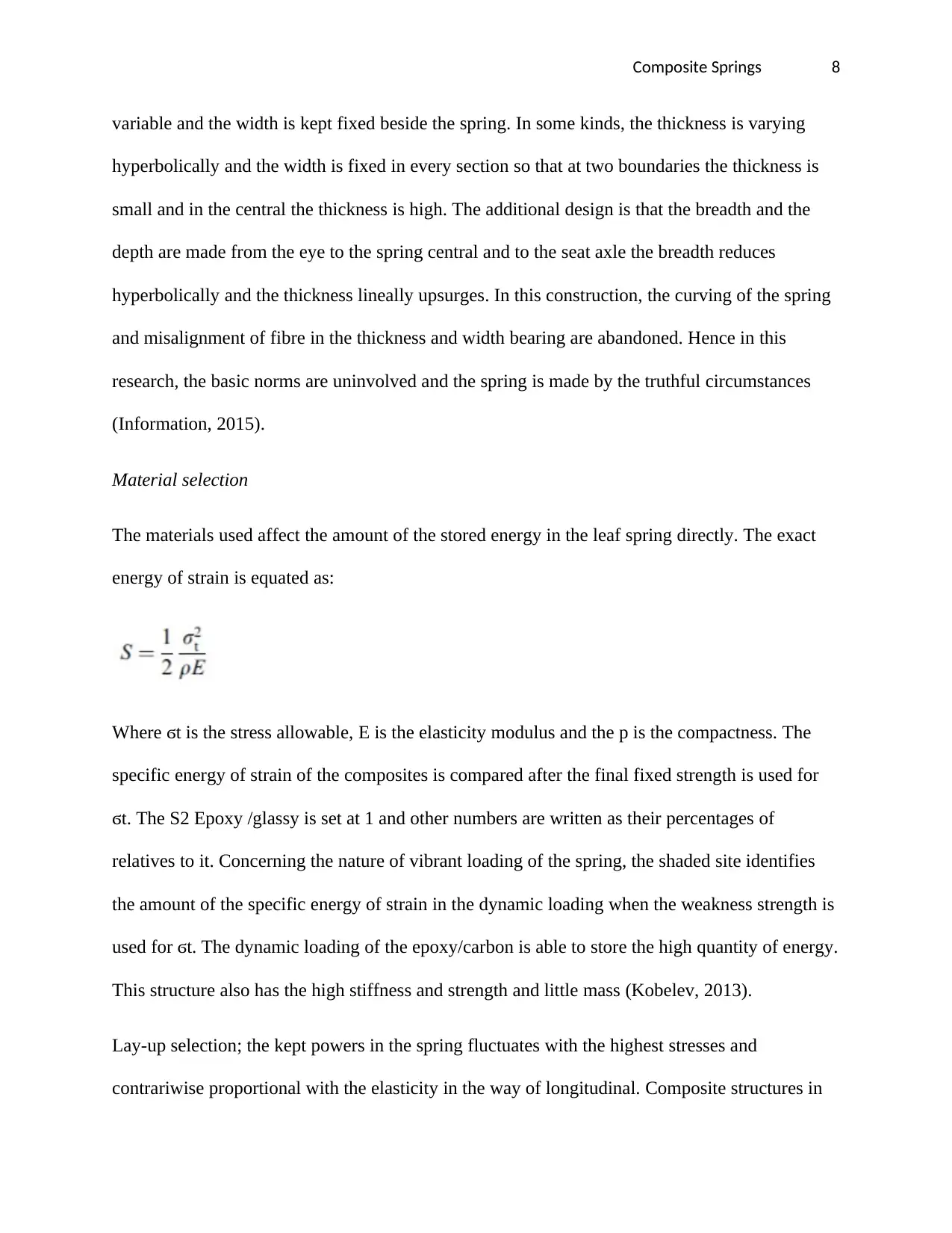
The materials used affect the amount of the stored energy in the leaf spring directly. The exact
energy of strain is equated as:
Where ϭt is the stress allowable, E is the elasticity modulus and the p is the compactness. The
specific energy of strain of the composites is compared after the final fixed strength is used for
ϭt. The S2 Epoxy /glassy is set at 1 and other numbers are written as their percentages of
relatives to it. Concerning the nature of vibrant loading of the spring, the shaded site identifies
the amount of the specific energy of strain in the dynamic loading when the weakness strength is
used for ϭt. The dynamic loading of the epoxy/carbon is able to store the high quantity of energy.
This structure also has the high stiffness and strength and little mass (Kobelev, 2013).
Lay-up selection; the kept powers in the spring fluctuates with the highest stresses and
contrariwise proportional with the elasticity in the way of longitudinal. Composite structures in
variable and the width is kept fixed beside the spring. In some kinds, the thickness is varying
hyperbolically and the width is fixed in every section so that at two boundaries the thickness is
small and in the central the thickness is high. The additional design is that the breadth and the
depth are made from the eye to the spring central and to the seat axle the breadth reduces
hyperbolically and the thickness lineally upsurges. In this construction, the curving of the spring
and misalignment of fibre in the thickness and width bearing are abandoned. Hence in this
research, the basic norms are uninvolved and the spring is made by the truthful circumstances
(Information, 2015).
Material selection
The materials used affect the amount of the stored energy in the leaf spring directly. The exact
energy of strain is equated as:
Where ϭt is the stress allowable, E is the elasticity modulus and the p is the compactness. The
specific energy of strain of the composites is compared after the final fixed strength is used for
ϭt. The S2 Epoxy /glassy is set at 1 and other numbers are written as their percentages of
relatives to it. Concerning the nature of vibrant loading of the spring, the shaded site identifies
the amount of the specific energy of strain in the dynamic loading when the weakness strength is
used for ϭt. The dynamic loading of the epoxy/carbon is able to store the high quantity of energy.
This structure also has the high stiffness and strength and little mass (Kobelev, 2013).
Lay-up selection; the kept powers in the spring fluctuates with the highest stresses and
contrariwise proportional with the elasticity in the way of longitudinal. Composite structures in
Composite Springs 9
the fibres direction have well propertied for the storage of the strain. Hence the lay-up is chosen
to the one direction alongside the longitudinal way of the spring. This lay-up chosen might
decline the spring at the areas of powered joints and need reinforcing the spring in the regions.
Design and optimization for composite spring
By broad application of covered combined structures in every field of manufacturing, the optical
construction of the layered composite has remained broad subjects of the study. Because the
composite spring, it is significant to improve the profile of the spring. The person designing
should make the choices concerning the assortment of the geometry that is optimum. This needs
the confirmation of many dissimilar complex explanations. Consequently, the advancement is
done out with the FEM using software of ANSYS. A 3D brick element can be used for the
modelling of the curved, thick and orthotropic structures, the 3 dimension fundamentals of shells
are used for the assemblies that are thin. In the central composite springs, the breadth will be
raised about the 1/2 of the width of the spring to repeal the high winding moment practical in this
capacity. Considering the unidirectional lay-up of the composite leaf spring, 3dimensional eight-
node element brick was chosen to advance a FEM of the spring (Kollár, 2010).
Study of the composite spring using the ANSYS
All the investigation of the springs is completed by the software of ANSYS for the composite
spring the similar restrictions are applied as that of the steel spring. For the design of the spring,
the arc is taken as 200mm. The spring is moulded in software of CATIA and moved to the
ANSYS software. The problems are given at the two-eyed bowled ends. One of the ends is
given with the translational movement to adjust with the deflection and the eye is allowed to
move in the longitudinal directions. This specific movement helps the leaf spring to become
compressed when applying the loads. The deflection and stress study is done for the composite
and conventional steel leaf spring using the ANSYS software (Mallick, 2011)
⊘ This is a preview!⊘
Do you want full access?
Subscribe today to unlock all pages.
Trusted by 1+ million students worldwide
Composite Springs 10
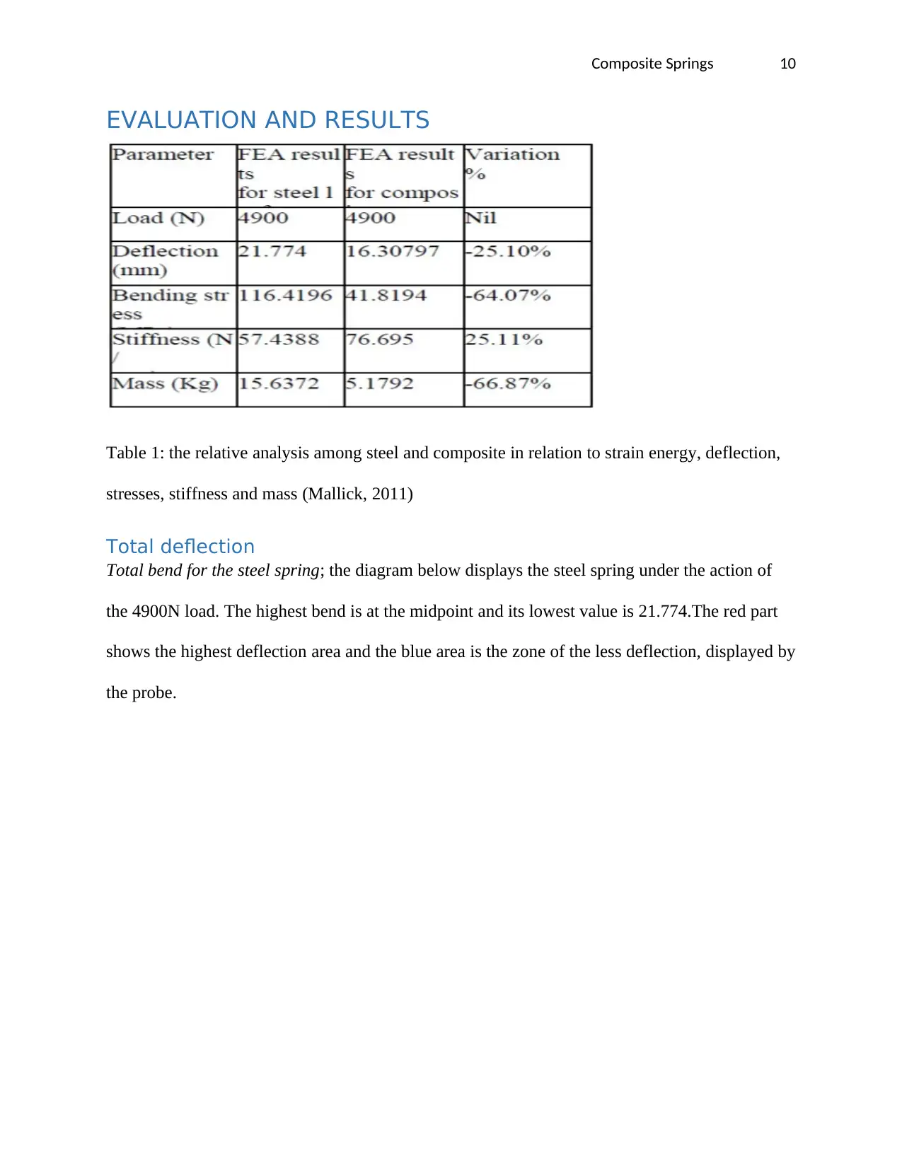
EVALUATION AND RESULTS
Table 1: the relative analysis among steel and composite in relation to strain energy, deflection,
stresses, stiffness and mass (Mallick, 2011)
Total deflection
Total bend for the steel spring; the diagram below displays the steel spring under the action of
the 4900N load. The highest bend is at the midpoint and its lowest value is 21.774.The red part
shows the highest deflection area and the blue area is the zone of the less deflection, displayed by
the probe.
Paraphrase This Document
Need a fresh take? Get an instant paraphrase of this document with our AI Paraphraser
Composite Springs 11
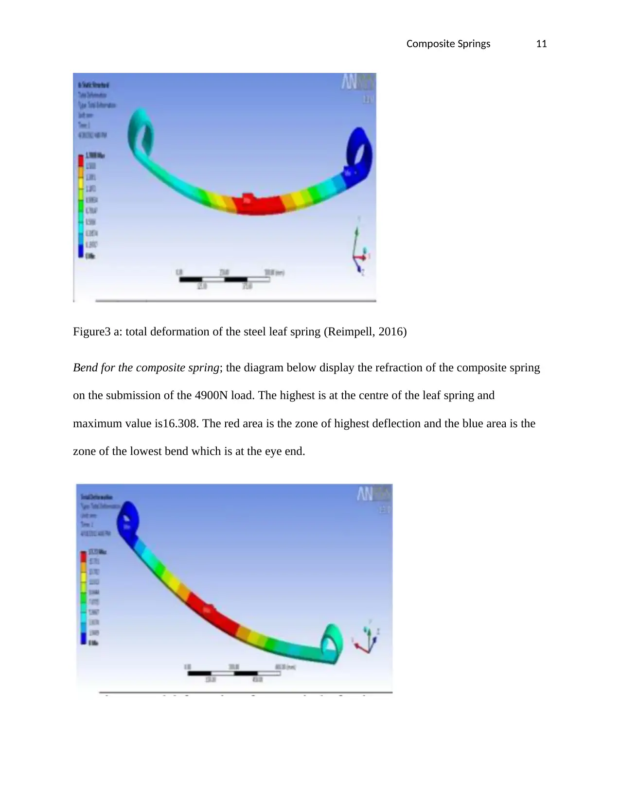
Figure3 a: total deformation of the steel leaf spring (Reimpell, 2016)
Bend for the composite spring; the diagram below display the refraction of the composite spring
on the submission of the 4900N load. The highest is at the centre of the leaf spring and
maximum value is16.308. The red area is the zone of highest deflection and the blue area is the
zone of the lowest bend which is at the eye end.
Composite Springs 12
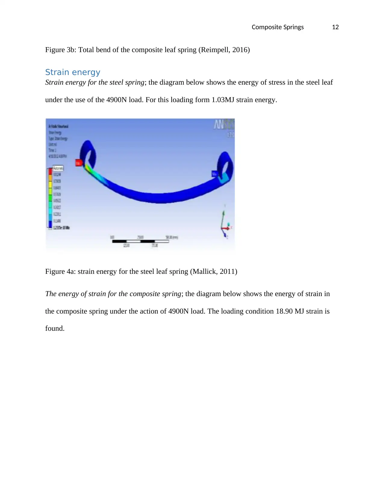
Figure 3b: Total bend of the composite leaf spring (Reimpell, 2016)
Strain energy
Strain energy for the steel spring; the diagram below shows the energy of stress in the steel leaf
under the use of the 4900N load. For this loading form 1.03MJ strain energy.
Figure 4a: strain energy for the steel leaf spring (Mallick, 2011)
The energy of strain for the composite spring; the diagram below shows the energy of strain in
the composite spring under the action of 4900N load. The loading condition 18.90 MJ strain is
found.
⊘ This is a preview!⊘
Do you want full access?
Subscribe today to unlock all pages.
Trusted by 1+ million students worldwide
1 out of 19
Related Documents


Your All-in-One AI-Powered Toolkit for Academic Success.
+13062052269
info@desklib.com
Available 24*7 on WhatsApp / Email
![[object Object]](/_next/static/media/star-bottom.7253800d.svg)
Unlock your academic potential
Copyright © 2020–2026 A2Z Services. All Rights Reserved. Developed and managed by ZUCOL.