EAT216: Computer-Aided Engineering Carabiner Design Report

Verified

Added on  2022/07/28

|6
|724
|13
Report
AI Summary
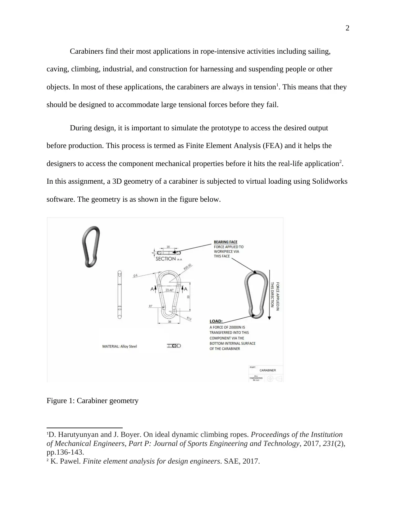
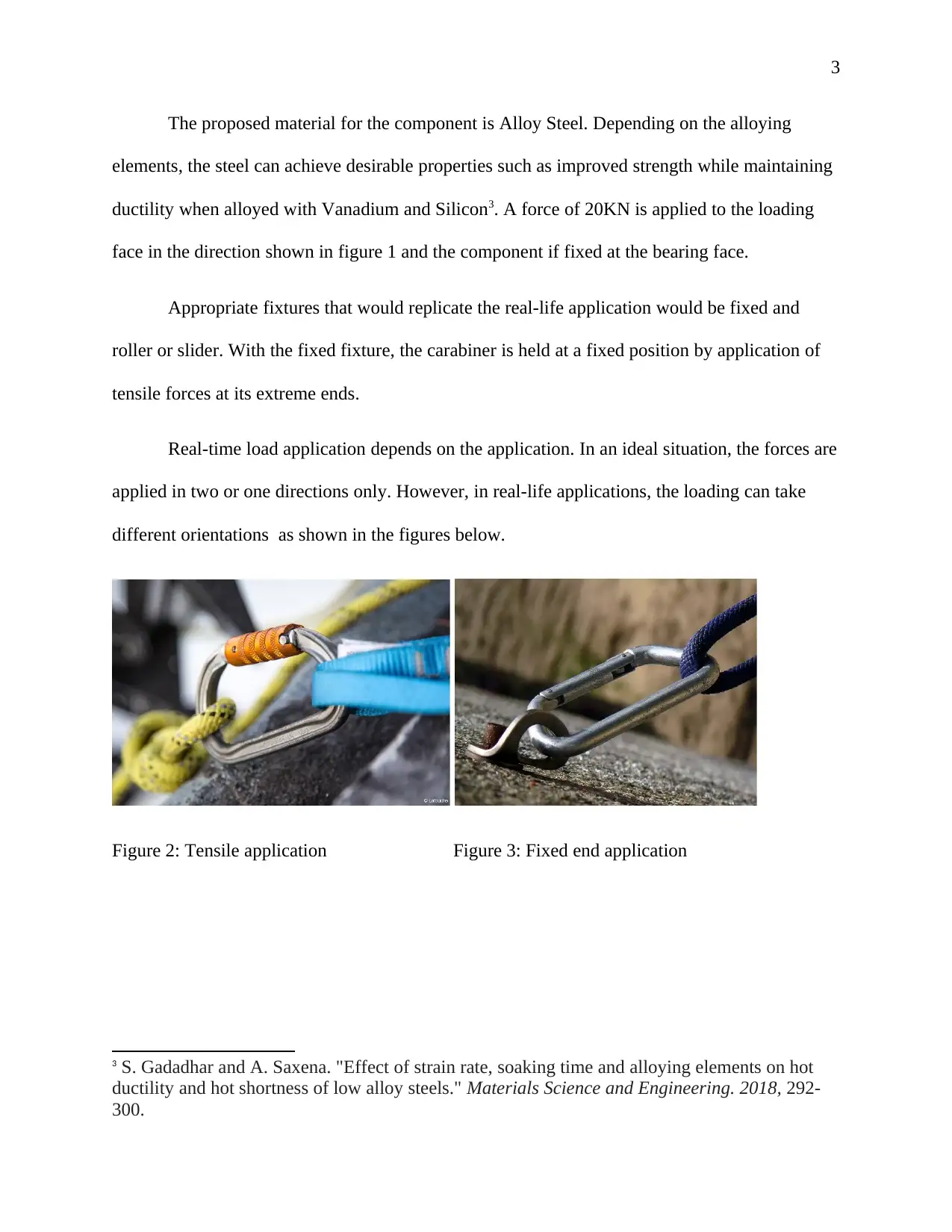
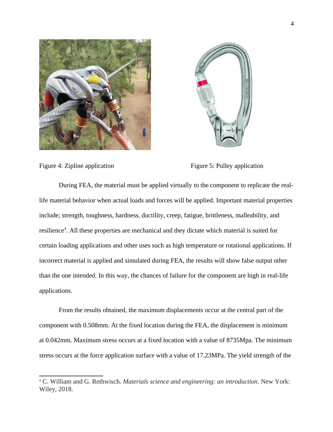
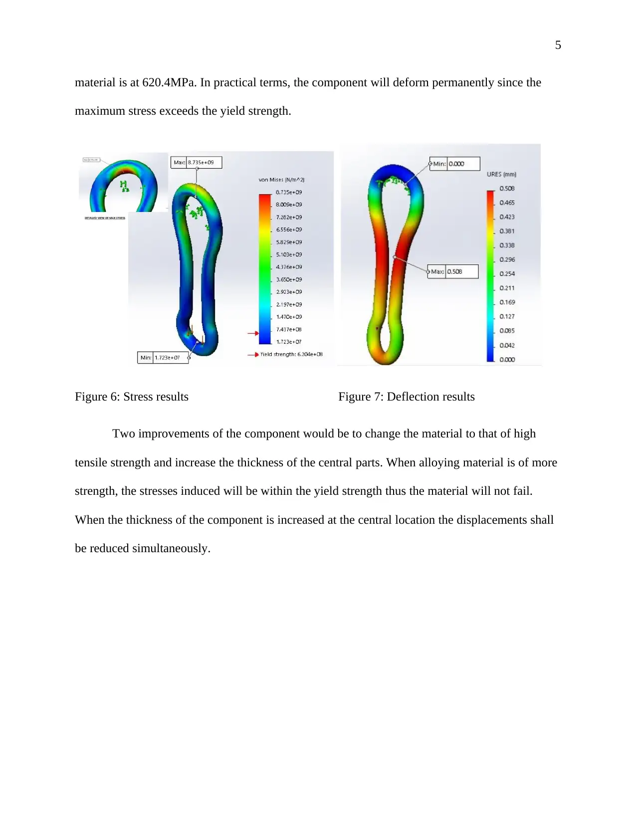
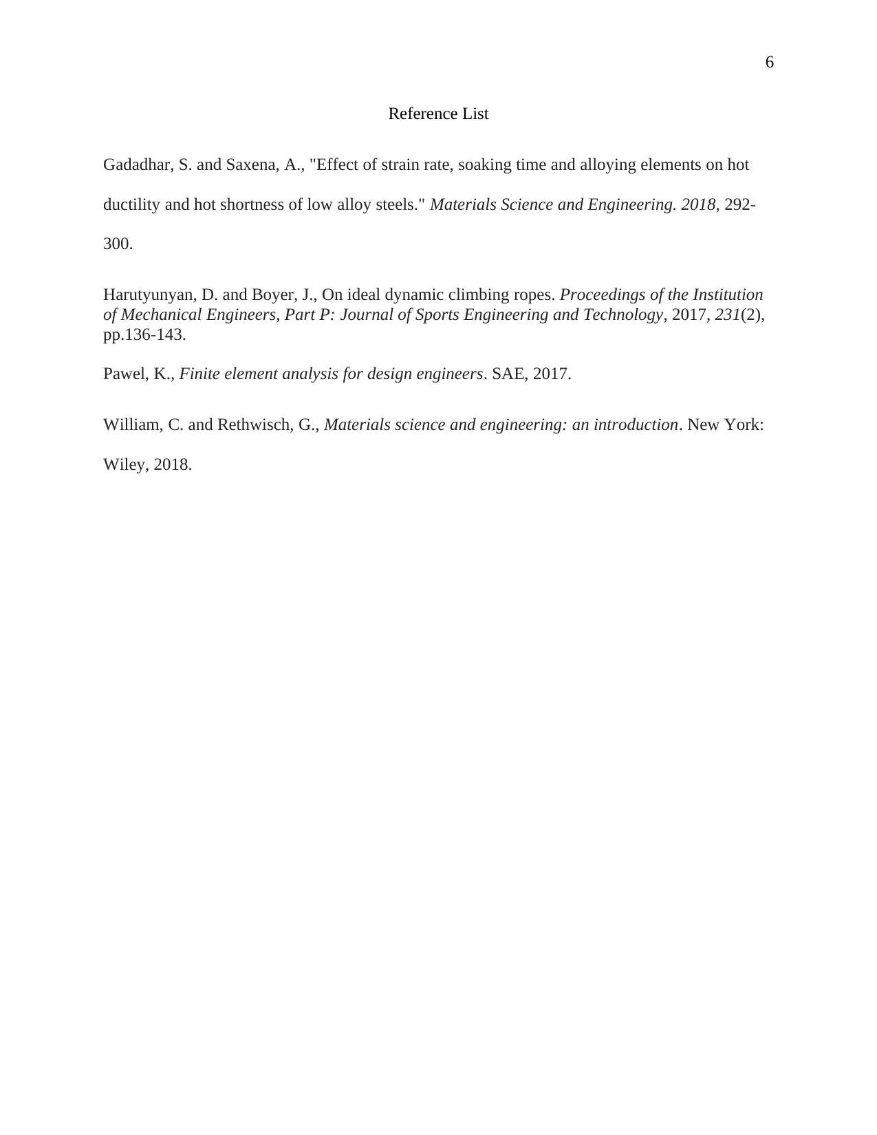
This report presents a Computer-Aided Engineering (CAE) analysis of a carabiner, focusing on its design and performance under load. The study utilizes Finite Element Analysis (FEA) within Solidworks software to simulate the behavior of an alloy steel carabiner subjected to a 20KN force. The analysis includes detailed diagrams of the carabiner's geometry, loading conditions, and fixture setups, replicating real-world applications such as tensile, fixed-end, zipline, and pulley scenarios. Key material properties, including strength and ductility, are discussed in the context of their impact on the simulation results. The report highlights the stress and deflection results, with maximum displacement at the central part of the component and maximum stress at a fixed location, and compares these values against the material's yield strength to assess the component's structural integrity. The report concludes with recommendations for design improvements, such as using a higher tensile strength material and increasing the thickness of the central part to enhance the carabiner's performance. The report references relevant literature on material properties and FEA techniques.
Document Page
1
Computer-Aided Engineering
Design Report
Date
Words
Student’s Name
Institutional Affiliation
tabler-icon-diamond-filled.svg

Secure Best Marks with AI Grader

Need help grading? Try our AI Grader for instant feedback on your assignments.
Document Page
2
Carabiners find their most applications in rope-intensive activities including sailing,
caving, climbing, industrial, and construction for harnessing and suspending people or other
objects. In most of these applications, the carabiners are always in tension1. This means that they
should be designed to accommodate large tensional forces before they fail.
During design, it is important to simulate the prototype to access the desired output
before production. This process is termed as Finite Element Analysis (FEA) and it helps the
designers to access the component mechanical properties before it hits the real-life application2.
In this assignment, a 3D geometry of a carabiner is subjected to virtual loading using Solidworks
software. The geometry is as shown in the figure below.
Figure 1: Carabiner geometry
1D. Harutyunyan and J. Boyer. On ideal dynamic climbing ropes. Proceedings of the Institution
of Mechanical Engineers, Part P: Journal of Sports Engineering and Technology, 2017, 231(2),
pp.136-143.
2 K. Pawel. Finite element analysis for design engineers. SAE, 2017.
Document Page
3
The proposed material for the component is Alloy Steel. Depending on the alloying
elements, the steel can achieve desirable properties such as improved strength while maintaining
ductility when alloyed with Vanadium and Silicon3. A force of 20KN is applied to the loading
face in the direction shown in figure 1 and the component if fixed at the bearing face.
Appropriate fixtures that would replicate the real-life application would be fixed and
roller or slider. With the fixed fixture, the carabiner is held at a fixed position by application of
tensile forces at its extreme ends.
Real-time load application depends on the application. In an ideal situation, the forces are
applied in two or one directions only. However, in real-life applications, the loading can take
different orientations as shown in the figures below.
Figure 2: Tensile application Figure 3: Fixed end application
3 S. Gadadhar and A. Saxena. "Effect of strain rate, soaking time and alloying elements on hot
ductility and hot shortness of low alloy steels." Materials Science and Engineering. 2018, 292-
300.
Document Page
4
Figure 4: Zipline application Figure 5: Pulley application
During FEA, the material must be applied virtually to the component to replicate the real-
life material behavior when actual loads and forces will be applied. Important material properties
include; strength, toughness, hardness, ductility, creep, fatigue, brittleness, malleability, and
resilience4. All these properties are mechanical and they dictate which material is suited for
certain loading applications and other uses such as high temperature or rotational applications. If
incorrect material is applied and simulated during FEA, the results will show false output other
than the one intended. In this way, the chances of failure for the component are high in real-life
applications.
From the results obtained, the maximum displacements occur at the central part of the
component with 0.508mm. At the fixed location during the FEA, the displacement is minimum
at 0.042mm. Maximum stress occurs at a fixed location with a value of 8735Mpa. The minimum
stress occurs at the force application surface with a value of 17.23MPa. The yield strength of the
4 C. William and G. Rethwisch. Materials science and engineering: an introduction. New York:
Wiley, 2018.
tabler-icon-diamond-filled.svg

Secure Best Marks with AI Grader

Need help grading? Try our AI Grader for instant feedback on your assignments.
Document Page
5
material is at 620.4MPa. In practical terms, the component will deform permanently since the
maximum stress exceeds the yield strength.
Figure 6: Stress results Figure 7: Deflection results
Two improvements of the component would be to change the material to that of high
tensile strength and increase the thickness of the central parts. When alloying material is of more
strength, the stresses induced will be within the yield strength thus the material will not fail.
When the thickness of the component is increased at the central location the displacements shall
be reduced simultaneously.
Document Page
6
Reference List
Gadadhar, S. and Saxena, A., "Effect of strain rate, soaking time and alloying elements on hot
ductility and hot shortness of low alloy steels." Materials Science and Engineering. 2018, 292-
300.
Harutyunyan, D. and Boyer, J., On ideal dynamic climbing ropes. Proceedings of the Institution
of Mechanical Engineers, Part P: Journal of Sports Engineering and Technology, 2017, 231(2),
pp.136-143.
Pawel, K., Finite element analysis for design engineers. SAE, 2017.
William, C. and Rethwisch, G., Materials science and engineering: an introduction. New York:
Wiley, 2018.
chevron_up_icon
1 out of 6
circle_padding
hide_on_mobile
zoom_out_icon
[object Object]