Computer Organization and Architecture: Logic Circuit Analysis Report

Verified

Added on  2022/08/21

|4
|725
|15
Report
AI Summary
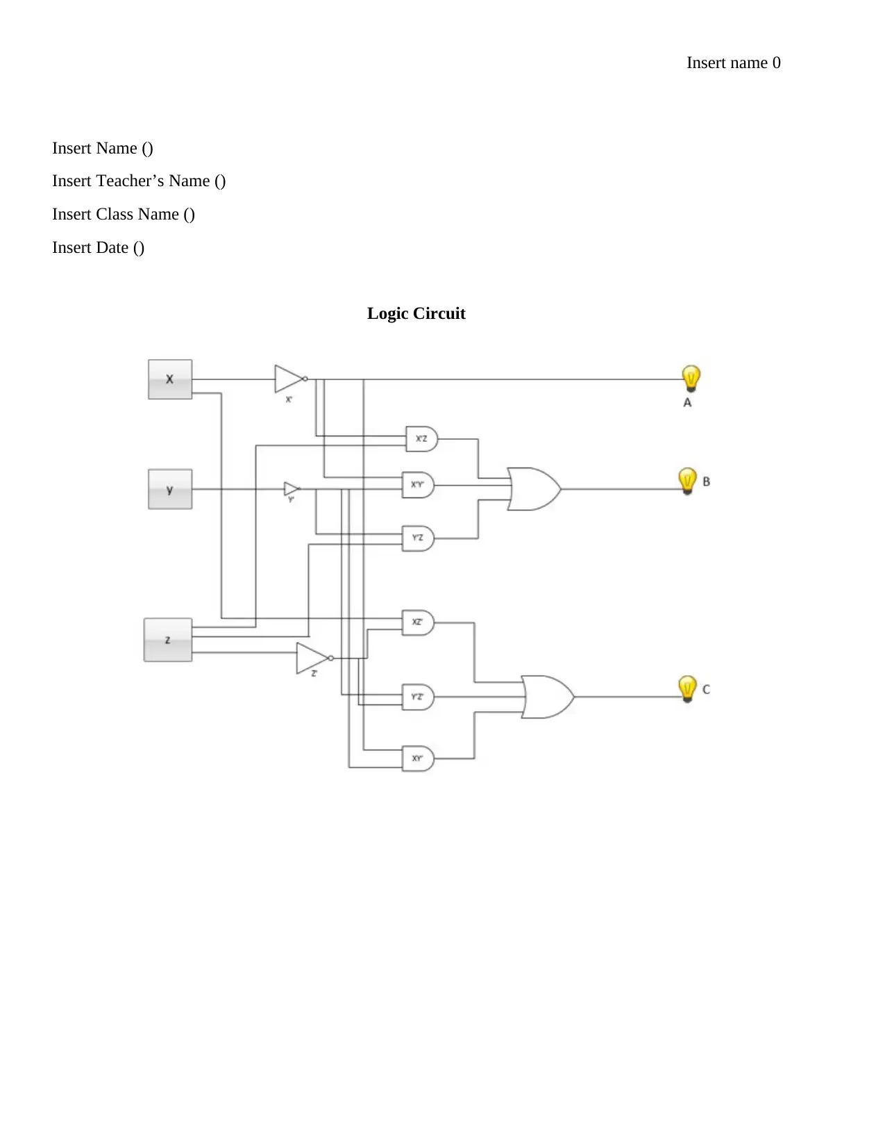
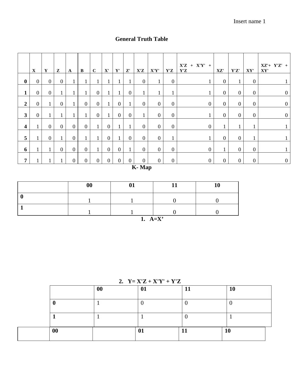
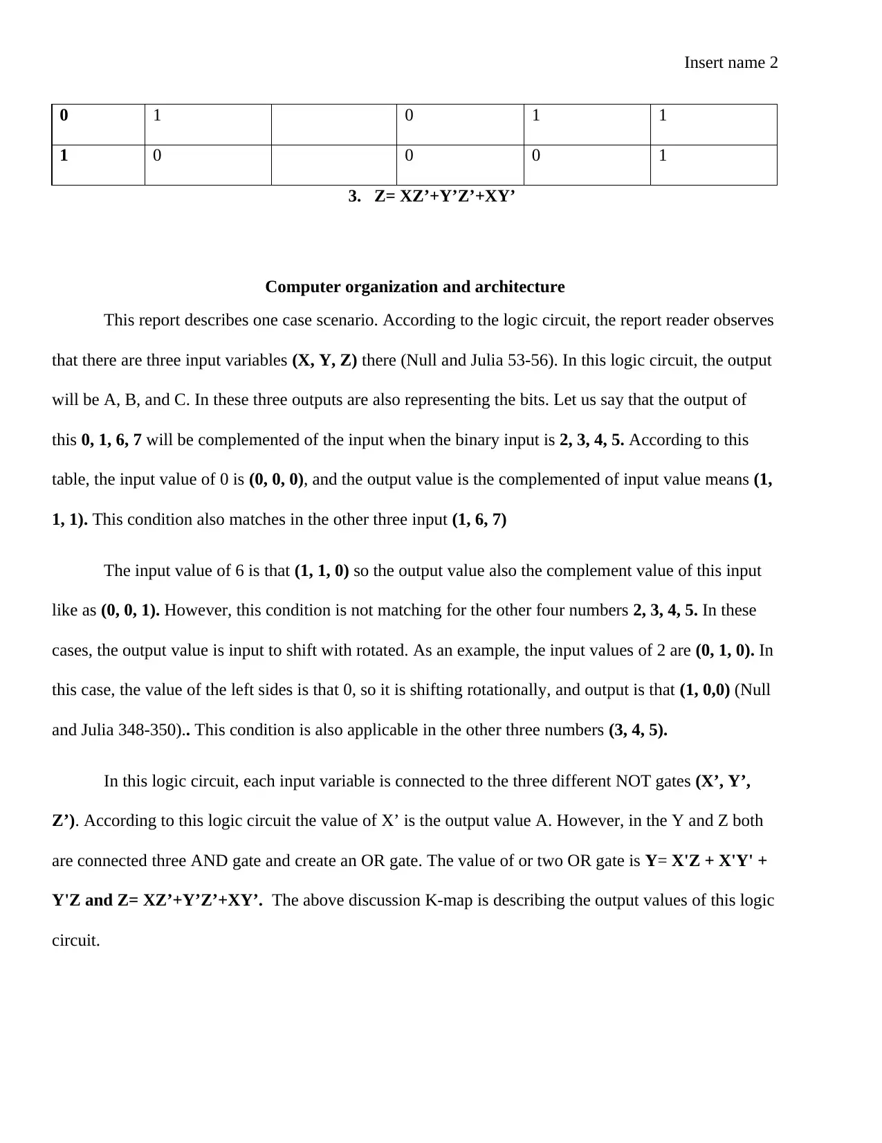
This report provides an analysis of a logic circuit within the context of computer organization and architecture. It examines a circuit with three input variables (X, Y, Z) and three output variables (A, B, C). The report details the relationship between inputs and outputs, highlighting how specific input combinations result in complemented or rotated outputs based on the provided truth table. The analysis includes the application of NOT gates, AND gates, and OR gates to determine the output values. The report also references K-maps to represent the output values of the logic circuit. The report refers to a source to support the analysis of the logic circuit.
Document Page
Insert name 0
Insert Name ()
Insert Teacher’s Name ()
Insert Class Name ()
Insert Date ()
Logic Circuit
tabler-icon-diamond-filled.svg

Paraphrase This Document

Need a fresh take? Get an instant paraphrase of this document with our AI Paraphraser
Document Page
Insert name 1
General Truth Table
X Y Z A B C X' Y' Z' X'Z X'Y' Y'Z
X'Z + X'Y' +
Y'Z XZ' Y'Z' XY'
XZ'+ Y'Z' +
XY'
0 0 0 0 1 1 1 1 1 1 0 1 0 1 0 1 0 1
1 0 0 1 1 1 0 1 1 0 1 1 1 1 0 0 0 0
2 0 1 0 1 0 0 1 0 1 0 0 0 0 0 0 0 0
3 0 1 1 1 1 0 1 0 0 1 0 0 1 0 0 0 0
4 1 0 0 0 0 1 0 1 1 0 0 0 0 1 1 1 1
5 1 0 1 0 1 1 0 1 0 0 0 1 1 0 0 1 1
6 1 1 0 0 0 1 0 0 1 0 0 0 0 1 0 0 1
7 1 1 1 0 0 0 0 0 0 0 0 0 0 0 0 0 0
K- Map
00 01 11 10
0 1 1 0 0
1 1 1 0 0
1. A=X’
2. Y= X'Z + X'Y' + Y'Z
00 01 11 10
00 01 11 10
0 1 0 0 0
1 1 1 0 1
Document Page
Insert name 2
0 1 0 1 1
1 0 0 0 1
3. Z= XZ’+Y’Z’+XY’
Computer organization and architecture
This report describes one case scenario. According to the logic circuit, the report reader observes
that there are three input variables (X, Y, Z) there (Null and Julia 53-56). In this logic circuit, the output
will be A, B, and C. In these three outputs are also representing the bits. Let us say that the output of
this 0, 1, 6, 7 will be complemented of the input when the binary input is 2, 3, 4, 5. According to this
table, the input value of 0 is (0, 0, 0), and the output value is the complemented of input value means (1,
1, 1). This condition also matches in the other three input (1, 6, 7)
The input value of 6 is that (1, 1, 0) so the output value also the complement value of this input
like as (0, 0, 1). However, this condition is not matching for the other four numbers 2, 3, 4, 5. In these
cases, the output value is input to shift with rotated. As an example, the input values of 2 are (0, 1, 0). In
this case, the value of the left sides is that 0, so it is shifting rotationally, and output is that (1, 0,0) (Null
and Julia 348-350).. This condition is also applicable in the other three numbers (3, 4, 5).
In this logic circuit, each input variable is connected to the three different NOT gates (X’, Y’,
Z’). According to this logic circuit the value of X’ is the output value A. However, in the Y and Z both
are connected three AND gate and create an OR gate. The value of or two OR gate is Y= X'Z + X'Y' +
Y'Z and Z= XZ’+Y’Z’+XY’. The above discussion K-map is describing the output values of this logic
circuit.
Document Page
Insert name 3
Works Cited
Null, Linda, and Julia Lobur. The essentials of computer organization and architecture. Jones & Bartlett
Publishers, 2014.
chevron_up_icon
1 out of 4
circle_padding
hide_on_mobile
zoom_out_icon
[object Object]