Computer Dynamics Network Design and Implementation Report
VerifiedAdded on 2023/06/15
|22
|4008
|134
Report
AI Summary
This report assesses Computer Dynamics' existing network infrastructure, which suffers from congestion, lack of physical connection between two buildings, and inefficient VPN setup. It analyzes user requirements across various departments, estimates capacity, and proposes a new network design featuring a fiber optic cable connection between buildings and layer 3 switching for improved data transfer. The report includes a cost estimation and recommendations for enhancing network performance and disaster recovery. The goal is to provide a scalable network solution that meets the company's current and future needs, ensuring efficient data communication and supporting business growth. Desklib provides access to this and other solved assignments for students.

COMPUTER DYNAMIC NETWORK DESIGN REPORT
PREPARED BY:
XXXXXXXX
2ND February,2018
1
PREPARED BY:
XXXXXXXX
2ND February,2018
1
Paraphrase This Document
Need a fresh take? Get an instant paraphrase of this document with our AI Paraphraser
Executive Summary
Computer Dynamics currently uses a network that does not have a physical connection between
the two buildings that the company uses and the network is also overloaded, this creates the basis
of the report which includes assessing the existing network infrastructure, where the
management and the users of the network being interviewed and offer the solution that is recent
enough and can overcome this critical problem hence meeting the company’s needs.
It was found that, the existing network is overloaded and congested, slow and therefore cannot
support the growth of the business with relation to increased number of projects that are being
created . Physical connection between the two buildings occupied by the organization is not their
hence the two are sharing information across VPN site to site tunnel which is not efficient.
It was therefore recommended that a physical connection is required to connect between the two
buildings; this can use fiber optic cable for connection. Three layer switching is applied to this
because enhances high speed in data transfer between the components in the network. The usage
of fiber optic cable between buildings enhances high data communications between the
buildings and transfer of information.
2
Contents
1.0 INTRODUCTION.................................................................................................................................5
1.1 PURPOSE.........................................................................................................................................5
1.2Background........................................................................................................................................5
1.3Scope of the report..............................................................................................................................6
2.0ANALYSIS OF USER REQUIREMENTS............................................................................................6
2.1Network users-Analysis......................................................................................................................6
2.2Managers and Working staff (pc USERS)........................................................................................6
2.3 FINANCE DEPARTMENT..................................................................................................................7
2.4 MARKETING DEPARTMENT........................................................................................................7
2.5 IMPLEMENTATION........................................................................................................................7
2.6 SALES DEPARTMENT...................................................................................................................8
2.7 LEGAL DEPARTMENT..................................................................................................................8
2.8 QUALITY ASSURANCE GROUP...................................................................................................8
2.9 ADMINISTRATION.........................................................................................................................9
2.9.1 INFORMATION TECHNOLOGY DEPARTMENT..................................................................9
2.9.2 GRAPHICS INTERFACE..............................................................................................................9
2.9.3 PROJECT TEAMS 1-3................................................................................................................10
2.9.4 PROJECT SUPPORT..................................................................................................................10
2.9.5 PROJECT TEAMS 4-9.................................................................................................................10
2.9.6 PROJECT SUPPORT..................................................................................................................11
2.9.7 HEAD OF SOFTWARE DEVELOPMENT & 2 ANALYSTS + SUPPORTSTAFF..................11
2.9.8 INFORMATION TECHNOLOGY (ITS) GROUP 2 (LAPTOP USERS)...................................11
2.9.9 HUMAN RESOURCES..............................................................................................................12
3.1.0 PROJECT SUPPORT.................................................................................................................12
3.1.1 PROJECT TEAMS 10-14...........................................................................................................12
3.1.2 PROJECT TEAMS 15-20...........................................................................................................12
3.1.3 PROJECT SUPPORT..................................................................................................................13
3.1.4 PROJECT TEAMS......................................................................................................................13
3.1.5 PROJECT PROVIDERS............................................................................................................13
3.0 CAPACITY ESTIMATION...............................................................................................................13
4.0 Description and analysis of the current network setup........................................................................14
5.0 Proposed Network description...........................................................................................................15
3
⊘ This is a preview!⊘
Do you want full access?
Subscribe today to unlock all pages.

Trusted by 1+ million students worldwide
5.1 Circuits............................................................................................................................................15
5.2 Hardware........................................................................................................................................15
5.3 hp 15 pc..........................................................................................................................................15
5.4 Software..........................................................................................................................................16
5.5 Server Softwares..............................................................................................................................16
5.6 Proposed network layout.................................................................................................................16
6.0 COST ESTIMATION.........................................................................................................................18
7.0 CONCLUSION AND RECOMMENTATIONS.................................................................................19
8.0 References...........................................................................................................................................20
9.0 Appendi A...........................................................................................................................................21
10.0 Appendix B........................................................................................................................................22
4
Paraphrase This Document
Need a fresh take? Get an instant paraphrase of this document with our AI Paraphraser
1.0 INTRODUCTION
1.1 PURPOSE
The core purpose of this report is to evaluate the nature of the network infrastructure that
existed before at Computer Dynamics in relation to the objectives of the organization and put
down necessary strategies to improve the network infrastructure in order to achieve the
maximum functioning of the system.
1.2Background
Computer Dynamics is a well based software company . the company has a network that existed
before and the network is currently housing three hundred computers in two different buildings.
Though the network was upgraded to a latter network infrastructure, the company as now grown
because of good marketing of the company.
In the previous network, there was no network connection between the two buildings, also the
current network has problems due to high rates of overloading of data caused by a higher
number of users and many other reasons of overloading. In any case this network is not upgraded
to a better and latest network technologies, the problem might persist because more projects are
expected in the coming days.
From the problems that the association phases it has decided to change the layout of the
network structure. Cisco has been given the task to investigate and come up with a network
layout that will be used to upgrade the network structure in the company.
5
1.3 Scope of the report
In generally the structure of the network in the company is mentioned in relation to the goal of
the business for the network. In addition, an analysis regarding the user requirements and the
network that is currently existing in the organization is critically performed . the main areas that
are covered in this report includes according to Agata(2012):
i. The requirement of the user and capacity level.
ii. The existing network infrastructure that includes diagrams.
iii. The hardware
iv. The software that is being utilized including the client, network, operating system and
importantly the server.
v. The whole network layout, they are logical and physical network topologies.
vi. The performance of the existing network.
The layout of the proposed network is stated within the report and is aimed at serving the
company for 3-5 years maintaining its high capacity. Circuitry includes connection of
infrastructure, Hardware/Devices , Software ,Network Architecture.
2.0ANALYSIS OF USER REQUIREMENTS Laner( 2010)
2.1Network users-Analysis
This part explains the users has part of the networking plan. This are the clients and
administration managers who will be using and controlling the network . It also explains the
type of applications that the user will use to access the network and make any father changes in
the network. The user type using the network can be called network traffic level which can be
either high or standard.
Building A category 1
2.2Managers and Working staff (pc USERS)
6
⊘ This is a preview!⊘
Do you want full access?
Subscribe today to unlock all pages.

Trusted by 1+ million students worldwide
Found in Building B, category 1
User type: Standard
Connected users: 2
Programs used: Emailing, Web services, Audio Conferencing, Resource sharing and general in
“office”., and malware protection .
Any file within the network should be highly secured.
2.3 FINANCE DEPARTMENT
Found in Building A, category 1
user type: High
Connected users; 8
Programs used: Emailing, Web-services, in Payrolls, sharing of files, Internet, general “office”
applications, malicious code protection and printer access.
Files that are produced by the finance group should always be secured.
2.4 MARKETING DEPARTMENT
found in Building B, category 1
User type: High
Connected members: 4
software’s used: Emailing, Web-forums, Publishing, Graphics Database, sharing of files and
Intranet
files produced are average in size hence in need of space for storage.
2.5 IMPLEMENTATION
Found in Building B, category 1
User type;High
7
Paraphrase This Document
Need a fresh take? Get an instant paraphrase of this document with our AI Paraphraser
Connected users: 11
used applications: Emailing, Web-filing, File transfer, Intranet, environmental access sharing of
software, training people, (vpn) in general “office”
applications, malware protection and printer access.
Files produced should have access restriction because the group is a mobility group and it can
create interference with the files.
2.6 SALES DEPARTMENT
Found in Building B, category 1
use type:medium
Connected users: 9
Types of services provided : Emailing, Web-forums, internet customer relationship and
Managing of software;
sharing of files, Intranet, malicious code protection and access to printers
Files produced should be highly be protected to avoid interference from other personel.
2.7 LEGAL DEPARTMENT
found in Building 2,category 1
user type ;Standard
connected users: 2
Applications being used: Emailing, Web-forums, sharing of files, Intranet, general “office”
applications, protection of virus and hardware access like printers. The documents and files that
are produced should have a high access restriction.
2.8 QUALITY ASSURANCE GROUP
Building A, category 1
user type: high
8
connected users: 2
Applications being used: Emailing, Web-forums, sharing of files, Intranet, general “office”
applications, protection of virus and hardware access like printers. The documents and files that
are produced should have a high access restriction.
2.9 ADMINISTRATION
Found Building B, category 1
user type: medium
connected users: 2
used applications: Emailing, Web-filing, File transfer, Intranet, environmental access sharing of
software, training people, (vpn) in general “office”
applications, malware protection and printer access.
Managing and controlling the all network.
2.9.1 INFORMATION TECHNOLOGY DEPARTMENT
Found in Building B, category 1
User type: High
users connected: 3
This the core layer of the network a user requirement. It utilizes the following applications in the
network file sharing ,web services ,communicating and transfer of digital data across multiple
devices. It also promotes storage of information for future use and easy retrieval in time of use.
2.9.2 GRAPHICS INTERFACE
found Building B, category 2
user type : High
user connected : 25
This is the group which is priority groups. It promotes the usage of the following applications
9
⊘ This is a preview!⊘
Do you want full access?
Subscribe today to unlock all pages.

Trusted by 1+ million students worldwide
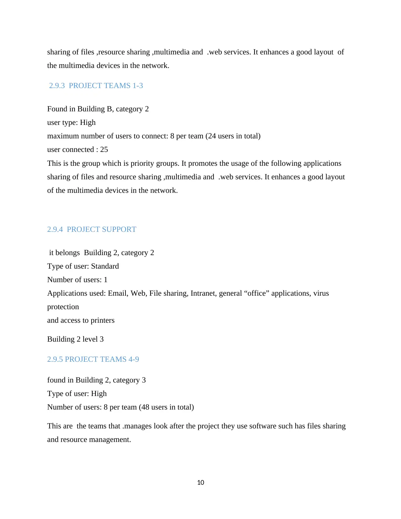
sharing of files ,resource sharing ,multimedia and .web services. It enhances a good layout of
the multimedia devices in the network.
2.9.3 PROJECT TEAMS 1-3
Found in Building B, category 2
user type: High
maximum number of users to connect: 8 per team (24 users in total)
user connected : 25
This is the group which is priority groups. It promotes the usage of the following applications
sharing of files and resource sharing ,multimedia and .web services. It enhances a good layout
of the multimedia devices in the network.
2.9.4 PROJECT SUPPORT
it belongs Building 2, category 2
Type of user: Standard
Number of users: 1
Applications used: Email, Web, File sharing, Intranet, general “office” applications, virus
protection
and access to printers
Building 2 level 3
2.9.5 PROJECT TEAMS 4-9
found in Building 2, category 3
Type of user: High
Number of users: 8 per team (48 users in total)
This are the teams that .manages look after the project they use software such has files sharing
and resource management.
10
Paraphrase This Document
Need a fresh take? Get an instant paraphrase of this document with our AI Paraphraser
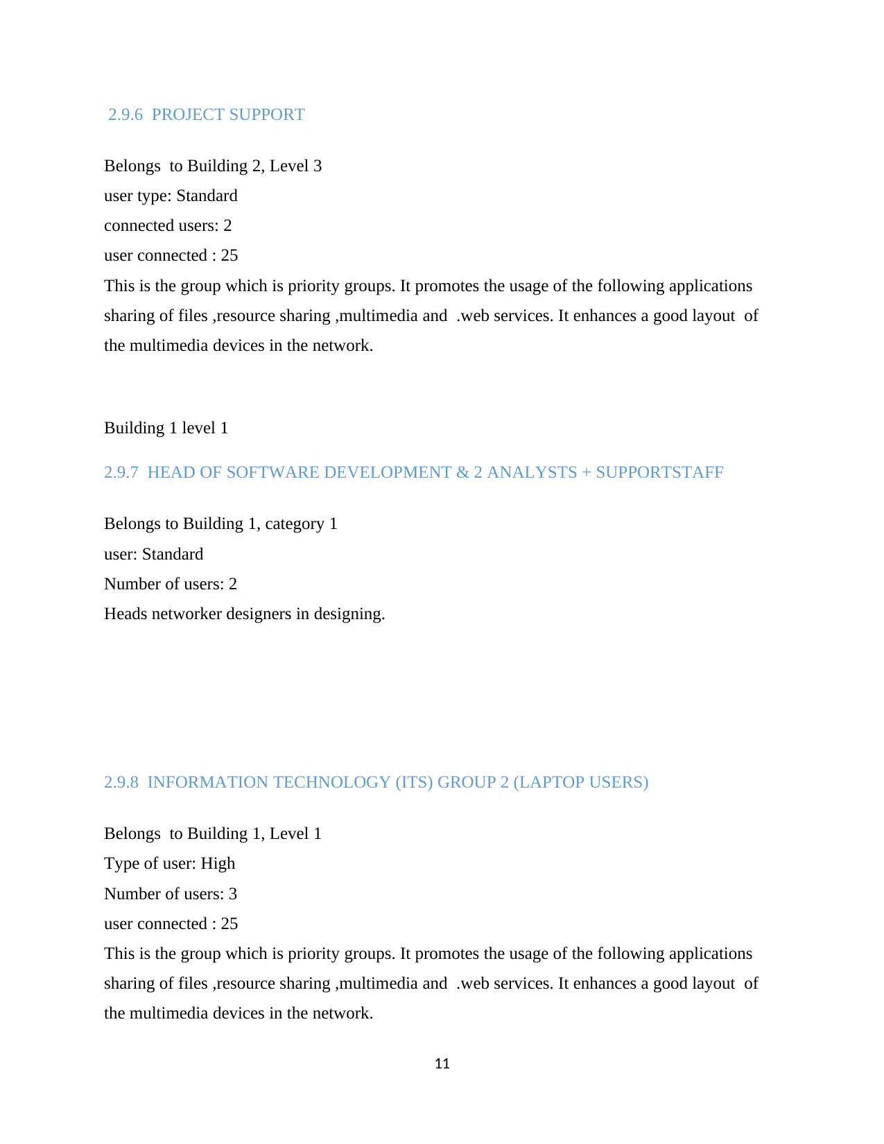
2.9.6 PROJECT SUPPORT
Belongs to Building 2, Level 3
user type: Standard
connected users: 2
user connected : 25
This is the group which is priority groups. It promotes the usage of the following applications
sharing of files ,resource sharing ,multimedia and .web services. It enhances a good layout of
the multimedia devices in the network.
Building 1 level 1
2.9.7 HEAD OF SOFTWARE DEVELOPMENT & 2 ANALYSTS + SUPPORTSTAFF
Belongs to Building 1, category 1
user: Standard
Number of users: 2
Heads networker designers in designing.
2.9.8 INFORMATION TECHNOLOGY (ITS) GROUP 2 (LAPTOP USERS)
Belongs to Building 1, Level 1
Type of user: High
Number of users: 3
user connected : 25
This is the group which is priority groups. It promotes the usage of the following applications
sharing of files ,resource sharing ,multimedia and .web services. It enhances a good layout of
the multimedia devices in the network.
11
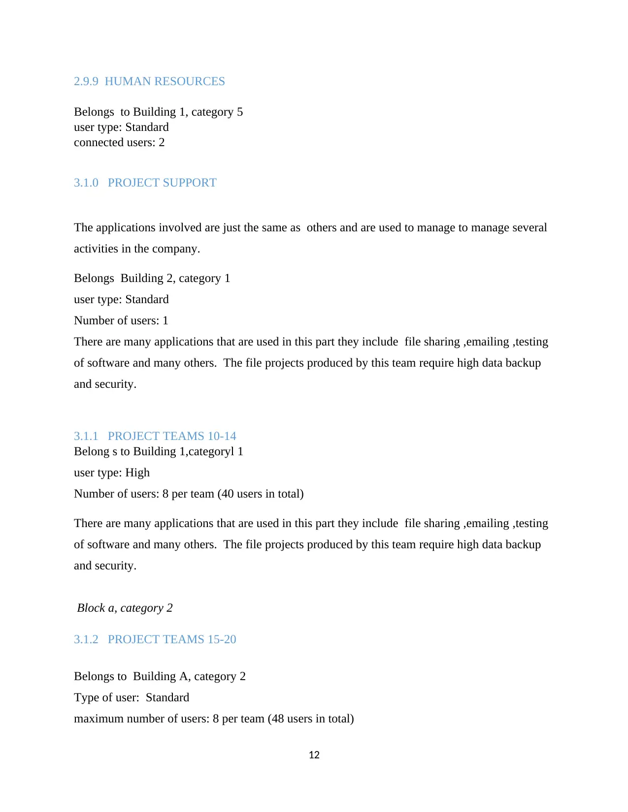
2.9.9 HUMAN RESOURCES
Belongs to Building 1, category 5
user type: Standard
connected users: 2
3.1.0 PROJECT SUPPORT
The applications involved are just the same as others and are used to manage to manage several
activities in the company.
Belongs Building 2, category 1
user type: Standard
Number of users: 1
There are many applications that are used in this part they include file sharing ,emailing ,testing
of software and many others. The file projects produced by this team require high data backup
and security.
3.1.1 PROJECT TEAMS 10-14
Belong s to Building 1,categoryl 1
user type: High
Number of users: 8 per team (40 users in total)
There are many applications that are used in this part they include file sharing ,emailing ,testing
of software and many others. The file projects produced by this team require high data backup
and security.
Block a, category 2
3.1.2 PROJECT TEAMS 15-20
Belongs to Building A, category 2
Type of user: Standard
maximum number of users: 8 per team (48 users in total)
12
⊘ This is a preview!⊘
Do you want full access?
Subscribe today to unlock all pages.

Trusted by 1+ million students worldwide
1 out of 22
Related Documents
Your All-in-One AI-Powered Toolkit for Academic Success.
+13062052269
info@desklib.com
Available 24*7 on WhatsApp / Email
![[object Object]](/_next/static/media/star-bottom.7253800d.svg)
Unlock your academic potential
Copyright © 2020–2026 A2Z Services. All Rights Reserved. Developed and managed by ZUCOL.


