Designing Digital Logic Circuits Using Logisim Simulator
VerifiedAdded on 2021/05/31
|21
|2383
|30
Project
AI Summary
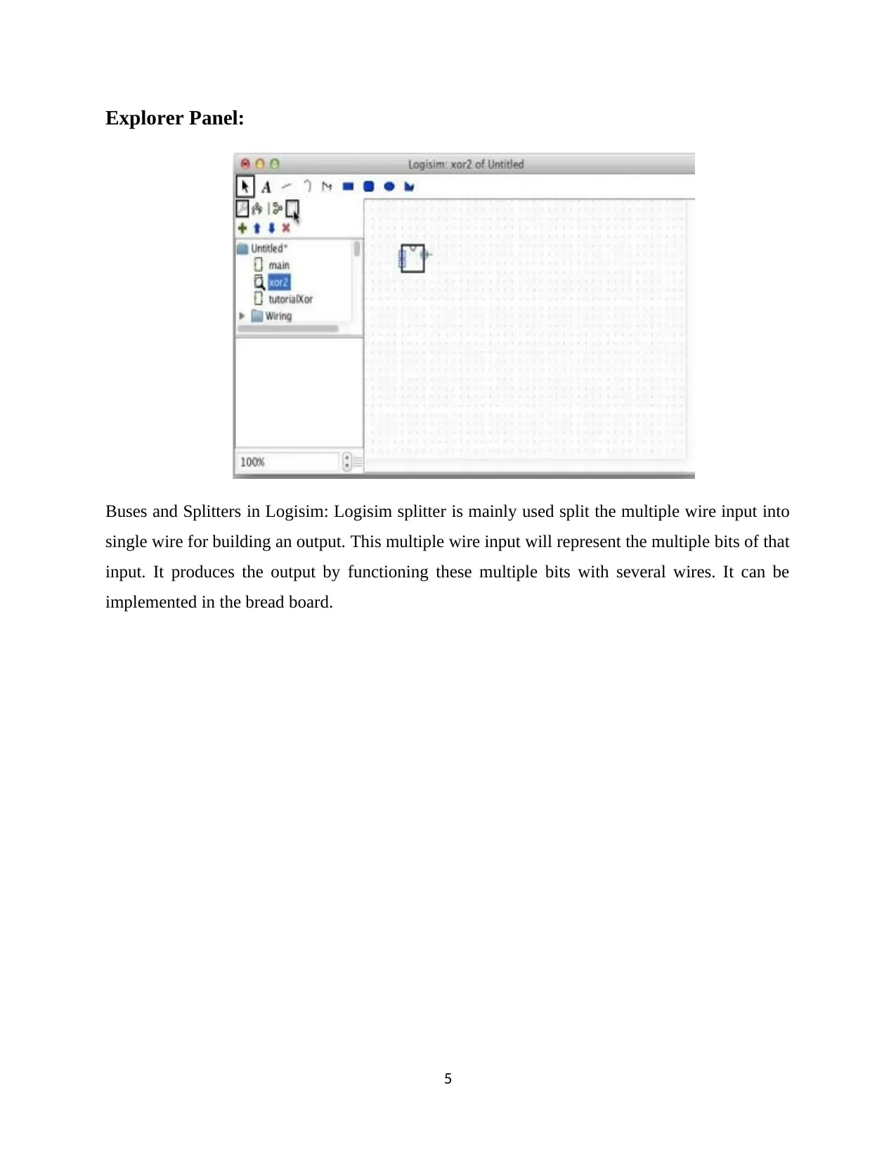
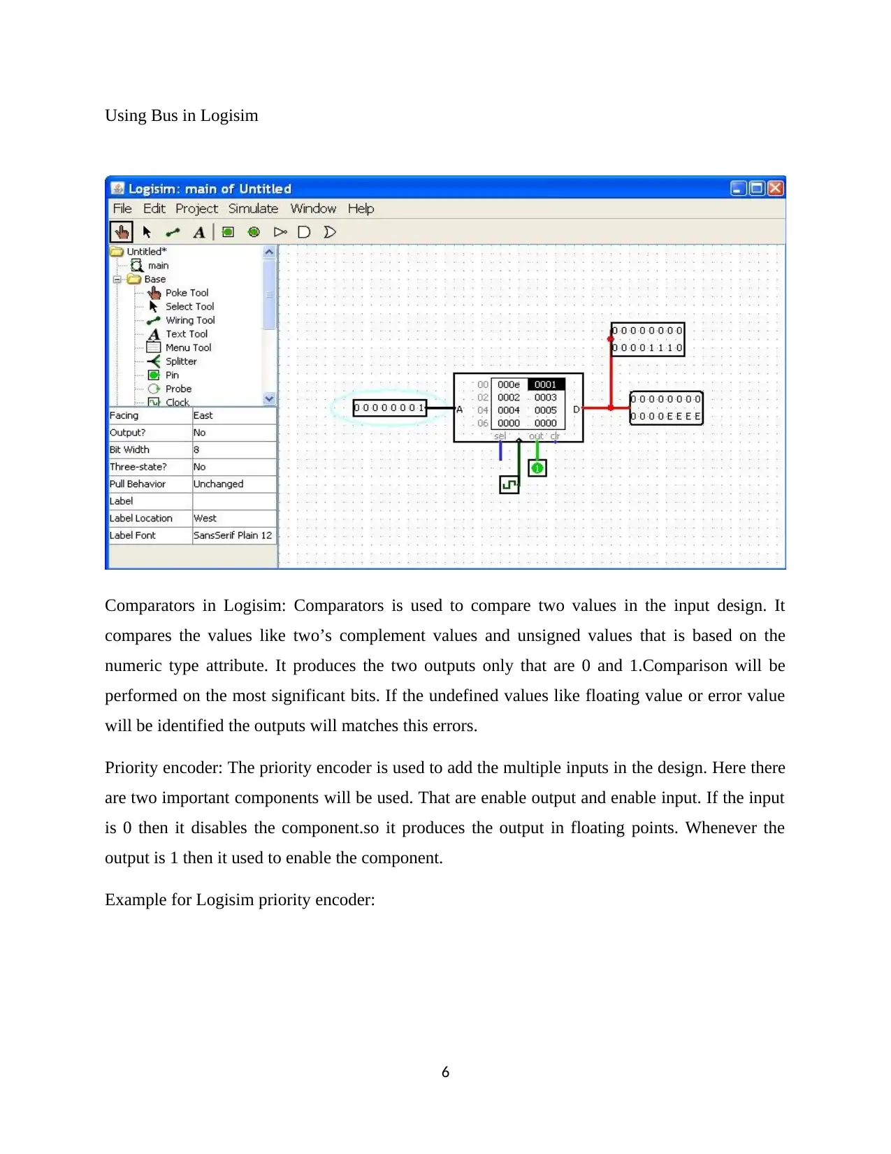
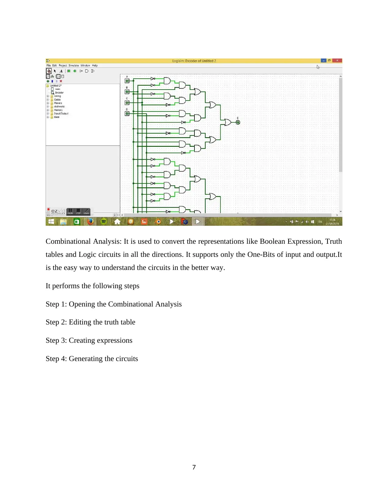
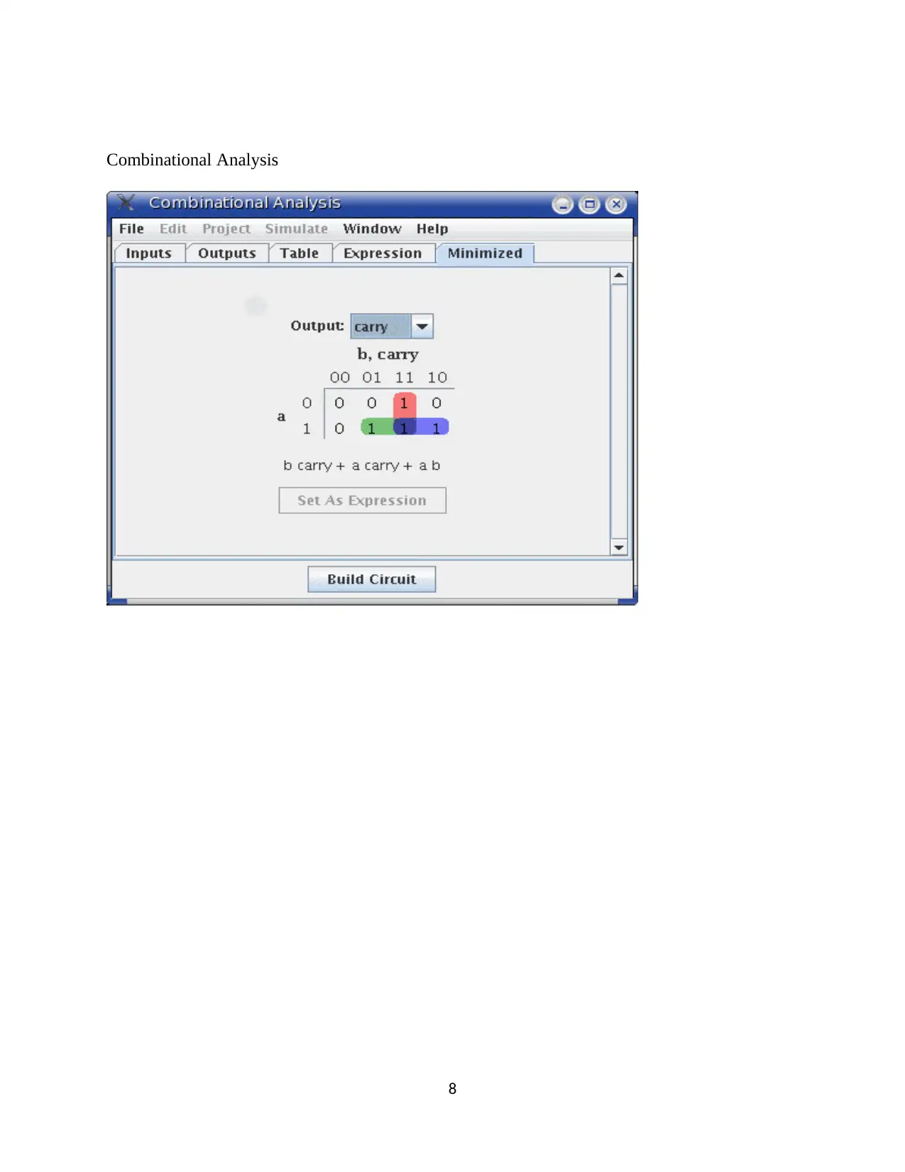
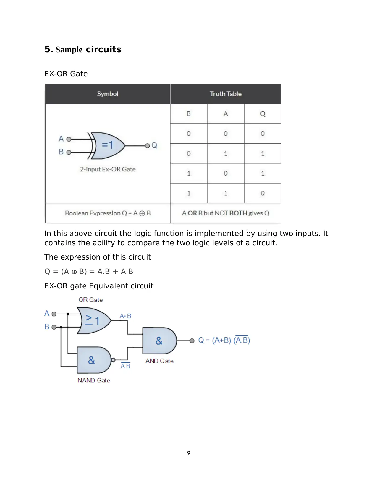
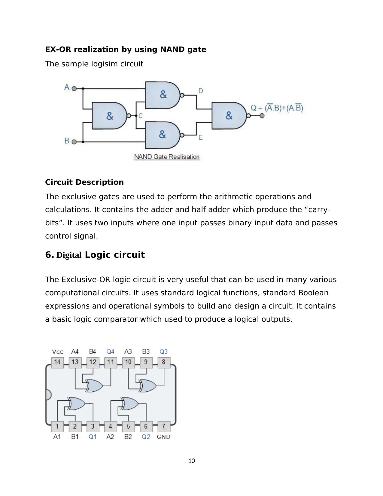
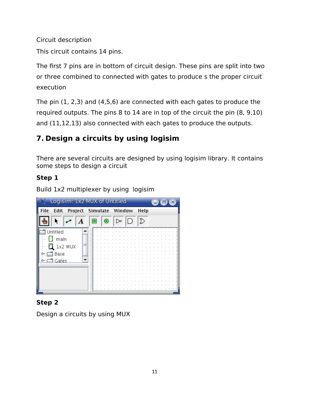
This project details the design and simulation of digital logic circuits using the Logisim simulator. The assignment begins with an introduction to Logisim, its features, and working principles, emphasizing its utility in educational settings for understanding logic circuits. The project covers various aspects, including the use of sub-circuits, buses, splitters, comparators, priority encoders, and combinational analysis. Sample circuits, such as the EX-OR gate and its realization using NAND gates, are presented, along with detailed circuit descriptions. The project also guides the user through the process of designing circuits using Logisim, including the creation of a 1x2 multiplexer and circuit simulation techniques. Different simulation modes, such as simulate enabled, step simulation, and tick simulation, are explained. The project concludes by highlighting the importance of digital logic circuits and the ease of use of Logisim for circuit design and simulation. The document includes references to relevant research papers and resources.

computer systems and networks
Paraphrase This Document
Need a fresh take? Get an instant paraphrase of this document with our AI Paraphraser

Contents
1. Introduction.......................................................................................................................................2
2. Logisim Simulator.............................................................................................................................2
3. Features of an Logisim Simulator....................................................................................................4
4. Working Principles of Logisim.........................................................................................................4
5. Sample circuits.............................................................................................................................10
6. Digital Logic circuit...................................................................................................................11
7. Design a circuits by using logisim................................................................................12
8. Circuit Simulation.....................................................................................................................15
9. Conclusion........................................................................................................................................16
References............................................................................................................................................17
1

1. Introduction
The complete digital logic circuit will be designed by the help of the logisim simulator. There are
multiple software that are used to design a logic circuit. That are available in network at the
commercial and the free manner. But logisim is the efficiently used one. Logisim is a tool that is
used to simulate the circuits called digital logic circuits. It was designed by Carl Burch. It is used
to learn about the logic circuits in detail manner. More than this tool is mainly used to build the
circuits. It is very simple to handle and easy to learn about the circuit designs. To design and
simulate the CPU circuit design for the purpose of educational will be done by the help of the
logisim. It can be used to construct the big circuit from the given small circuits. And it is also
capable to build the bundle of wires with the help of the mouse drag with single action. It is an
application based on java so it has the ability to run in the environments Linux and windows
workstations. Logisim supports the following simulations like Step simulation, Tick simulation,
Simulate enabled. This logisim is used to enable the circuits if it is stateful. This circuit designing
tool will be used in many of the purposes like sophomore-level computer organization uses this
tool for conducting courses. And then it will be used in many of the computer science surveys.
2. Logisim Simulator
Logisim simulator is used to build the digital logic circuit. There are two main purposes for
designing a digital logic circuit. Because it is used to compare the operations of the different
versions in the class. And the second function will be the priority encoder. Logisim is used to
simulate the logic circuits. Here the designs will be simulated with the help of the Graphical User
Interface (GUI).
2
⊘ This is a preview!⊘
Do you want full access?
Subscribe today to unlock all pages.

Trusted by 1+ million students worldwide

Logisim Simulator window
3. Features of an Logisim Simulator
Logisim is an open source software.
This circuit designer will be supported in any platforms like MacOS X, Linux and windows.
It has the wiring tool to build a vertical and horizontal wires.
Here the interface for drawing is based on the tool bar called intuitive toolbar.
Once the circuit will be completed then it can be saved in the file format or print this design into
a printer and it has the ability to export into a GIF file.
To build the large circuit with the help of the sub circuits. Because it is the easy way to build the
circuit.
To perform the operations like Boolean Expressions, Conversion between multiple circuits and
truth tables with the help of Combinational analysis.
3
Paraphrase This Document
Need a fresh take? Get an instant paraphrase of this document with our AI Paraphraser

4. Working Principles of Logisim
Logisim will worked based on the following methods:
Use a sub circuit to build a circuit.
Buses and Splitters in logisim
Comparators
Priority Encoder
Combinational Analysis
Using a Sub circuit: One of the important role for sub circuit is used to build a complex circuits.
This complex circuits in logisim using Sub circuit by the following way,
Choose the Add circuit option in the project menu.
Then name the circuit. This newly created circuit names will be shown under the Explorer panel.
Click the black canvas that is associated with the newly generated circuit.
It shows the small icon for the copy of sub circuits. It can be used to build the circuit multiple
times.
Example for sub circuit: XOR Gate
4

Explorer Panel:
Buses and Splitters in Logisim: Logisim splitter is mainly used split the multiple wire input into
single wire for building an output. This multiple wire input will represent the multiple bits of that
input. It produces the output by functioning these multiple bits with several wires. It can be
implemented in the bread board.
5
⊘ This is a preview!⊘
Do you want full access?
Subscribe today to unlock all pages.

Trusted by 1+ million students worldwide

Using Bus in Logisim
Comparators in Logisim: Comparators is used to compare two values in the input design. It
compares the values like two’s complement values and unsigned values that is based on the
numeric type attribute. It produces the two outputs only that are 0 and 1.Comparison will be
performed on the most significant bits. If the undefined values like floating value or error value
will be identified the outputs will matches this errors.
Priority encoder: The priority encoder is used to add the multiple inputs in the design. Here there
are two important components will be used. That are enable output and enable input. If the input
is 0 then it disables the component.so it produces the output in floating points. Whenever the
output is 1 then it used to enable the component.
Example for Logisim priority encoder:
6
Paraphrase This Document
Need a fresh take? Get an instant paraphrase of this document with our AI Paraphraser

Combinational Analysis: It is used to convert the representations like Boolean Expression, Truth
tables and Logic circuits in all the directions. It supports only the One-Bits of input and output.It
is the easy way to understand the circuits in the better way.
It performs the following steps
Step 1: Opening the Combinational Analysis
Step 2: Editing the truth table
Step 3: Creating expressions
Step 4: Generating the circuits
7

Combinational Analysis
8
8
⊘ This is a preview!⊘
Do you want full access?
Subscribe today to unlock all pages.

Trusted by 1+ million students worldwide

5. Sample circuits
EX-OR Gate
In this above circuit the logic function is implemented by using two inputs. It
contains the ability to compare the two logic levels of a circuit.
The expression of this circuit
Q = (A ⊕ B) = A.B + A.B
EX-OR gate Equivalent circuit
9
EX-OR Gate
In this above circuit the logic function is implemented by using two inputs. It
contains the ability to compare the two logic levels of a circuit.
The expression of this circuit
Q = (A ⊕ B) = A.B + A.B
EX-OR gate Equivalent circuit
9
Paraphrase This Document
Need a fresh take? Get an instant paraphrase of this document with our AI Paraphraser

EX-OR realization by using NAND gate
The sample logisim circuit
Circuit Description
The exclusive gates are used to perform the arithmetic operations and
calculations. It contains the adder and half adder which produce the “carry-
bits”. It uses two inputs where one input passes binary input data and passes
control signal.
6. Digital Logic circuit
The Exclusive-OR logic circuit is very useful that can be used in many various
computational circuits. It uses standard logical functions, standard Boolean
expressions and operational symbols to build and design a circuit. It contains
a basic logic comparator which used to produce a logical outputs.
10

Circuit description
This circuit contains 14 pins.
The first 7 pins are in bottom of circuit design. These pins are split into two
or three combined to connected with gates to produce s the proper circuit
execution
The pin (1, 2,3) and (4,5,6) are connected with each gates to produce the
required outputs. The pins 8 to 14 are in top of the circuit the pin (8, 9,10)
and (11,12,13) also connected with each gates to produce the outputs.
7. Design a circuits by using logisim
There are several circuits are designed by using logisim library. It contains
some steps to design a circuit
Step 1
Build 1x2 multiplexer by using logisim
Step 2
Design a circuits by using MUX
11
⊘ This is a preview!⊘
Do you want full access?
Subscribe today to unlock all pages.

Trusted by 1+ million students worldwide
1 out of 21
Related Documents

Your All-in-One AI-Powered Toolkit for Academic Success.
+13062052269
info@desklib.com
Available 24*7 on WhatsApp / Email
Unlock your academic potential
Copyright © 2020–2025 A2Z Services. All Rights Reserved. Developed and managed by ZUCOL.