Computer Networks: Types, Models, and Security Issues
VerifiedAdded on 2022/09/28
|19
|6395
|45
Report
AI Summary
This report provides a comprehensive overview of computer networks, beginning with classifications based on geographic coverage, interconnection, administration, and architecture. It then delves into various network types, including Personal Area Networks (PANs), Local Area Networks (LANs), Metropolitan Area Networks (MANs), and Wide Area Networks (WANs). The report explores the OSI and Internet models, detailing the functions of each layer, from the physical layer to the application layer. Key concepts such as digital transmission, transmission media (magnetic media, twisted pair, coaxial cable, fiber optics), error detection and correction, flow control, routing protocols (unicast, broadcast, multicast, anycast), and the client-server model are discussed. Finally, the report addresses critical network security issues, including interruption, privacy breaches, integrity, and authenticity, emphasizing the importance of these considerations in modern network environments.
1
Table of Contents
Abstract ......................................................................................................................3
Introduction ............................................................................................................... 4
Computer Network Classification ................................................................................4
Geographic Coverage: .............................................................................................4
Interconnection ....................................................................................................... 5
Administration ........................................................................................................5
Architecture ............................................................................................................5
Computer Network Types ........................................................................................... 5
A. Personal Area Network (PAN) .............................................................................5
B. Local Area Network (LAN) ..................................................................................6
C. Network of Metropolitan Area (MAN) .................................................................6
D. Wide Area Networking (WAN) ............................................................................6
Computer Network Models ......................................................................................... 7
A. OSI Model .......................................................................................................... 7
B. Internet Model ....................................................................................................7
Physical Layer ............................................................................................................ 8
A. Digital Transmission ........................................................................................... 8
B. Transmission Media ............................................................................................9
Magnetic Media ...................................................................................................9
Twisted Pair Cables ........................................................................................... 10
Coaxial Cable .................................................................................................... 10
Power Lines .......................................................................................................10
Fiber Optics .......................................................................................................11
Data Link Layer ....................................................................................................... 11
A. Error Detection and Correction .........................................................................12
Detecting Errors ................................................................................................ 12
REDUNDANCY CHECK ON A CYCLIC BASIS (CRC) .................................... 12
Data Link Control and Protocols ............................................................................... 13
A. Flow Control .....................................................................................................13
Stop and Wait ....................................................................................................13
ARQ Selective Repetition ................................................................................... 14
Paraphrase This Document
Need a fresh take? Get an instant paraphrase of this document with our AI Paraphraser
2
Network Layer ..........................................................................................................14
A. Unicast Routing ................................................................................................ 14
B. Broadcasts Routing ........................................................................................... 15
C. Multicast Routing ............................................................................................. 15
D. Anycast Routing ................................................................................................15
Transport Layer ....................................................................................................... 16
Transmission Control Protocol............................................................................... 16
Application Layer ..................................................................................................... 16
A. Client Server Model .......................................................................................... 16
Socket ................................................................................................................... 17
Remote Procedure Call (RPC) ............................................................................... 17
Network Security Issues ............................................................................................ 17
A. Interruption ......................................................................................................18
B. Privacy Breach ..................................................................................................18
C. Integrity............................................................................................................ 18
D. Authenticity ...................................................................................................... 18
Applications ..............................................................................................................18
References ................................................................................................................ 19
3
Abstract
Computer networks, also called data networks, are types of telecommunications
networks that allow computers to communicate with each other. Computer networks
use data links to carry data between networked devices. A network link is established
between nodes using either cable or wireless media. One of the world's most popular
networks is the Internet. A network node originates, transports, and terminates data on
a network. The node can be a computer, a phone, a server, or networking equipment.
Networking means sharing information between devices, regardless of whether they
are connected directly. Networks enable access to the World Wide Web, the use of
shared application and storage servers, printers, and fax machines, as well as the use
of email and instant messaging applications. Each computer network has its own
characteristics, from the physical media it uses to carry signals to its topology and
scale, as well as its organizational intent.
Keywords: Computer Networks, Network Classifications, Local Area Network,
Coaxial Cables, Network Security, Physical Layer
⊘ This is a preview!⊘
Do you want full access?
Subscribe today to unlock all pages.
Trusted by 1+ million students worldwide
4
Introduction
A computer network is a linked collection of computers and computerized
peripherals such as printers. This connectivity makes it easier for computers to
communicate information. Computers can connect with each other via either wired or
wireless media. Networking engineering involves the use of software, firmware, chip
level engineering, hardware, and electric pulses. To make network engineering easier,
the entire networking idea is separated into numerous levels. Each layer is in charge
of a distinct task and is independent of the others. However, practically all networking
operations rely in some manner on all of these levels.
The internet is a network that is made up of other networks. It is the biggest
network of any type in the world. The internet connects all WANs, which can also
link to LANs and residential networks. The Internet's protocol suite is TCP/IP, and IP
is its addressing protocol. IPv4 is widely utilized on the Internet in today's globe. Due
to a lack of address spaces, it is progressively moving from IPv4 to IPv6. The Internet
enables people to exchange and access vast amounts of information from across the
world. It involves use of the WebPages, FTP, email accounts, audio and video
streams, and other similar technologies. On a broad scale, the internet runs on Client-
Server architecture. Fiber optics offers an extremely fast backbone for networks.
Computer Network Classification
A computer network is a linked group of computers and computerized peripherals
such as printers. This connectivity makes it easier for computers to communicate
information. Computers can connect with each other via either wired or wireless
media. Computer networks are classified based on a variety of features. These are:
Geographic coverage, interconnection, administration, and architecture.
Geographic Coverage:
Based on its location, a network can be categorized into one of the following
categories. It can link Bluetooth-enabled devices across your desktop. There are
barely a few yards between them. It might be put throughout the structure, with
Paraphrase This Document
Need a fresh take? Get an instant paraphrase of this document with our AI Paraphraser
5
intermediary devices linking all floors. It has the potential to blanket a whole city. It
might be dispersed throughout numerous cities or provinces. It might be a single
network that spans the globe.
Interconnection
The components of a network can be linked in a number of ways. Every device on the
network may communicate with every other device on the network, resulting in the
formation of a network mesh. All devices can be linked to a single medium, although
it is a geographically dispersed bus-like system. Because each gadget is only
connected to its peers on the left and right sides, the structure is linear. All of the
devices were linked together by a single device, making a star-like structure. All
devices were hastily linked using all prior approaches, resulting in a hybrid structure.
Administration
According to an administrator, a network can be a private network belonging to an
autonomous system and cannot be accessed outside the system's physical boundaries
or logical domain. Networks can also be accessible by the public.
Architecture
A computer network can be categorized as Client-Server, Peer-to-Peer, or Hybrid
based on its architecture. The server might be one or multiple systems. On the other
side, the User requests that the Server serve requests. The server accepts and
processes client requests.
Computer Network Types
A. Personal Area Network (PAN)
A Personal Area Network (PAN) is the most basic network that an individual may
connect to. Bluetooth-enabled or infrared-enabled devices will be included in this
category. PAN has a connection range of 10 meters. PAN can be found in wireless
computer keyboards and mouse, Bluetooth-enabled headphones, wireless printers, and
TV remotes. Pico net is a Bluetooth-enabled Personal Area Network that can link up
to eight devices in a master-slave configuration.
6
B. Local Area Network (LAN)
A "local area network" is a computer network that covers a complete building and is
controlled by a single administration system (LAN). A company's LAN often
encompasses its offices, schools, colleges, and institutions. The number of systems
linked in a LAN might range from two to sixteen million. A local area network (LAN)
is a convenient way for end users to exchange resources. Printers, file servers,
scanners, and the internet may all be shared simply across machines.
Local area networks (LANs) are built with low-cost networking and routing devices.
There may be local servers that offer file storage and other locally shared applications.
It mostly use private IP addresses and does not make extensive use of routing. LANs
operate under their own local domains and are administered from a central location.
C. Network of Metropolitan Area (MAN)
The Metropolitan Area Network (MAN) is a sort of cable television network that
covers a large area. Some of the alternatives are Ethernet, Token-ring, ATM, and
Fiber Distributed Data Interface (FDDI). Metro Ethernet is a service that Internet
service providers provide (ISPs). This service allows users to expand their Local Area
Networks. MAN, for example, may let a corporation link all of its offices around a
city. The backbone of MAN is high-capacity, high-speed fiber optics. The MAN
connects the local area network to the wide area network. MAN links local area
networks (LANs) to wide area networks (WANs) or the internet.
D. Wide Area Networking (WAN)
As the name indicates, a Wide Area Network (WAN) covers a broad area that may
cover provinces or perhaps the whole country. Telecommunications networks are
frequently Wide Area Networks. These networks link together MANs and LANs.
Because they have a highly fast backbone, WANs require relatively costly network
equipment. Advanced WAN technologies include Asynchronous Transfer Mode
(ATM), Frame Relay, and Synchronous Optical Network (SONET). The WAN may
be overseen by many authorities.
⊘ This is a preview!⊘
Do you want full access?
Subscribe today to unlock all pages.
Trusted by 1+ million students worldwide
7
Computer Network Models
A. OSI Model
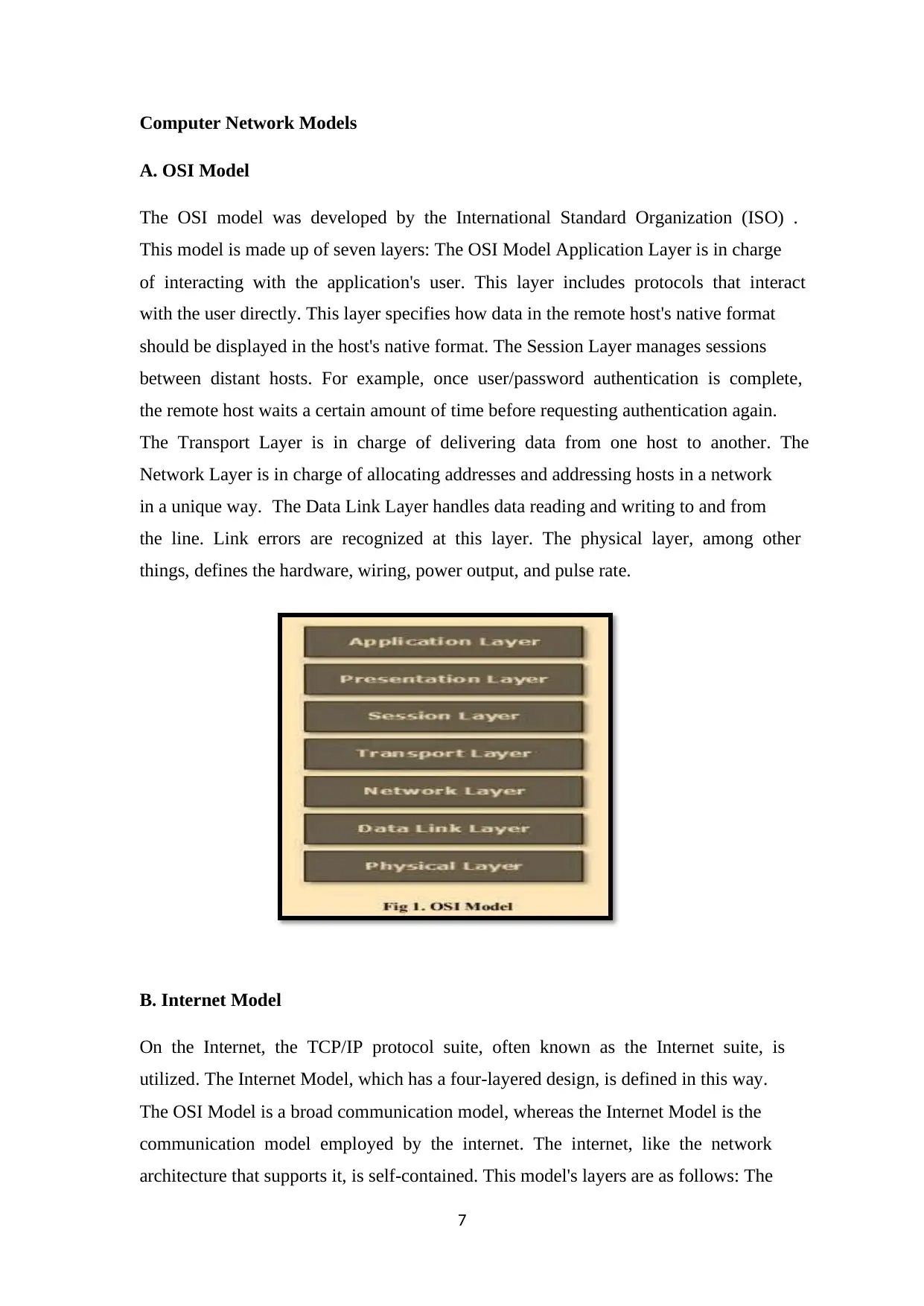
The OSI model was developed by the International Standard Organization (ISO) .
This model is made up of seven layers: The OSI Model Application Layer is in charge
of interacting with the application's user. This layer includes protocols that interact
with the user directly. This layer specifies how data in the remote host's native format
should be displayed in the host's native format. The Session Layer manages sessions
between distant hosts. For example, once user/password authentication is complete,
the remote host waits a certain amount of time before requesting authentication again.
The Transport Layer is in charge of delivering data from one host to another. The
Network Layer is in charge of allocating addresses and addressing hosts in a network
in a unique way. The Data Link Layer handles data reading and writing to and from
the line. Link errors are recognized at this layer. The physical layer, among other
things, defines the hardware, wiring, power output, and pulse rate.
B. Internet Model
On the Internet, the TCP/IP protocol suite, often known as the Internet suite, is
utilized. The Internet Model, which has a four-layered design, is defined in this way.
The OSI Model is a broad communication model, whereas the Internet Model is the
communication model employed by the internet. The internet, like the network
architecture that supports it, is self-contained. This model's layers are as follows: The
Computer Network Models
A. OSI Model
The OSI model was developed by the International Standard Organization (ISO) .
This model is made up of seven layers: The OSI Model Application Layer is in charge
of interacting with the application's user. This layer includes protocols that interact
with the user directly. This layer specifies how data in the remote host's native format
should be displayed in the host's native format. The Session Layer manages sessions
between distant hosts. For example, once user/password authentication is complete,
the remote host waits a certain amount of time before requesting authentication again.
The Transport Layer is in charge of delivering data from one host to another. The
Network Layer is in charge of allocating addresses and addressing hosts in a network
in a unique way. The Data Link Layer handles data reading and writing to and from
the line. Link errors are recognized at this layer. The physical layer, among other
things, defines the hardware, wiring, power output, and pulse rate.
B. Internet Model
On the Internet, the TCP/IP protocol suite, often known as the Internet suite, is
utilized. The Internet Model, which has a four-layered design, is defined in this way.
The OSI Model is a broad communication model, whereas the Internet Model is the
communication model employed by the internet. The internet, like the network
architecture that supports it, is self-contained. This model's layers are as follows: The
Paraphrase This Document
Need a fresh take? Get an instant paraphrase of this document with our AI Paraphraser
8
Internet Model Application Layer defines the protocol that allows users to interact
with the network. Examples include FTP, HTTP, and other protocols. This layer
establishes the protocol for data transport between hosts. At this layer, the
Transmission Control Protocol is the most significant protocol (TCP). This layer is in
charge of end-to-end delivery and guarantees that data is sent in the right sequence
between hosts. The Internet Protocol (IP) is implemented at this layer. This layer
simplifies the process of addressing and recognizing hosts. The Link Layer is in
charge of transmitting and receiving data. Unlike its OSI Model counterpart, this layer
is not affected by the underlying network architecture or hardware.
Physical Layer
The physical layer interacts with actual hardware and signaling systems in the OSI
model. The OSI network model's physical layer is the only one that deals with the
physical connection between two stations. This layer, among other things, defines the
hardware, cabling, wiring, frequencies, and pulses required to represent binary
signals.
The Physical layer provides services to the Data-link layer. The data link layer sends
frames to the physical layer. The physical layer converts them to electrical pulses,
which represent binary data. The binary data is then transferred over wired or wireless
media.
The two approaches for storing data or information are analog and digital storage. For
a computer to use the data, it must be in a distinct digital format. Signals, like data,
can be analog or digital in nature. Before data can be delivered digitally, it must first
be converted to digital form.
A. Digital Transmission
Line coding and block coding are the two ways for converting digital data into digital
signals. All communications must use line coding, but block coding is optional.
The technique of converting digital data into digital signals is known as line coding.
The most frequent type of digital data is binary data. It's represented (stored)
internally as a series of 1s and 0s. A digital signal is defined as a discrete signal that
represents digital data. Line coding techniques are divided into three categories.
9
Unipolar encoding techniques use a single voltage level to encode data. High voltage
is given to represent binary 1 in this case, whereas no voltage is sent to represent
binary 0. It's also known as Unipolar Non-return-to-zero since there's no rest
condition. It represent either 1 or 0.
Polar Encoding is a type of coding that is used to encode data. In the polar encoding
approach, binary information is represented by several voltage levels. Polar encodings
may be divided into four categories: Non-Return to Zero in the Polar Regions (Polar
NRZ) is a binary value representation that uses two voltage levels. Positive voltage
equals 1 in general, while negative voltage equals 0. Due to the lack of a rest period, it
is also NRZ. NRZ-L and NRZ-I are the two sections of the NRZ system.
NRZ-L changes voltage level when a different bit is detected, while NRZ-I changes
voltage when a 1 is discovered in NRZ Unipolar. The issue with NRZ is that if the
sender and receiver clocks aren't in sync, the receiver won't be able to tell when one
bit ended and the next one began. Return to the beginning (RZ) The term "return-to-
zero" refers to the process of going back to zero. Positive voltage denotes one,
negative voltage denotes zero, and zero voltage indicates none. Signals change in
between bits, not in the middle of them. When RZ and NRZ-L are coupled in this
encoding scheme, it is known as the Manchester case. A bit's duration is divided into
two parts. It changes phase and transits in the middle of the bit when a different bit
meets it.
B. Transmission Media
The transmission media in computer networks are the physical means via which
communication takes place.
Magnetic Media
Even before networking, one of the most practical methods of transferring data from
one computer to another was to store it on storage media and physically transfer it
from one station to another. Magnetic media, however it may appear outdated in
today's age of high-speed internet, comes into play when the volume of data is vast. In
these cases, data backup is recorded on magnetic tapes or magnetic discs and then
physically relocated to remote locations.
⊘ This is a preview!⊘
Do you want full access?
Subscribe today to unlock all pages.
Trusted by 1+ million students worldwide
11
Twisted Pair Cables
Twisted pair cables are made up of two plastic-insulated copper wires that are twisted
together to form a single medium. Only one of these two cables sends an actual
signal, while the other acts as a ground reference. Twisting wires together can
minimize noise (electromagnetic interference) and crosstalk. Twisted pair cables are
classified into two types: Cable STP (Shielded Twisted Pair) UTP (Unshielded
Twisted Pair) cable is a type of unprotected cable.
In STP cables, the twisted wire pair is coated in metal foil. As a result, it's less
sensitive to noise and crosstalk. UTP is separated into seven categories, each having a
unique range of uses. In computer networks, Cat-5, Cat-5e, and Cat-6 cables are often
used. UTP cables are connected using RJ45 connections.
Coaxial Cable
Coaxial cable is made of copper wires. The core wire, which is made of solid
conductor, is in the center. The core is surrounded by an insulating layer. The second
wire is wrapped around the sheath and then around the insulator sheath. A plastic
cover protects everything. Because of its structure, coax cable can transport higher
frequency signals than twisted pair cable. Because of the wrapped structure, it boasts
outstanding noise and cross talk prevention. Coaxial cables may give bandwidth of up
to 450 mbps. Coax cables are classified into three types: RG-59 (Cable TV), RG-58
(Thin Ethernet), and RG-11 (Thick Ethernet). The abbreviation for Radio Government
is RG. To connect the cables, the BNC connector and BNC-T are utilized. The wire is
terminated at both ends with a BNC terminator.
Power Lines
Power line communication is a Layer-1 (Physical Layer) technique that uses power
lines to transport data messages (PLC). Modulated data is transferred via a PLC's
cables. Because power lines are widely utilized, the data is de-modulated and
processed by the receiver on the other end. A PLC may manage and monitor any
powered devices. The PLC is set to operate in half-duplex mode. PLCs are classified
into two types: programmable logic controllers (PLCs) and programmable PLCs with
narrow band. PLC with a broad frequency range Narrow band PLCs provide reduced
data rates of up to 100s of kbps since they operate at lower frequencies (3-5000 kHz).
Paraphrase This Document
Need a fresh take? Get an instant paraphrase of this document with our AI Paraphraser
11
They may be found over a wide range of distances. Broadband PLC runs at higher
frequencies (1.8–250 MHz) and provides data speeds of up to 100s of Mbps. They
cannot be expanded as far as Narrowband PLC.
Fiber Optics
Fiber Optics is a type of optical fiber that is used in communications. Fiber Optics is
based on the properties of light. A light beam refracts at a 90-degree angle when it
encounters a critical angle. This property has been exploited in fiber optics. The core
of a fiber optic cable is made of high-quality glass or plastic. Light is emitted from
one end, travels through it, and is detected and converted to electric data by a light
detector at the other end.
Fiber optics is the most efficient mode of transmission. It comes in two varieties:
single mode fiber and multimode fiber. A single mode fiber can only carry one light
ray, but a multimode fiber can carry several beams.
Data Link Layer
The second layer of the OSI Layered Model is the Data Link Layer. This layer is one
of the most difficult to perceive, since it has a variety of functions and threats.
The data connection layer hides the underlying hardware characteristics and presents
itself as a communication channel to the higher layer. The data connection layer joins
two hosts that are directly linked in some way. This direct connection can be either
point-to-point or broadcast. Systems on a broadcast network are said to be on the
same connection. The data connection layer's duty gets more difficult when dealing
with several hosts on a single collision domain.
The data connection layer is in responsible of converting data streams to signals bit by
bit and delivering them across the underlying hardware. The Data Link Layer takes
data from hardware as electrical impulses, assembles it into a recognized frame
format, and transfers it on to the higher layer. The data connection layer is divided
into two sub-layers: logical link control, which covers protocols, flow control, and
error control. The real management of media is handled by Media Access Control.
12
A. Error Detection and Correction
Data can be corrupted during transmission due to a number of factors such as noise,
cross-talk, and so on. Upper layers are unaware of real hardware data processing and
rely on a fictitious representation of network architecture. As a result, higher levels
expect flawless system communication. The majority of programs will not function
properly if they get inaccurate data. Voice and video apps may not be as affected as
other programs, and even if they are, they may still function well. The data-link layer
includes several error control algorithms to ensure that frames (data bit streams) are
transmitted with a certain degree of correctness. However, in order to understand how
mistakes are controlled, it is vital to first understand the many types of errors that
might occur.
Detecting Errors
To detect errors in received frames, the Parity Check and Cyclic Redundancy Check
are utilized (CRC). In both cases, a few extra bits are sent in addition to the actual
data to guarantee that the bits received at the other end match the ones sent. If the
counter check at the receiver fails, the bits are considered corrupted.
When even parity is used, an additional bit is broadcast together with the original bits
to make the number of 1s even, and when odd parity is used, an additional bit is
transmitted along with the original bits to make the number of 1s odd. As a frame is
formed, the sender counts the number of 1s in it. When using even parity and the
number of ones is even, for example, one bit with the value 0 is added. In this way,
the number of 1s will remain constant. If the number of 1s is odd, a value of 1 is
added to even things out.
REDUNDANCY CHECK ON A CYCLIC BASIS (CRC)
CRC is another mechanism for detecting whether or not the data in the received frame
is genuine. This approach employs binary division of the data bits being transferred.
The divisor is created using polynomials. The transmitter divides the bits being
communicated and computes the remainder. Before transferring the remaining bits,
the sender adds them to the end of the genuine bits. A codeword is a group of data bits
plus the remainder. The transmitter sends data bits in code words.
⊘ This is a preview!⊘
Do you want full access?
Subscribe today to unlock all pages.
Trusted by 1+ million students worldwide
1 out of 19
Related Documents


Your All-in-One AI-Powered Toolkit for Academic Success.
+13062052269
info@desklib.com
Available 24*7 on WhatsApp / Email
![[object Object]](/_next/static/media/star-bottom.7253800d.svg)
Unlock your academic potential
Copyright © 2020–2026 A2Z Services. All Rights Reserved. Developed and managed by ZUCOL.