BTEC HND in Computing & System Development: Systems Architecture
VerifiedAdded on 2021/05/20
|52
|8083
|1763
Homework Assignment
AI Summary
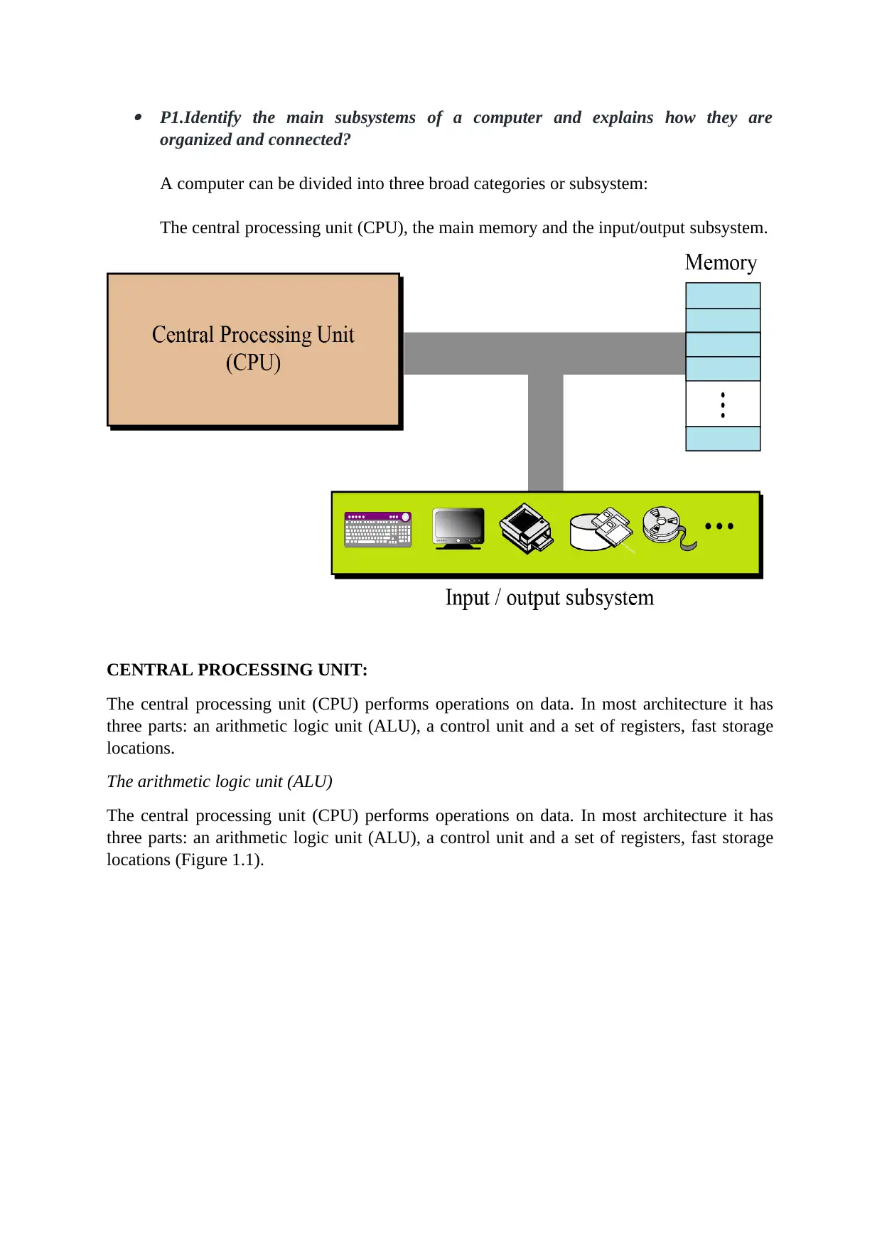
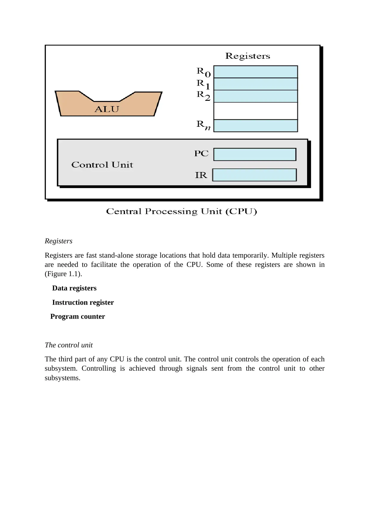
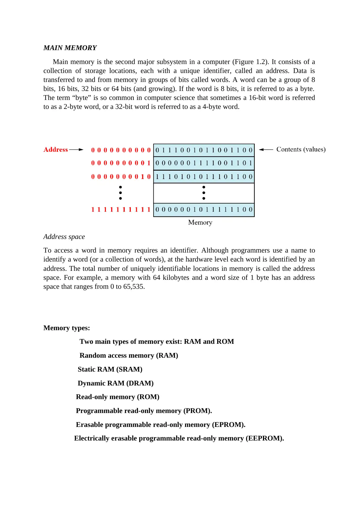
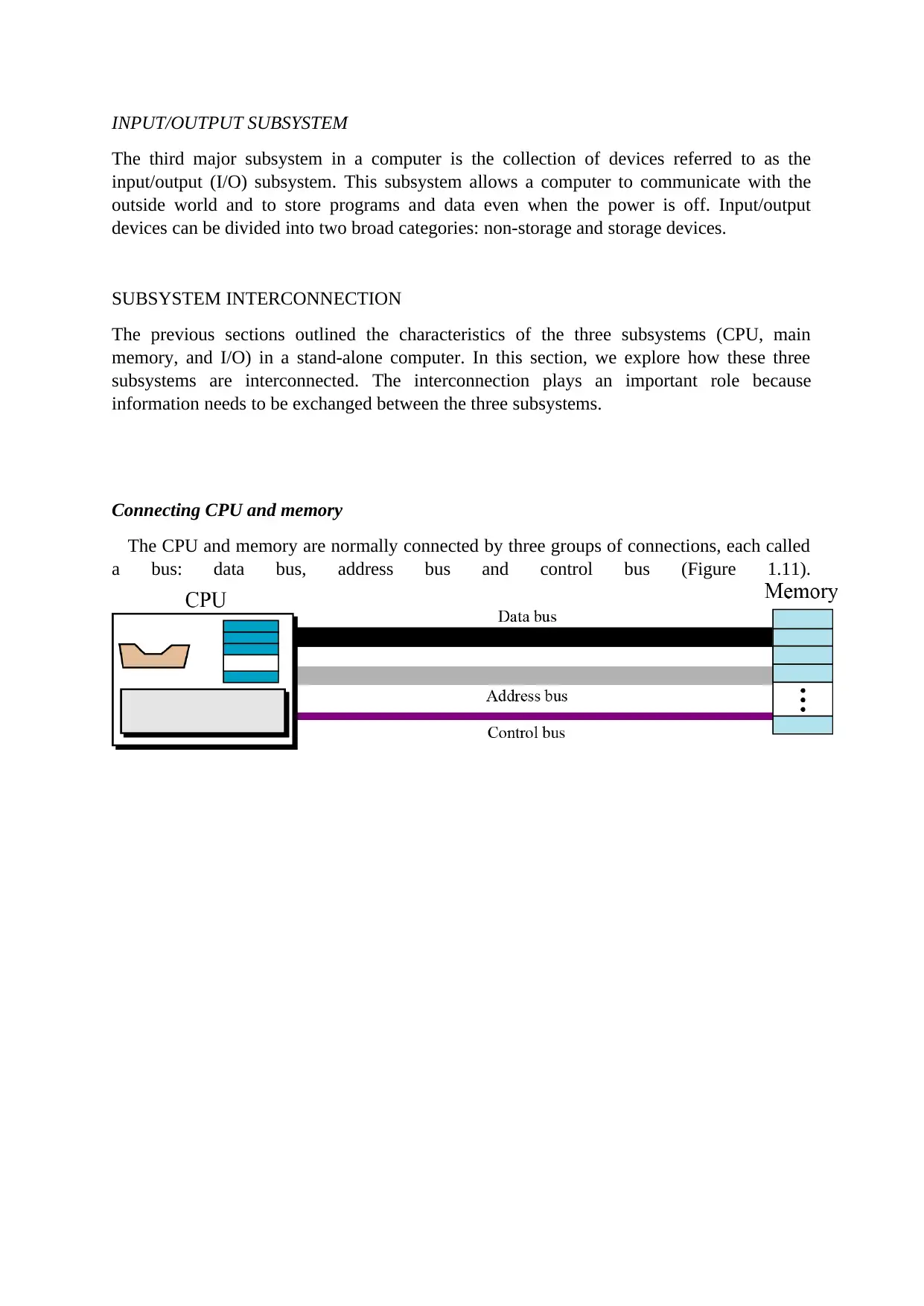
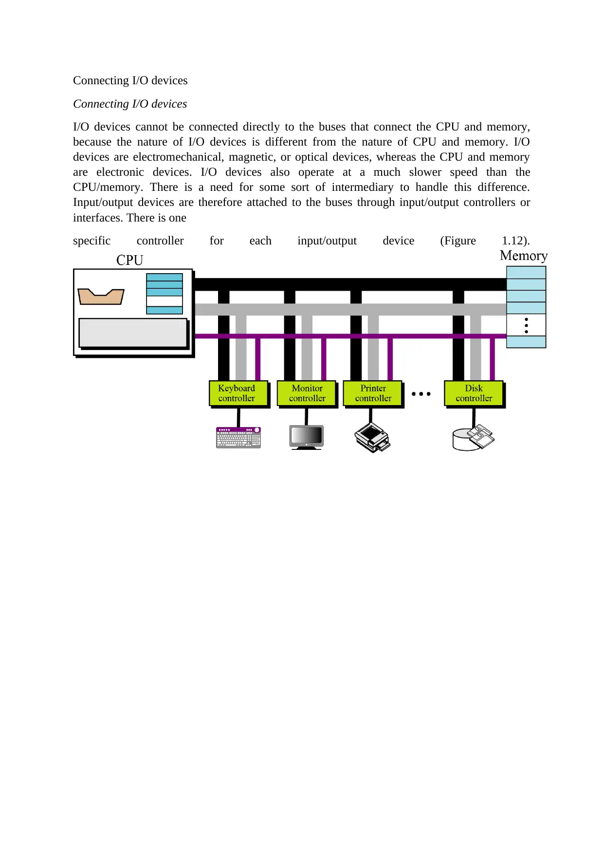
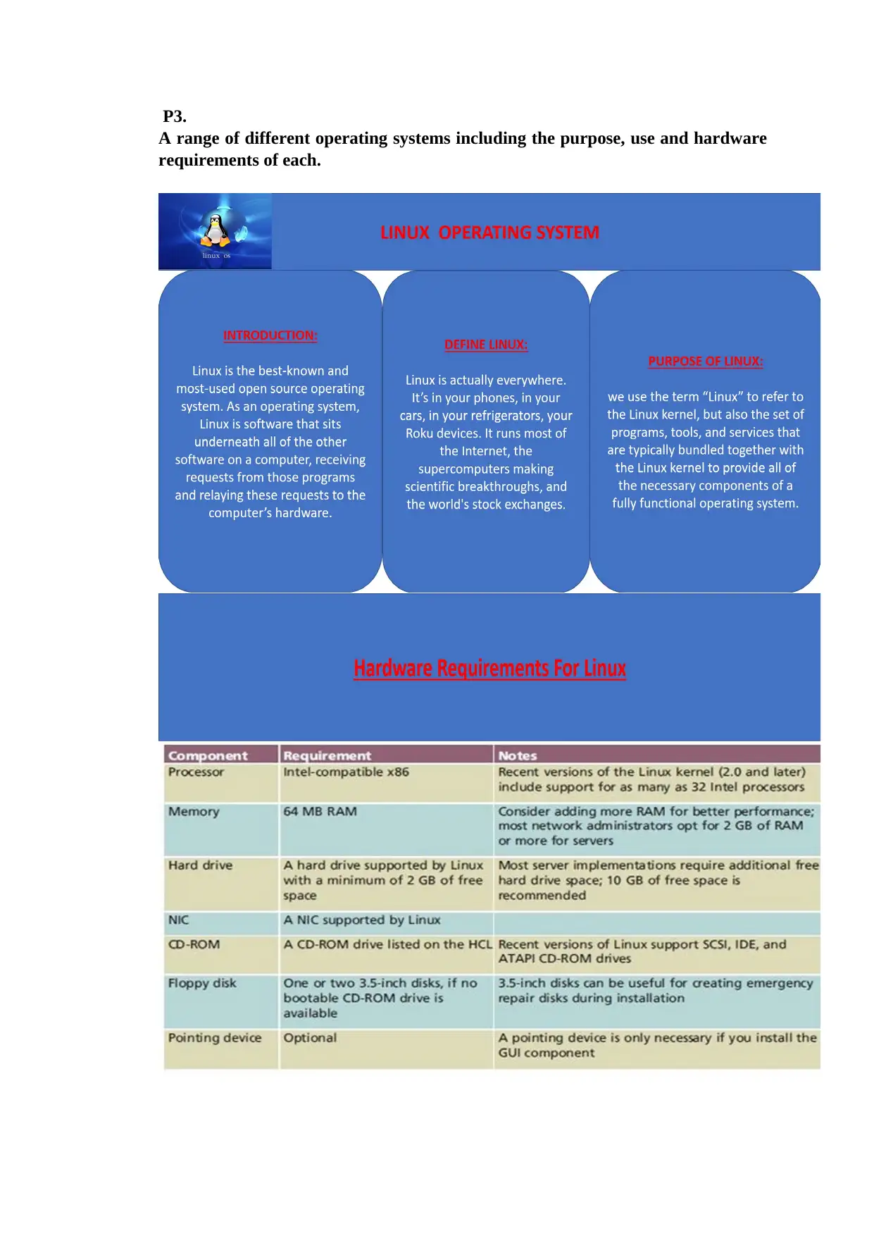
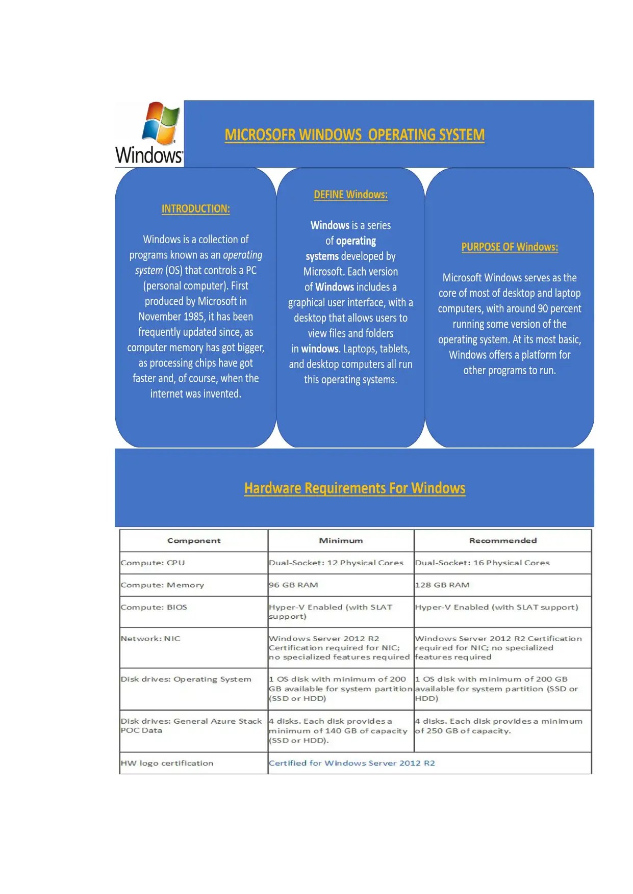
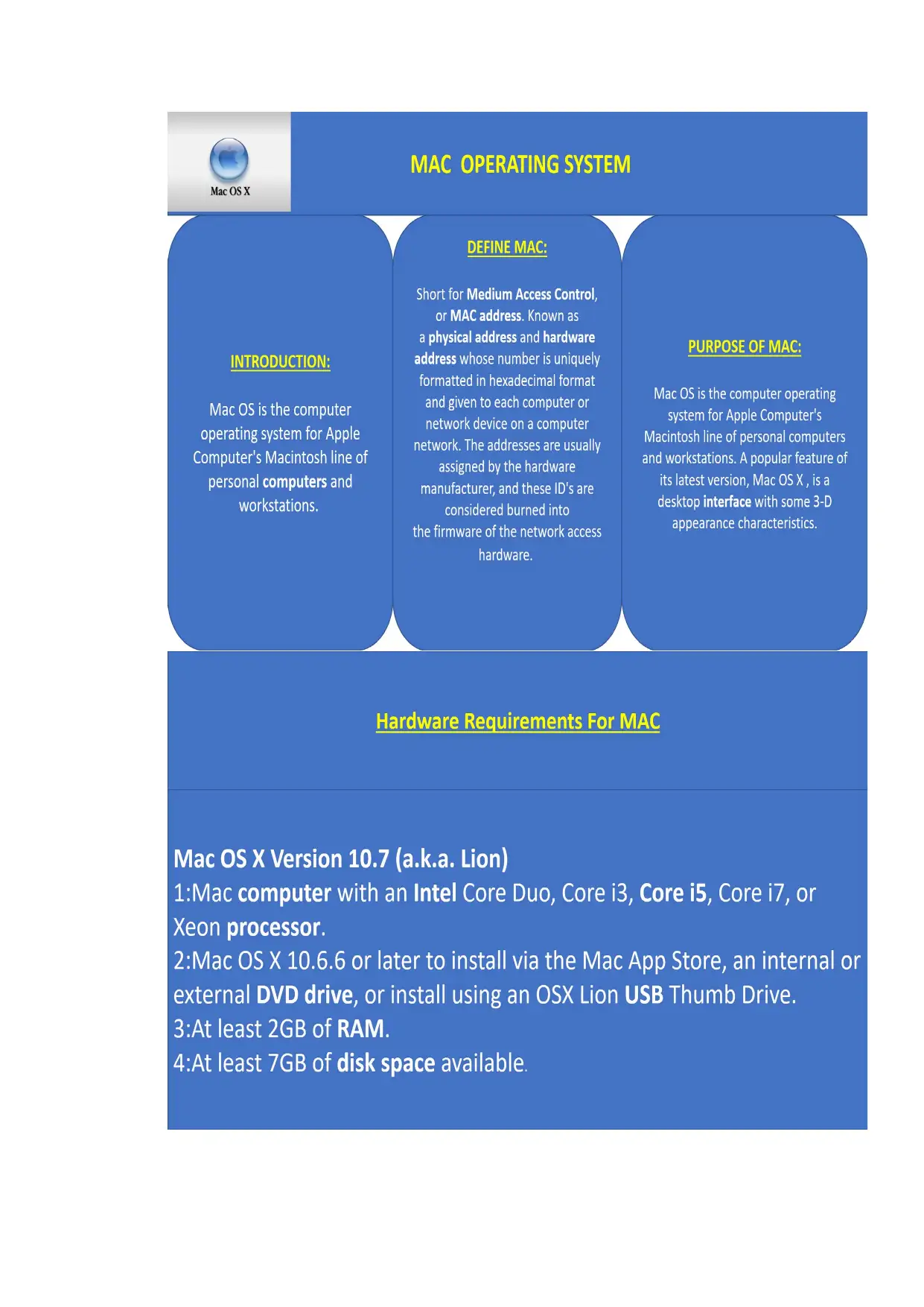
This assignment on Computer Systems Architecture provides a detailed exploration of computer systems, starting with an introduction to hardware and software components. It identifies and explains the main subsystems of a computer, including the CPU, main memory, and input/output subsystem, detailing their organization and interconnections. The assignment also examines the purpose and operation of the CPU, assessing its dependency and performance concerning associated systems and subsystems, considering factors like clock rate, calculation units, cache size, bus protocols, and sub-architecture design. Furthermore, it covers various operating systems, their purposes, uses, and hardware requirements, along with the architecture of operating systems like Linux, Windows, and Mac OS X. The assignment also explains the relationships between hardware and network addresses, including their use with regards to networking devices and components, and compares common physical and logical networking topologies, explaining their differences and purposes. Finally, it evaluates the OSI and TCP/IP models concerning hierarchy, layers, and services, including information on associated protocols and hardware, providing a comprehensive understanding of computer systems and networking.
Contribute Materials
Your contribution can guide someone’s learning journey. Share your
documents today.

UKCBC Computer Systems Architecture
Name of the student: MD.ABU SAYAD SAZZAD
Course: BTEC HND in COMPUTING & SYSTEM DEVELOPMENT
Student ID No: 17000101
Campus: WENTWORTH HOUSE
Name of the Module: Computer Systems Architecture
Introduce a computer system.
A computer is a complex system consisting of both hardware and software
components.
The Hardware:
Secure Best Marks with AI Grader
Need help grading? Try our AI Grader for instant feedback on your assignments.

The hardware is the machinery itself. It is made up of the physical parts or devices of
the computer system like the electronic Integrated Circuits (ICs), magnetic storage
media and other mechanical devices like input devices, output devices etc. All these
various hardware are linked together to form an effective functional unit. The various
types of hardware used in the computers, has evolved from vacuum tubes of the first
generation to Ultra Large Scale Integrated Circuits of the present generation.
The Software:
The computer hardware itself is not capable of doing anything on its own. It has to be
given explicit instructions to perform the specific task. The computer program is the
one which controls the processing activities of the computer. The computer thus
functions according to the instructions written in the program. Software mainly
consists of these computer programs, procedures and other documentation used in the
operation of a computer system. Software is a collection of programs which utilize
and enhance the capability of the hardware.

P1.Identify the main subsystems of a computer and explains how they are
organized and connected?
A computer can be divided into three broad categories or subsystem:
The central processing unit (CPU), the main memory and the input/output subsystem.
CENTRAL PROCESSING UNIT:
The central processing unit (CPU) performs operations on data. In most architecture it has
three parts: an arithmetic logic unit (ALU), a control unit and a set of registers, fast storage
locations.
The arithmetic logic unit (ALU)
The central processing unit (CPU) performs operations on data. In most architecture it has
three parts: an arithmetic logic unit (ALU), a control unit and a set of registers, fast storage
locations (Figure 1.1).

Registers
Registers are fast stand-alone storage locations that hold data temporarily. Multiple registers
are needed to facilitate the operation of the CPU. Some of these registers are shown in
(Figure 1.1).
Data registers
Instruction register
Program counter
The control unit
The third part of any CPU is the control unit. The control unit controls the operation of each
subsystem. Controlling is achieved through signals sent from the control unit to other
subsystems.
Secure Best Marks with AI Grader
Need help grading? Try our AI Grader for instant feedback on your assignments.

MAIN MEMORY
Main memory is the second major subsystem in a computer (Figure 1.2). It consists of a
collection of storage locations, each with a unique identifier, called an address. Data is
transferred to and from memory in groups of bits called words. A word can be a group of 8
bits, 16 bits, 32 bits or 64 bits (and growing). If the word is 8 bits, it is referred to as a byte.
The term “byte” is so common in computer science that sometimes a 16-bit word is referred
to as a 2-byte word, or a 32-bit word is referred to as a 4-byte word.
Address space
To access a word in memory requires an identifier. Although programmers use a name to
identify a word (or a collection of words), at the hardware level each word is identified by an
address. The total number of uniquely identifiable locations in memory is called the address
space. For example, a memory with 64 kilobytes and a word size of 1 byte has an address
space that ranges from 0 to 65,535.
Memory types:
Two main types of memory exist: RAM and ROM
Random access memory (RAM)
Static RAM (SRAM)
Dynamic RAM (DRAM)
Read-only memory (ROM)
Programmable read-only memory (PROM).
Erasable programmable read-only memory (EPROM).
Electrically erasable programmable read-only memory (EEPROM).

INPUT/OUTPUT SUBSYSTEM
The third major subsystem in a computer is the collection of devices referred to as the
input/output (I/O) subsystem. This subsystem allows a computer to communicate with the
outside world and to store programs and data even when the power is off. Input/output
devices can be divided into two broad categories: non-storage and storage devices.
SUBSYSTEM INTERCONNECTION
The previous sections outlined the characteristics of the three subsystems (CPU, main
memory, and I/O) in a stand-alone computer. In this section, we explore how these three
subsystems are interconnected. The interconnection plays an important role because
information needs to be exchanged between the three subsystems.
Connecting CPU and memory
The CPU and memory are normally connected by three groups of connections, each called
a bus: data bus, address bus and control bus (Figure 1.11).

Connecting I/O devices
I/O devices cannot be connected directly to the buses that connect the CPU and memory,
because the nature of I/O devices is different from the nature of CPU and memory. I/O
devices are electromechanical, magnetic, or optical devices, whereas the CPU and memory
are electronic devices. I/O devices also operate at a much slower speed than the
CPU/memory. There is a need for some sort of intermediary to handle this difference.
Input/output devices are therefore attached to the buses through input/output controllers or
interfaces. There is one
specific controller for each input/output device (Figure 1.12).
Paraphrase This Document
Need a fresh take? Get an instant paraphrase of this document with our AI Paraphraser

P2
The purpose and operation of the CPU.
Central Processing Unit. The CPU (Central Processing Unit) is the part of a computer
system that is commonly referred to as the "brains" of a computer. The CPU is also
known as the processor or microprocessor. The CPU is responsible for executing a
sequence of stored instructions called a program.
A central processing unit (CPU) is the electronic circuitry within a computer that
carries out the instructions of a computer program by performing the basic arithmetic,
logical, control and input/output (I/O) operations specified by the instructions.
Assess CPU dependency and performance with regards to associated systems
and subsystems.
This can vary widely by CPU, and it primarily dependent on six things:
1. Clock Rate of the CPU - that is, how many internal operations-per-second
(nowadays measured in Gigahertz) does the CPU perform.
2. Number of available calculation units - generally speaking, those CPUs with
more execution units can perform more work per unit time than those with fewer
execution units. Typically, these days we measure this in "cores", though this isn't
technically correct. This speed is dependent on the specific workload, so you really
need to know what the typical workload of the CPU is, before this metric can be
applied.
3. Size of on-die caches - larger L1, L2, and L3 caches speed up memory access,
which leads to faster performance. There generally is a law of diminishing returns in
cache size, so bigger will not always give you better performance. In addition, certain
workloads are too big to fit into any reasonable cache size, so the performance of the
CPU isn't affected by cache size for those workloads.
4.Design of the CPU bus protocol - certain CPU bus protocols are more efficient
than others, and improvements in bus protocols lead to faster communications
between CPUs (in a multi-CPU system) and/or Memory and/or I/O subsystems.
5. Size and speed of the external buses - the "width" of the buses (as well as the
clock rate of such buses) attached to a CPU heavily influences the ability of the
attached subsystems to get data to the CPU. Data starvation is a primary cause of
perceived slowness in CPUs.

6. Design of the CPU sub architecture- engineers are continually refining and
improving the internal design of the CPU itself. Later generations of a CPU are
almost always faster, due to improved layout or new innovations which make
calculations faster (even given no change in any of the other above factors).
improving the internal design of the CPU itself. Later generations of a CPU are
almost always faster, due to improved layout or new innovations which make
calculations faster (even given no change in any of the other above factors).

P3.
A range of different operating systems including the purpose, use and hardware
requirements of each.
A range of different operating systems including the purpose, use and hardware
requirements of each.
Secure Best Marks with AI Grader
Need help grading? Try our AI Grader for instant feedback on your assignments.


P4 Architecture of an operating system.
The architecture of a Linux System consists of the following layers − Hardware
layer − Hardware consists of all peripheral devices (RAM/ HDD/ CPU etc). Kernel −
It is the core component of Operating System, interacts directly with hardware,
provides low level services to upper layer components.
The architecture of a Linux System consists of the following layers − Hardware
layer − Hardware consists of all peripheral devices (RAM/ HDD/ CPU etc). Kernel −
It is the core component of Operating System, interacts directly with hardware,
provides low level services to upper layer components.
Paraphrase This Document
Need a fresh take? Get an instant paraphrase of this document with our AI Paraphraser

The architecture of Windows, a line of operating systems produced and sold by
Microsoft, is a layered design that consists of two main components, user mode and
kernel mode.
Microsoft, is a layered design that consists of two main components, user mode and
kernel mode.

The Mac OS X architecture consists of several layers that are often shown graphically as in
Figure 1.1. The base level of the operating system is its Unix core, which is called Darwin.
Moving "up" through the layers, the next layer is the graphics subsystem, which consists of
three parts: Quartz, OpenGL, and QuickTime. Then comes the application layer, which has
four components, those being Classic, Carbon, Cocoa, and Java. Finally, the top layer is the
user interface, which is called Aqua.
Figure You can think of Mac OS X being composed of four layers; the bottom layer
provides the core OS services, whereas each layer toward the top provides services that
are "closer" to the user.

P5. Explain the relationships between hardware and network addresses including their
use with regards to networking devices and components.
In Computer Hardware and Networking:-
1. Basically Hardware is all about CPU, SMPS, Ram, and all peripheral
devices.
If you are hardware engineer this means you have to take care of all the hardware
related issues and installation and configuration of those parts.
2. Networking: - in networking you have to start with cabling, OSI
model, TCP IP model, IP addressing than routing and all. Basically
you are going to set a network for data flow.
Secure Best Marks with AI Grader
Need help grading? Try our AI Grader for instant feedback on your assignments.

Compare common physical and logical networking topologies and explain the
differences and purposes of each.
Categories of Network Topologies:
Physical Topology
Logical Topology
Many networking geeks call logical topology as signal topology. Both are the same thing.
Here is the difference between Physical and Logical topology.
What is Physical topology?
Physical topology mentions the physical design of the network.
What is logical topology?
At the same time, the logical topology indicates how data is managed in the network
irrespective of its physical topology.
Physical Vs Logical Topology:
The potentials of the network access devices and media decides the physical topology of a
network.
In terms of arithmetic, the physical topology of a network is the real arithmetical
arrangement of workstations.
Logical topology shows the temperament of the courses the way signals move from node
to node.
The network administrator configures these topologies at the physical layer of 7 layer OSI
model in networking.

Evaluate the OSI and TCP/IP models with regards to hierarchy, layers and services
including information on the associated protocols and hardware.
A common part of all introductory networking courses is a review of the different network
models, including the Open Systems Interconnection (OSI) and Transport Control
Protocol/Internet Protocol (TCP/IP) models. Because both models are still used when
describing modern day protocols, this article will take a look at both of these models, their
layers and how they can be related to each other.
OSI Model
The OSI model consists of seven different layers that are labeled from 1 through 7; Figure1
shows a representation of the OSI model:
Figure 1 OSI Model

The Physical Layer (Layer 1)
Layer 1 of the OSI model is named the physical layer because it
is responsible for the transmission and reception of wire level data. For example, the physical
layer is where it is dictated how bits are represented across a specific networking medium.
Regardless of whether the networking medium is electrical or optical in construction, the
physical layer handles how data is physically encoded and decoded; examples of this would
include whether a specific voltage on an electrical medium represents a 1 or 0 or another
example would be how a light received at a specific wavelength would be interpreted.
Standards examples include IEEE 802.3 (Ethernet), IEEE 802.11 (Wireless Ethernet) and
Synchronous optical networking (SONET) among others.
The Data Link Layer (Layer 2)
Layer 2 of the OSI model is named the data link layer and is responsible for link
establishment and termination, frame traffic control, sequencing, acknowledgement, error
checking, and media access management. The most familiar standards used at the data link
layer include IEEE 802.3 (Ethernet) Media Access Control (MAC) and Logical Link Control
(LLC) sub layers. The LLC acts as an interface between the physical layer and the MAC sub
layer, and the MAC sub layer provides the ability for multiple terminals (computers) to
communicate over the same physical medium. Other standards examples include
Asynchronous Transfer Mode (ATM), High-Level Data Link Control (HDLC), Frame Relay
and the Point to Point Protocol (PPP).
The Network Layer (Layer 3)
Layer 3 of the OSI model is named the network layer and is where routing of network traffic
begins. The network layer not only makes the traffic routing decisions but also provides
traffic control, fragmentation, and logical addressing (Internet Protocol (IP) addresses). The
most common network layer protocol is IP, but other commonly used protocols include the
Internet Control Message Protocol (ICMP) and Internet Group Message Protocol (IGMP).
The Transport Layer (Layer 4)
Layer 4 of the OSI model is named the transport layer and is responsible for message
segmentation, acknowledgement, traffic control, and session multiplexing. The transport
layer also has the ability to perform error detection and correction (resends), message
reordering to ensure message sequence, and reliable message channel depending on the
specific transport layer protocol used. The most common of the used transport layer protocols
include the Transport Control Protocol (TCP) and User Datagram Protocol (UDP).
Paraphrase This Document
Need a fresh take? Get an instant paraphrase of this document with our AI Paraphraser

The Session Layer (Layer 5)
Layer 5 of the OSI model is named the session layer and is responsible for session
establishment, maintenance and termination (the ability to have multiple devices use a single
application from multiple locations). Common examples of session layer protocols are
Named Pipes and NetBIOS.
The Presentation Layer (Layer 6)
Layer 6 of the OSI model is named the presentation layer and is responsible for character
code translation (i.e. ASCII vs. EBCDIC vs. Unicode), data conversion, compression, and
encryption. Some common examples include Multipurpose Internet Mail Extensions
(MIME), Transport Layer Security (TLS) and Secure Sockets Layer (SSL).
The Application Layer (Layer 7)
Layer 7 of the OSI model is named the application layer and is responsible for a number of
different things depending on the application; some of these things include resource sharing,
remote file access, remote printer access, network management, and electronic messaging
(email). There are a large number of application layer protocols that are familiar to the
common Internet user, including the File Transfer Protocol (FTP), Domain Name Service
(DNS), Hypertext Transfer Protocol (HTTP) and Simple Mail Transfer Protocol (SMTP).
TCP/IP Model
Like the OSI model, the TCP/IP model is layered and is used in the same fashion as the OSI
model but with fewer layers. As the modern Internet and most communications use the
Internet Protocol (IP), the TCP/IP model is technically more in line with modern network
implementations. As stated before, the layers within the TCP/IP model are considered less
rigid then that of the OSI model, which basically means that many protocols implemented
can be considered in grey areas between one area and another. The TCP/IP protocol suite
(often referred to as the TCP/IP protocol) contains the same protocols referenced in the
earlier OSI model sections. Figure 2 below shows a representation of the TCP/IP model:

Figure 2 TCP/IP Model
The Link Layer
The link layer is the lowest layer of the TCP/IP model; it is also referred to in some texts as
the network interface layer. The link layer combines the physical and data link layer
functions into a single layer. This includes frame physical network functions like modulation,
line coding and bit synchronization, frame synchronization and error detection, and LLC and
MAC sub layer functions. Common protocols include the Address Resolution Protocol
(ARP), Neighbor Discovery Protocol (NDP), IEEE 802.3 and IEEE 802.11.
The Internet Layer
The Internet layer is the next layer up from the link layer and is associated with the network
layer of the OSI model. Functions include traffic routing, traffic control, fragmentation, and
logical addressing. Common protocols include IP, ICMP and IGMP.
The Transport Layer
The Transport layer is the next layer and is typically related directly with the same named
layer in the OSI model. Functions include message segmentation, acknowledgement, traffic
control, session multiplexing, error detection and correction (resends), and message
reordering. Common protocols include the Transport Control Protocol (TCP) and User
Datagram Protocol (UDP).

The Application Layer
The Application layer is the highest layer in the TCP/IP model and is related to the session,
presentation and application layers of the OSI model. The application layer of the TCP/IP
model is used to handle all process-to-process communication functions; these functions were
carried out by multiple different layers when referencing the OSI model. There are a number
of different functions which are carried out by this layer, including session establishment,
maintenance and termination, character code translations, data conversion, compression and
encryption, remote access, network management and electronic messaging to name a few.
Common protocols include Named Pipes, NetBIOS, MIME, TLS, SSL, FTP, DNS, HTTP,
SMTP and many others.
Summary
The confusion that exists between these two different models is common for new network
engineers, as many have at least some familiarity with TCP/IP but have never heard of OSI. It
should be clear that these are strictly models and should be considered separate entities from
each other when being taught. Hopefully this article is able to make clear the functions that
are considered applicable to each layer within each model.
Prototype of LAN network
(Refer to .pkt file)
Figure 4: Prototype of LAN network
(Source: Inspired from Li et al. 2017, p.251)
A single router is attached with two switches of the network architecture. These two switches
are further connected four different computer system with individual IP addresses. In order to
make the connection active and create a LAN zone, a router is shared among connected
platforms. Every LAN network of two individual computer systems is designated with
Secure Best Marks with AI Grader
Need help grading? Try our AI Grader for instant feedback on your assignments.

default gateway of 192.164.1.1 and 192.168.1.1. It can help the connected systems to share
same network efficiency of LAN and speed that is produced by individual router of the
network. The shared router that is being used in the network prototype is connected with high
speed fabrics of switch 0 and switch 2. It can be depicted from the above figure that each
switch is connected with separate computer system. However, local area connection is
established by providing default network gateway for each computer system connected with
switch 0 and switch 2. Since the proposed LAN prototype was conceptualised for ACME
training, class c IP address for subnet masks were chosen to supply 254 host connections to
limited computer system.

Setup, configure and document appropriate hardware and software systems to establish
computer based network connectivity.

Step1: Floor wise user analysis and device requirement planning
Required device planning based on user
S
N Floor Type of User User
Tota
l
User
L2
Switc
h
L3
Switc
h
Router
1 Ground
Floor
All Offices
Teaches 20
44 2
1 1
Marketing 12
Higher Manager 5
Computer Network
Administrator 3
Library PC and Network Printer 3
Shared Printer for Ground
Floor 1
Server
Room Library Database Server 1
2 First
Floor
Classrooms
Classroom 1PC 1
6 1
Classroom 2 PC 1
Classroom 3 PC 1
Classroom 4 PC 1
Classroom 5 PC 1
Shared Printer for First
Floor 1
LAB LAB-1 26 26 2
3 Second Classrooms Classroom 6 PC 1 6 1
Paraphrase This Document
Need a fresh take? Get an instant paraphrase of this document with our AI Paraphraser

Floor
Classroom 7 PC 1
Classroom 8 PC 1
Classroom 9 PC 1
Classroom 10 PC 1
Shared Printer for First
Floor 1
LAB LAB-2 26 26 2
Classroom 7 PC 1
Classroom 8 PC 1
Classroom 9 PC 1
Classroom 10 PC 1
Shared Printer for First
Floor 1
LAB LAB-2 26 26 2

Step2: VLAN and IP address panning for all users
VLAN & IP Address Planning
S
N User Type VLA
N VLAN Name IP Address Gateway Remark
1 Teaches & Higher
Manager 20 Teacher&Higher
-Manager 192.168.2.0/24 192.168.2.1
2
Marketing &
Computer Network
Administrator
30 Marketing&Net
work-Admin 192.168.3.0/24 192.168.3.1
3 Library 40 Library 192.168.4.0/24 192.168.4.1
4 Classroom1 50 Classroom1 192.168.50.0/24 192.168.50.1
5 Classroom2 51 Classroom2 192.168.51.0/24 192.168.51.1
6 Classroom3 52 Classroom3 192.168.52.0/24 192.168.52.1
7 Classroom4 53 Classroom4 192.168.53.0/24 192.168.53.1
8 Classroom5 54 Classroom5 192.168.54.0/24 192.168.54.1
9 Classroom6 55 Classroom6 192.168.55.0/24 192.168.55.1
1
0 Classroom7 56 Classroom7 192.168.56.0/24 192.168.56.1
1
1 Classroom8 57 Classroom8 192.168.57.0/24 192.168.57.1
1
2 Classroom9 58 Classroom9 192.168.58.0/24 192.168.58.1
1
3 Classroom10 59 Classroom10 192.168.59.0/24 192.168.59.1
1
4 LAB1 60 LAB1 192.168.6.0/24 192.168.6.1
1
5 LAB12 61 LAB2 192.168.7.0/24 192.168.7.1
1
6
Server 70 Server 202.4.96.104/29 202.4.96.105 Public IP
address
provided

by ISP
1
7 Management 10 Server 10.10.10.0/24 10.10.10.1
Step 3: IP address planning for all network devise and PCs those will be used in
proposed design
IP address for ISP Router
1 ISP-Router<AmberIT> 202.4.96.97
Networking Devices
1 Core-Router 10.255.255.255
2 Core-Switch 10.255.255.254
3 Server-Switch 202.4.96.110
4 Ground-Floor-SW1 10.10.10.2
5 Ground-Floor-SW2 10.10.10.3
6 1st-Floor-SW 10.10.10.4
7 2nd-Floor-SW 10.10.10.5
8 LAB1-SW1 10.10.10.6
9 LAB1-SW2 10.10.10.7
10 LAB2-SW1 10.10.10.8
11 LAB2-SW2 10.10.10.9
Database Server and User PC
1 Database Server 202.4.96.106
2 Teaches&Higher-Manager 192.168.2.2
3 Marketing&Network-Admin 192.168.3.2
4 Library-PC 192.168.4.2
5 ClassRoom-2 PC 192.168.51.2
6 ClassRoom-4 PC 192.168.53.2
7 ClassRoom-8 PC 192.168.57.2
Secure Best Marks with AI Grader
Need help grading? Try our AI Grader for instant feedback on your assignments.

2. Choosing devices and Justifications
Decide Device
Type
Bran
d Model Justifications/Supports
1 Core-
Router Router Cisco
Cisco
2911
Integrated
services
Router
Supports IPv4, IPv6, Static Routes, Open
Shortest Path First (OSPF), Enhanced IGRP
(EIGRP), Border Gateway Protocol (BGP),
BGP Router Reflector, Intermediate
System-to-Intermediate System (IS-IS),
Multicast Internet Group Management
Protocol (IGMPv3) Protocol Independent
Multicast sparse mode (PIM SM), PIM
Source Specific Multicast (SSM), Distance
Vector Multicast Routing Protocol
(DVMRP), IPSec, Generic Routing
Encapsulation (GRE), Bi-Directional
Forwarding Detection (BVD), IPv4-to-IPv6
Multicast, MPLS, L2TPv3, 802.1ag,
802.3ah, L2 and L3 VPN.
2 Core-
Switch
Layer 3
SW
(Switch
)
Cisco Cisco
Catalyst
3750
Support feature set includes advanced
quality of service (QoS), rate-limiting,
access
control lists (ACLs), static routing, Routing
Information Protocol (RIP) and EIGRP stub
routing,
capabilities. The IP Services image provides
a richer set of enterprise-class features,
including
advanced hardware-based IPv6 and
multicast routing.24 Ethernet 10/100/1000
ports with IEEE 802.3af and Cisco
pre-standard PoE and four SFP uplinks.
3 Server-
Switch
Layer 2
SW Cisco
Cisco
Catalyst
2960
Dual-purpose uplinks for Gigabit Ethernet
uplink flexibility, allowing use of either a
copper or fiber uplink; each dual-purpose
uplink port has one 10/100/1000 Ethernet
port and one SFP-based Gigabit Ethernet
port, with one port active at a time, 24 ports
of Gigabit Ethernet desktop connectivity, A
4 Ground-
Floor-SW1
Layer 2
SW
Cisco Cisco
Catalyst
2960

wide range of software features to provide
ease of operation, highly secure business
operations, sustainability, and a borderless
network experience
5 Ground-
Floor-SW2
Layer 2
SW Cisco
Cisco
Catalyst
2960
6 1st-Floor-
SW
Layer 2
SW Cisco
Cisco
Catalyst
2960
7 2nd-Floor-
SW
Layer 2
SW Cisco
Cisco
Catalyst
2960
8 LAB1-SW1 Layer 2
SW Cisco
Cisco
Catalyst
2960
9 LAB1-SW2 Layer 2
SW Cisco
Cisco
Catalyst
2960
10 LAB2-SW1 Layer 2
SW Cisco
Cisco
Catalyst
2960
11
LAB2-SW2
Layer 2
SW Cisco
Cisco
Catalyst
2960
3. Test planning to evaluate
Ping from all user devices (PC) to their gateway IP
Ping from all user devices (PC) to global IP (8.8.8.8, 4.2.2.2)
Ping from all user devices (PC) to Database server
Ping from Core Router to all other networking devices
Telnet/ssh Core Router to all other networking devices
4. Security requirements and quality of services
Only use ssh to access devices
Shutdown unused switch ports
Disable cdp neighbours for all cisco devise
Maintaining Host security
Changing default password and using strong one
Periodically change the password

5. Suggested monitoring and maintenance schedule
Taking backup after changing any configuration
Regular bandwidth utilization monitoring
Latency monitoring at global DNS and few destinations
CPU and memory utilization monitoring
Checking UPS/IPS power backup on prescheduled maintenance period
Monitoring Temperate at data centre and other locations
Maintaining Proper Tagging
Paraphrase This Document
Need a fresh take? Get an instant paraphrase of this document with our AI Paraphraser


Secure Best Marks with AI Grader
Need help grading? Try our AI Grader for instant feedback on your assignments.


Paraphrase This Document
Need a fresh take? Get an instant paraphrase of this document with our AI Paraphraser


Demonstrating diagnosis and troubleshooting skills for solving hardware, software and
networking related issues {LO4 (P7 and P8)}
Introduction
Troubleshooting in computer system is generally conducted to identify any key issues with
hardware or software component and also suggest better alternative. In this report, a
troubleshooting guide is presented for ACME training in order to handle hardware, software
and network issues of the organisation. It also enlisted maintenance activities that are needed
to preserve the function of hardware and software components of computer system.
P7: Information gathering method for troubleshooting and assessing technical issues
The primary step in troubleshooting any hardware issues is to identify the root cause of
issues. Influenced from the views of Xu et al. (2015, p.650) it can be stated that quick fixes
for hardware issues are generally carried out when motherboard is operational. This removes
the possibility of further diagnostic and quickly identifies the issue for effective solution. The
diagnosis for hardware issues is usually conducted through stress tests that allow issue to
surface itself in front of user. It has been noted that certain computer system provides internal
software for hardware diagnosis however it can also be run through BIOS by pressing F2 key
after restarting the system.
On the contrary, Tang et al. (2015, p.8, 990,520) argued that primary diagnosis is run through
isolating systematic issues through segregating them in boot recovery option. The basic
solution can be garnered through following troubleshoot procedure that includes removal of
RAM and faulty RAM should be installed in place of working RAM. This approach allows
user to ascertain whether RAM is in working condition or not. The successive step for
troubleshooting hardware issues is identifying the condition of jumper component in
motherboard. In case of any issues, it can be replaced with a new jumper. The device driver
of affected computer needs to be upgraded as a solution for mitigating any hardware issues.
The troubleshooting of software issues is done specifically to identify and eliminate any code
related problems. It has been highlighted by Sinha et al. (2017, p.290) that software of a
computer system is primarily affected by malware attacks or virus that is generated through
online sources. The first step in troubleshooting of software issues is through scanning for
external virus that could have possible impact upon the software mechanism. The diagnosis
for software issues is run through identification of computer speed and also avoiding pop ups
that are generally surfaced in any website. On the contrary, Colin et al. (2016, p.4) stated that
software issues can be avoided by installing antivirus into the system in order to protect it

from external threats. The computer needs to boot up in safe mode so that malfunctions that
are caused by OS can be overcome as it allows the settings to be reversed into primary
condition. Another troubleshooting step for mitigating software issues is through
defragmentation of hard drives. This is due to the fact that defragmentation is supposed to
rearrange the file structure eliminating temporary files that removes the sluggishness of
affected software.
The diagnosis of network issues is initiated through removing caches in modem and router
through reboot. This process allows the user to identify whether equipments that are
connecting to ISP are at fault or not. The next troubleshooting diagnosis is done through
checking any improper physical connection and Ethernet cables are properly connected with
router. Windows operating system allows users to run network trouble-shooter that can help
in identifying key problem with the network. It also suggests whether user want to take online
help for mitigating the network issue.
Trouble shooting steps:
Step 1 When analyzing a network problem, make a clear problem statement. You should
define the problem in terms of a set of symptoms and potential causes.
To properly analyze the problem, identify the general symptoms and then ascertain what
kinds of problems (causes) could result in these symptoms. For example, hosts might not be
responding to service requests from clients (a symptom). Possible causes might include a
misconfigured host, bad interface cards, or missing router configuration commands.
Step 2 Gather the facts that you need to help isolate possible causes.
Ask questions of affected users, network administrators, managers, and other key people.
Collect information from sources such as network management systems, protocol analyzer
traces, output from router diagnostic commands, or software release notes.
Step 3 Consider possible problems based on the facts that you gathered. Using the facts, you
can eliminate some of the potential problems from your list.
Depending on the data, for example, you might be able to eliminate hardware as a problem so
that you can focus on software problems. At every opportunity, try to narrow the number of
potential problems so that you can create an efficient plan of action.
Secure Best Marks with AI Grader
Need help grading? Try our AI Grader for instant feedback on your assignments.

Step 4 Create an action plan based on the remaining potential problems. Begin with the most
likely problem, and devise a plan in which only one variable is manipulated.
Changing only one variable at a time enables you to reproduce a given solution to a specific
problem. If you alter more than one variable simultaneously, you might solve the problem,
but identifying the specific change that eliminated the symptom becomes far more difficult
and will not help you solve the same problem if it occurs in the future.
Step 5 Implement the action plan, performing each step carefully while testing to see
whether the symptom disappears.
Step 6 Whenever you change a variable, be sure to gather results. Generally, you should use
the same method of gathering facts that you used in Step 2 (that is, working with the key
people affected, in conjunction with utilizing your diagnostic tools).
Step 7 Analyze the results to determine whether the problem has been resolved. If it has,
then the process is complete.
Step 8 If the problem has not been resolved, you must create an action plan based on the
next most likely problem in your list. Return to Step 4, change one variable at a time, and
repeat the process until the problem is solved.

Trouble Shooting Hardware problems:
There are many problems occurs during usage of computers and it should be identified and
resolved by carrying out trouble shooting process.
Objectives
Provide basic tools and terms used in computer troubleshooting.
Identify major internal and external computer components by sight .
Verbalize basic troubleshooting steps .
List at least three resources to enlist in identifying and resolving a problem.
What to include in your documentation?
Hardware - workstations, servers, printers, and network devices.
Software - operating systems and applications .
Network diagram - detailing cabling and showing the location of all hardware
devices.

Common Problems
Cables
Keyboards and mice
Disk Drives
Overheating
Power problems
Electromagnetic Interference (EMI)
Electrostatic Discharge (ESD)
Windows errors
Device drivers
Spyware/Viruses
Cables
Keyboards and mice
Disk Drives
Overheating
Power problems
Electromagnetic Interference (EMI)
Electrostatic Discharge (ESD)
Windows errors
Device drivers
Spyware/Viruses
Paraphrase This Document
Need a fresh take? Get an instant paraphrase of this document with our AI Paraphraser


P8: Exploring the range of hardware and software maintenance activities
Hardware maintenance activities for computer hardware system are generally of two types
that are physical level maintenance and system level maintenance. Influenced from the views
of Caballero (2015, p.9, 053,055) it can be stated that physical maintenance assist in
conducting prior analysis of physical components of a computer system. In order to maintain
hardware efficiency, it is advised to clean them on regular basis so that dusts cannot obstruct
the function and operation of keyboard and mouse. On the contrary, Muraca (2014, p.8,
751,248) stated that cleaning of CPU fans are important for maintaining the temperature of
CPU. It has been noticed that unnecessary hike in CPU temperature often results in poor
software configuration as well as deteriorate the performance of installed operating system.
The primary advice that can be followed to clean physical components is by taking caution
while cleaning with any liquid material that has higher possibility for causing internal
damage to the system. They are to be kept in room temperature so that abrupt changes in the
temperature cannot make those components inefficient after cleaning with any liquid
substance.
However, Alverson et al. (2014, p.125) stated that system level maintenance of hardware
components is geared towards optimizing system performance. It can be stated that in order
to avoid any low system performance, latest hardware drives can be downloaded from online
sources. This activity does not only help in upgrading software performance but also
improves the interconnection link between motherboard components and other physical
devices. One of the most advanced approaches that is adopted by system level maintenance
of hardware is through defragmentation process. It helps in restructuring the files contained in
hard disks as well as helps in avoiding data loss from abrupt shut down of computer.
Software maintenance activity is initiated by including adaptive, corrective, preventive and
perfective techniques. It has been highlighted by Chemishkian et al. (2016, p.9, 397,522) that
adaptive maintenance of software enables operator to modify the software. This activity
allows software to maintain same level of efficiency with changing environment. On the
contrary, corrective maintenance basically focuses on the design and codes implemented to
make the software. It helps in identifying logical errors and irrelevant logic in the design of
the software.
However, Fu et al. (2017, p.6) argued that perfective maintenance allows users to change the
functions of software by changing logic inputs. It enhances not only the function but also
removes any unnecessary errors from software. In case of preventive maintenance, prior test

of software is performed to remove any future errors of the system. Code restructuring are
considered to be an ideal option from preventive maintenance so that faster execution of
program can occur in the computer system.
Information gathering techniques for diagnostic skills can be obtained through brainstorming.
This technique allows users to brainstorm various ideas out of gathered information so that
appropriate technique can be applied as diagnostic skill. It has been highlighted by Hwang et
al.(2015, p.191) that diagnostic skill involves individual capability to identify problems
through analysis. It enables the user to take appropriate steps according to the identified
problems. Another diagnostic and troubleshooting skill that is required is timeline analysis.
This process helps in creating a pattern for data error and also to note down the cause of
incident that led to the problem.
On the contrary Zhu et al. (2017, p.134) stated that information that are gathered through
existing sources can help in identifying the relevant code of any software issues. Team
cooperation is an essential troubleshooting skill that enables the analysis and review of the
information that has been gathered through brainstorm or existing sources. Kepner-Tregoe is
one of the diagnostics and troubleshooting skills that present a structured platform for users to
review the issues of computer components. It enables the operator to define the exact issue as
well as identifying correct measures in order to rectify the problem.
Effective performance of computer system in ACME training can be assured by including
hard disk drives that have more than 1 TB disk space. It can help them to access past files of
the company and compare it with newly modified files. Every system of ACME training
should go through monthly up gradation process. It has been seen that software and hardware
upgrades tends to solidify the performance of system by removing any temporary files and
inducting better software model into the system. The operator of computer system should also
delete temporary files on monthly basis with the help of clean disk. This approach can help
ACME training to free up drive space as well as helps in eliminating any unnecessary data. It
can also be suggested to ACME training that they need to clear the browser history of
computer system in order to increase online speed of browser. They should also uninstall any
irrelevant or unused software because it tends to clog system performance and also consumes
computer memory.
From the above-mentioned sections, it can be concluded that proper maintenance of physical
and software components of a computer system enables better performance. The proper
Secure Best Marks with AI Grader
Need help grading? Try our AI Grader for instant feedback on your assignments.

diagnosis of computer system helps in identifying key problems and inducts solution that can
be help in mitigating the issue of hardware and software issues. Physical level and system
level maintenance of hardware components help in optimization and software maintenance is
conducted through adaptive, corrective, perfective and preventive activity.
Preventative maintenence Proactive action before a failure of fault
occur. This routine task is assure that the
system is running optimally. The PM
activities should account for approximately
30% of total maintenance resource time.
PC preventative maintenance Hard Drive- Run Scandisk Disk
Defragmenter
History folder- clear history folder in order
to run the effectively
Computer operating system and program
maintenance
Update and use malware scan
software
Update and use antivirus software
Update windows applications
Get a surge protector
Stop unnecessary programs from
starting automatically at boot time
Back up data
Download programs and apps from
reputable sites
Delete useless files and unused
programs
Staying safe online Never share passwords or
passphrases.
Use two step login
Do not click random links
Digitally sign in email
Do not download unfamiliar

software off the internet.
Deploy encryption whenever it is
available
Cyber Security and network Cyber space and the Internet are a critical
infrastructure for commerce and
communications. Disruptions in the
networks and lapses in security now place at
risk lives, jobs, our economy and well-
being. Cyber security is the approach taken
towards securing the information that flows
through broadband communications
networks.
Connect to a secure network
Enable and configure a firewall
Install and use Antivirus and
antispyware software.
Remove unnecessary software
Disable nonessential services
Secure your Web browser.
Use good security practice
Corrective maintenance: diagnose the
problem and figure out the root
Remove viruses and malware
Uninstall harmful programs
Reformatting
Running system restore
Conclusion
From the above attended sections, it can be concluded that effective performance of hardware
and software components requires technological upgrade and relevant space to accommodate
every sensitive data. Hardware and software need to be regularly maintained to improve
computer performance.

Paraphrase This Document
Need a fresh take? Get an instant paraphrase of this document with our AI Paraphraser

Reference List
Akselrud, L. and Grin, Y., (2014). WinCSD: software package for crystallographic
calculations (Version 4). Journal of Applied Crystallography, 47(2), pp.803-805.
Alverson, R., Callahan, D., Cummings, D., Koblenz, B., Porterfield, A. and Smith, B.,
(2014). The Tera computer system. In ACM International Conference on Supercomputing
25th Anniversary Volume (pp. 122-127). ACM.
Baumann, A., Peinado, M. and Hunt, G., (2015). Shielding applications from an untrusted
cloud with haven. ACM Transactions on Computer Systems (TOCS), 33(3), p.8.
Caballero, A.M., Honeywell International Inc, (2015). Device management using virtual
interfaces cross-reference to related applications. U.S. Patent 9,053,055.
Chemishkian, S., Gudan, K., Hull, J.J. and Reynolds, M.S., Ricoh Co Ltd and Duke
University, (2016). Method and system to control ambient RF energy for wireless devices.
U.S. Patent 9,397,522.
Colin, J.Y., Mathieu, H. and Nakechbandi, M., (2016). A proposal for an open logistics
interconnection reference model for a Physical Internet. In Logistics Operations Management
(GOL), 2016 3rd International Conference on (pp. 1-6). IEEE.
Edwards, J. and Bramante, R., (2015). Networking self-teaching guide: OSI, TCP/IP, LANs,
MANs, WANs, implementation, management, and maintenance. Hoboken: John Wiley &
Sons.
Fu, C., Wang, Z. and Zhai, Y., (2017). A CPU-GPU Data Transfer Optimization Approach
Based on Code Migration and Merging. In Distributed Computing and Applications to
Business, Engineering and Science (DCABES), 2017 16th International Symposium on (pp.
23-26). IEEE.
Gibson, D.G., (2014). Programming biological operating systems: genome design, assembly
and activation. Nature methods, 11(5), p.521.
Hwang, K.H., Ahn, Y. and Chung, K.S., (2015). Integrated power management for cpu and
gpu based on prediction of the influence of mutual dependency between processing units. In
The International Conference on Electronics and Software Science (ICESS2015) (p. 191).
Kampas, S.R., Tarkowski, A.R., Portell, C.M. and Bhatti, N., Accenture Global Services Ltd,
(2016). System and method for cloud enterprise services. U.S. Patent 9,235,442.
Li, Z., Ren, A., Li, J., Qiu, Q., Yuan, B., Draper, J. and Wang, Y., (2017). Structural design
optimization for deep convolutional neural networks using stochastic computing. In

Proceedings of the Conference on Design, Automation & Test in Europe (pp. 250-253).
European Design and Automation Association.
Muraca, J., Visual Telecommunications Network Inc, (2014). Method, apparatus, and
medium using a master control file for computer software interoperability between disparate
operating systems. U.S. Patent 8,751,248.
Pasca, S.T.V., Patro, S., Tamma, B.R. and Franklin, A.A., (2017). A real-time performance
evaluation of tightly coupled LTE Wi-Fi radio access networks. In 2017 IEEE International
Conference on Advanced Networks and Telecommunications Systems (ANTS) (pp. 1-6).
IEEE.
Peter, S., Li, J., Zhang, I., Ports, D.R., Woos, D., Krishnamurthy, A., Anderson, T. and
Roscoe, T., (2016). Arrakis: The operating system is the control plane. ACM Transactions on
Computer Systems (TOCS), 33(4), p.11.
Reese, B., (2008). Top 25 network problems and their business impact Network World
[Online]. Available at https://www.networkworld.com/article/2344244/cisco-subnet/top-25-
network-problems-and-their-business-impact.html [Accessed 03/09/2018]
Sinha, P., Jha, V.K., Rai, A.K. and Bhushan, B., (2017). Security vulnerabilities, attacks and
countermeasures in wireless sensor networks at various layers of OSI reference model: A
survey. In Signal Processing and Communication (ICSPC), 2017 International Conference
on (pp. 288-293). IEEE.
Tang, H., Pang, L., Fredette, M.H., Riordan, P.B., Vahalia, U. and McClure, S.T., EMC
Corp, (2015). Global memory as non-volatile random-access memory for guest operating
systems. U.S. Patent 8,990,520.
Vujović, V. and Maksimović, M., (2015). Raspberry Pi as a Sensor Web node for home
automation. Computers & Electrical Engineering, 44, pp.153-171.
Wickboldt, J.A., De Jesus, W.P., Isolani, P.H., Both, C.B., Rochol, J. and Granville, L.Z.,
(2015). Software-defined networking: management requirements and challenges. IEEE
Communications Magazine, 53(1), pp.278-285.
Xu, Y., Cui, W. and Peinado, M., (2015). Controlled-channel attacks: Deterministic side
channels for untrusted operating systems. In Security and Privacy (SP), 2015 IEEE
Symposium on (pp. 640-656). IEEE.

Zhu, Q., Wu, B., Shen, X., Shen, K., Shen, L. and Wang, Z., (2017). Understanding co-run
performance on CPU-GPU integrated processors: observations, insights, directions. Frontiers
of Computer Science, 11(1), pp.130-146.
performance on CPU-GPU integrated processors: observations, insights, directions. Frontiers
of Computer Science, 11(1), pp.130-146.
1 out of 52
Related Documents

Your All-in-One AI-Powered Toolkit for Academic Success.
+13062052269
info@desklib.com
Available 24*7 on WhatsApp / Email
Unlock your academic potential
© 2024 | Zucol Services PVT LTD | All rights reserved.