1007ICT/7611ICT Assignment: Logic Circuit Design and Analysis

Verified

Added on  2022/08/22

|5
|963
|26
Practical Assignment
AI Summary
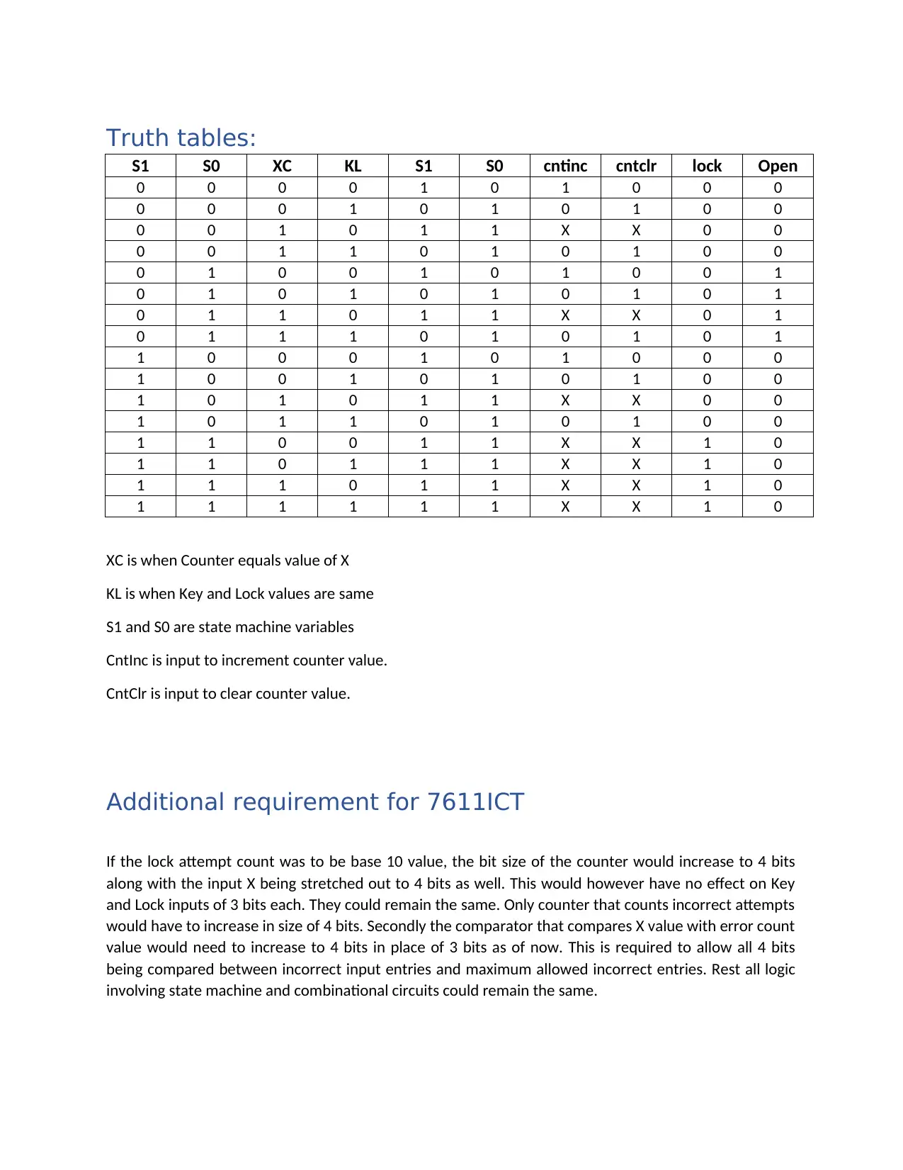
This assignment report details the design of a circuit as a state machine, addressing the requirements of the 1007ICT/7611ICT course. The circuit manages incorrect entry attempts and locks the system after a specified count. The solution includes two parts: Part A, a 3-bit comparator, and Part B, which utilizes the comparator within the state machine. The report presents circuit diagrams, truth tables, and descriptions of the states (Reset, Correct, Incorrect, and Lock). The functionality of the EXOR and NOR gates is explained. The design incorporates D flip-flops to define states and generates control signals such as CntInc, CntClr, Lock, and Open. The report also addresses an additional requirement for the 7611ICT course, discussing the impact of using a base-10 count for lock attempts and the necessary adjustments to the counter and comparator bit sizes. The student has used the Logisim simulator to create the circuits and provided a written report in PDF format.
tabler-icon-diamond-filled.svg

Contribute Materials

Your contribution can guide someone’s learning journey. Share your documents today.
Document Page
Course Title
Project Name
Student Name: Manikarnika Rajoriya
Student ID: s5197037
tabler-icon-diamond-filled.svg

Secure Best Marks with AI Grader

Need help grading? Try our AI Grader for instant feedback on your assignments.
Document Page
Contents
Circuit Function:..........................................................................................................................................2
Part A.......................................................................................................................................................2
Part B.......................................................................................................................................................2
Circuit diagrams:..........................................................................................................................................3
Part A.......................................................................................................................................................3
Part B.......................................................................................................................................................4
Truth tables:................................................................................................................................................5
Additional requirement for 7611ICT............................................................................................................5
Circuit Function:
Circuit is designed as a state machine. It keeps count of number of incorrect entries. When number of
incorrect entries matches the Specified count, the circuit locks the system. Else it waits for correct key to
be provided to open the lock. Thus, circuit has 4 states, the reset or initial state. The correct state which
is attained once correct key sequence is entered. Third state is incorrect state which is entered if
provided Key value mismatch the Lock value. Finally, is the Lock state, which is entered once X number
of consecutive incorrect attempts are made. Lock state can only be cleared by reset.
Part A:
Part A is a 3 bit comparator that checks if two inputs are same. It uses EXOR function for each bit and
then combines the output from three bits into single bit NOR logic. Each gate for EXOR is designed using
basic 3 input gates. NOR is designed using OR gates and final output is inverted using NOT gate.
Part B:
Part B makes use of comparator designed in Part A. It checks Key value with respect to Lock value. And
second instance of comparator checks incorrect sequences entered with respect to allowed count for
incorrect sequences.
There are two D flip flops for state machine. A flip flop is a memory element that can hold the last input
value it is triggered by an external clock again when it picks the new value. The flip flops form the state
variables S1 and S0. Together they can be used to represent up to 4 states of an FSM. The four states in
our circuit are Reset denoted by 00. Correct input key lock combination denoted by 01. Incorrect key
lock combination denoted by 10 and Lock state denoted by 11.
Key input is provided as 3-bit input. Lock value is also marked as L and is a 3-bit input. X is the 3 bit input
to mark count of incorrect attempts allowed before system locks down. Reset is a master signal to bring
the system into initial state after lock down.
Document Page
The valid signal indicates when the input Key and Lock values are valid and should be sampled. Thus,
valid signal is connected to clock input of counter and the state machine. Different control signals like
CntClr and CntInc are generated based on Key being same as Lock or otherwise. The Lock and Open
signals are generated based on state of the state machine.
If state machine is in state (01) it means correct key value was sampled and open signal is asserted. If
state machine is in state (11) it means number of incorrect entries is equal to maximum allowed entries.
Hence lock signal is asserted. State (00) is the reset state and achieved when reset signal is asserted that
also clears the already asserted open or lock signals. The state (10) is incorrect state which means
neither the entered key value is correct nor the number of incorrect entries has matched defined count
of incorrect entries.
Circuit diagrams:
Part A
Document Page
Part B
tabler-icon-diamond-filled.svg

Secure Best Marks with AI Grader

Need help grading? Try our AI Grader for instant feedback on your assignments.
Document Page
Truth tables:
S1 S0 XC KL S1 S0 cntinc cntclr lock Open
0 0 0 0 1 0 1 0 0 0
0 0 0 1 0 1 0 1 0 0
0 0 1 0 1 1 X X 0 0
0 0 1 1 0 1 0 1 0 0
0 1 0 0 1 0 1 0 0 1
0 1 0 1 0 1 0 1 0 1
0 1 1 0 1 1 X X 0 1
0 1 1 1 0 1 0 1 0 1
1 0 0 0 1 0 1 0 0 0
1 0 0 1 0 1 0 1 0 0
1 0 1 0 1 1 X X 0 0
1 0 1 1 0 1 0 1 0 0
1 1 0 0 1 1 X X 1 0
1 1 0 1 1 1 X X 1 0
1 1 1 0 1 1 X X 1 0
1 1 1 1 1 1 X X 1 0
XC is when Counter equals value of X
KL is when Key and Lock values are same
S1 and S0 are state machine variables
CntInc is input to increment counter value.
CntClr is input to clear counter value.
Additional requirement for 7611ICT
If the lock attempt count was to be base 10 value, the bit size of the counter would increase to 4 bits
along with the input X being stretched out to 4 bits as well. This would however have no effect on Key
and Lock inputs of 3 bits each. They could remain the same. Only counter that counts incorrect attempts
would have to increase in size of 4 bits. Secondly the comparator that compares X value with error count
value would need to increase to 4 bits in place of 3 bits as of now. This is required to allow all 4 bits
being compared between incorrect input entries and maximum allowed incorrect entries. Rest all logic
involving state machine and combinational circuits could remain the same.
chevron_up_icon
1 out of 5
circle_padding
hide_on_mobile
zoom_out_icon
logo.png

Your All-in-One AI-Powered Toolkit for Academic Success.

Available 24*7 on WhatsApp / Email

[object Object]