1007ICT/7611ICT Computer Systems Circuit Design Assignment

Verified

Added on  2023/04/23

|7
|703
|163
Practical Assignment
AI Summary
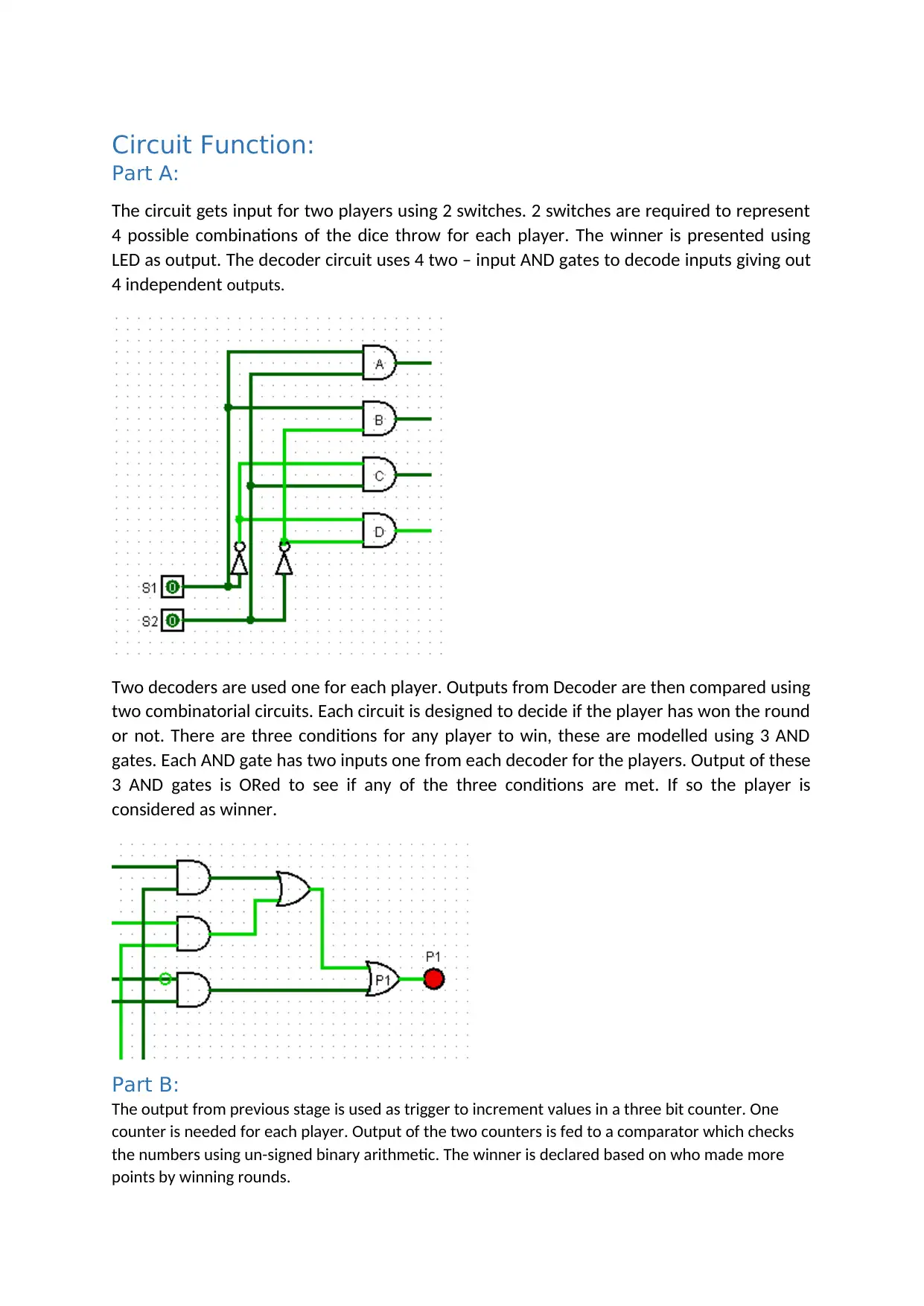
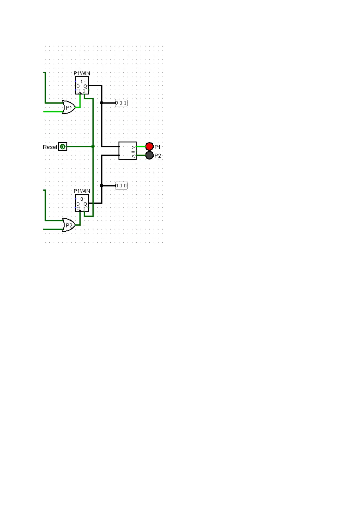
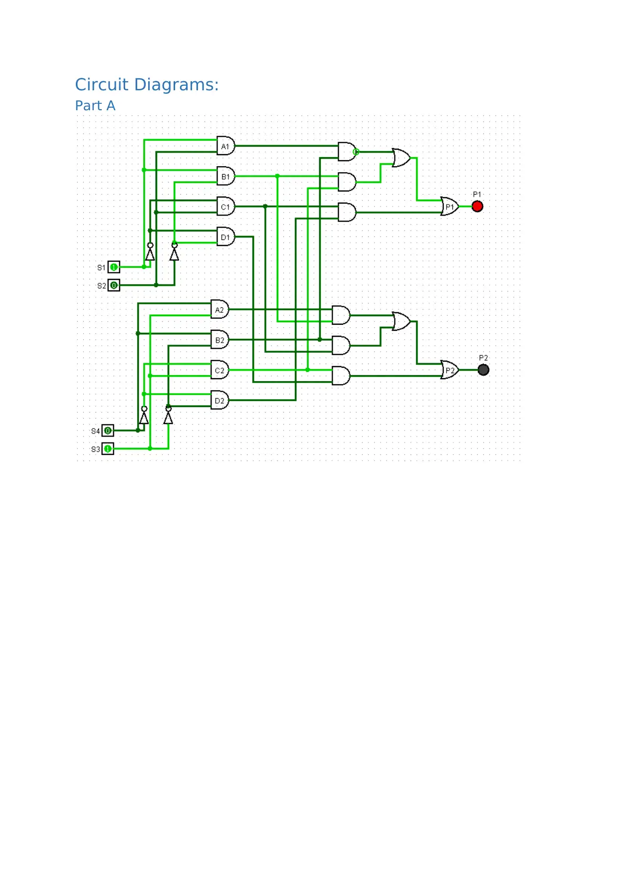
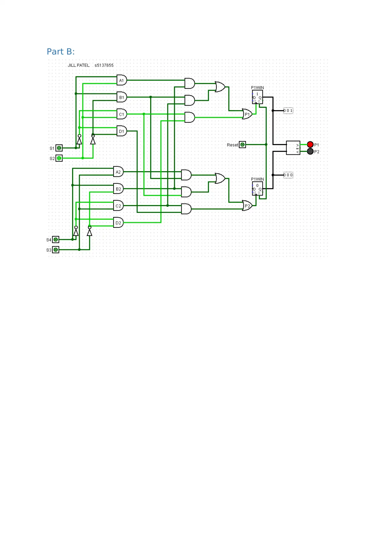
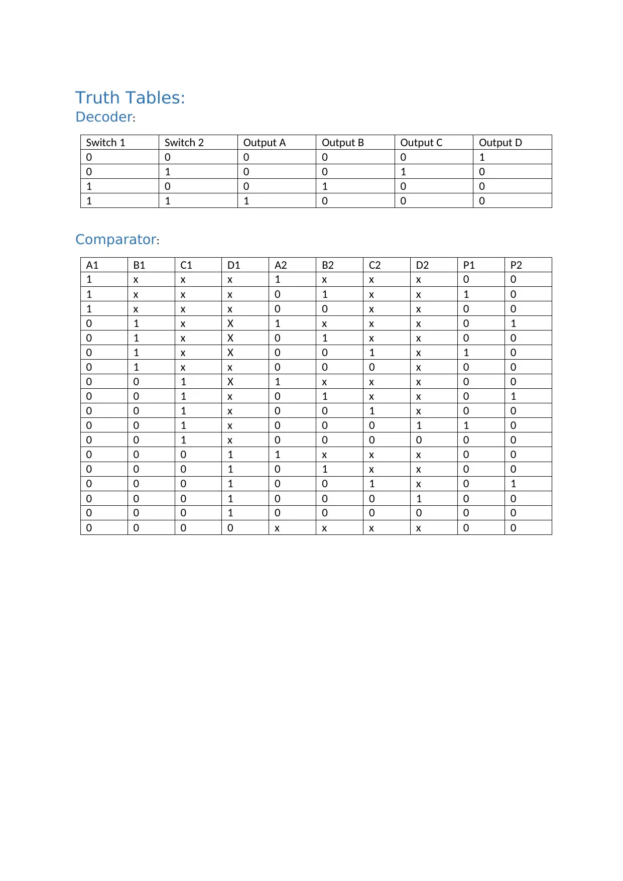
This assignment solution details the design and implementation of a digital circuit using the Logisim simulator. The circuit is designed to simulate a game for two players using dice throws. Part A of the circuit utilizes switches as inputs, decoders to interpret the dice combinations, and combinatorial circuits (AND and OR gates) to determine the winner of each round. Truth tables for the decoder and comparator are provided. The assignment is then upgraded to handle 8-faced dice, requiring modifications to the decoder and decision circuits. Part B of the circuit utilizes counters and a comparator to track the score and declare the overall winner based on the number of rounds won. The solution includes circuit diagrams and truth tables to explain the design and functionality of the circuit, covering the logic gates and components used. The assignment adheres to the specific requirements of the 1007ICT/7611ICT course, including file naming conventions for submission.
Document Page
Name:
Student Number:
E-Mail Address:
tabler-icon-diamond-filled.svg

Paraphrase This Document

Need a fresh take? Get an instant paraphrase of this document with our AI Paraphraser
Document Page
Circuit Function:
Part A:
The circuit gets input for two players using 2 switches. 2 switches are required to represent
4 possible combinations of the dice throw for each player. The winner is presented using
LED as output. The decoder circuit uses 4 two – input AND gates to decode inputs giving out
4 independent outputs.
Two decoders are used one for each player. Outputs from Decoder are then compared using
two combinatorial circuits. Each circuit is designed to decide if the player has won the round
or not. There are three conditions for any player to win, these are modelled using 3 AND
gates. Each AND gate has two inputs one from each decoder for the players. Output of these
3 AND gates is ORed to see if any of the three conditions are met. If so the player is
considered as winner.
Part B:
The output from previous stage is used as trigger to increment values in a three bit counter. One
counter is needed for each player. Output of the two counters is fed to a comparator which checks
the numbers using un-signed binary arithmetic. The winner is declared based on who made more
points by winning rounds.
Document Page
Document Page
Circuit Diagrams:
Part A
tabler-icon-diamond-filled.svg

Paraphrase This Document

Need a fresh take? Get an instant paraphrase of this document with our AI Paraphraser
Document Page
Part B:
Document Page
Truth Tables:
Decoder:
Switch 1 Switch 2 Output A Output B Output C Output D
0 0 0 0 0 1
0 1 0 0 1 0
1 0 0 1 0 0
1 1 1 0 0 0
Comparator:
A1 B1 C1 D1 A2 B2 C2 D2 P1 P2
1 x x x 1 x x x 0 0
1 x x x 0 1 x x 1 0
1 x x x 0 0 x x 0 0
0 1 x X 1 x x x 0 1
0 1 x X 0 1 x x 0 0
0 1 x X 0 0 1 x 1 0
0 1 x x 0 0 0 x 0 0
0 0 1 X 1 x x x 0 0
0 0 1 x 0 1 x x 0 1
0 0 1 x 0 0 1 x 0 0
0 0 1 x 0 0 0 1 1 0
0 0 1 x 0 0 0 0 0 0
0 0 0 1 1 x x x 0 0
0 0 0 1 0 1 x x 0 0
0 0 0 1 0 0 1 x 0 1
0 0 0 1 0 0 0 1 0 0
0 0 0 1 0 0 0 0 0 0
0 0 0 0 x x x x 0 0
Document Page
Additional Requirements for 7611ICT:
To upgrade and use 8 faced dice, the possible number of options that can be input to the
circuit increase. This will need 3 switches for each player to allow representation of 8
individual values. Since input is now 3 bits wide and 8 possible combinations exist, the size
of decoder used in Part A shall need to be increased to allow decoding of 8 unique outputs.
It needs to use 8 AND gates with 3 inputs each to decode and represent 8 individual
outputs. Since rules of the game still remain the same, the number of conditions to decide
the winner would also increase from 3 to 7 . Therefore, the decision circuit would need 7
AND gates in place of 3 for the decision part for each player. Depending upon number of
inputs allowed in OR gate, the number of OR gates shall also increase to allow ORing of 7
outputs from these 7 Gates. Final output of these OR gates will represent the winner as P1
and P2. These output of Part A will be fed to input of Part B. However, there is no change
needed in Part B to suit this new requirement. Winner will be indicated based on which
player wins 7 rounds before the other one.
chevron_up_icon
1 out of 7
circle_padding
hide_on_mobile
zoom_out_icon
[object Object]