Report: Design and Simulation of Digital Circuits using Logisim
VerifiedAdded on 2021/06/17
|13
|1950
|27
Report
AI Summary
This report provides a comprehensive overview of the Logisim simulator, an educational tool used for designing and simulating digital logic circuits. It begins with an introduction to Logisim, highlighting its features such as a user-friendly toolbar interface and the ability to build complex circuits from smaller sub-circuits. The report then details the design and simulation of an XOR gate using Logisim, including adding gates, wires, and text, as well as testing the circuit. It further discusses the working of Logisim, emphasizing its four key steps: designing the XOR gate, adding gates, adding wires, and testing the circuit. The report also covers the software's capabilities, including support for various operating systems and its open-source nature. It concludes with a discussion of Logisim's limitations, such as its reliance on the Java Virtual Machine and limitations in circuit layout and timing, while emphasizing its usefulness as an educational tool for understanding digital circuit design principles. Finally, the report offers a list of references to support its content.
COMPUTER SYSTEMS AND
NETWORKS
NETWORKS
Paraphrase This Document
Need a fresh take? Get an instant paraphrase of this document with our AI Paraphraser
Contents
CHAPTER 1..............................................................................................................................................2
INTRODUCTION.....................................................................................................................................2
CHAPTER 2:.............................................................................................................................................2
LOGISIM SIMULATOR:........................................................................................................................2
2.1 LOGISIM SIMULATOR DESIGN:..................................................................................................3
2.2 FEATURES OF LOGISIM SIMULATOR:......................................................................................3
CHAPTER 3:.............................................................................................................................................4
WORKING OF LOGISIM.......................................................................................................................4
3.1 DESIGN XOR GATE..........................................................................................................................4
3.2 ADDING GATES................................................................................................................................5
3.3 ADDING WIRES.................................................................................................................................6
3.4 ADDING TEXT...................................................................................................................................7
3.5 TESTING THE CIRCUIT..................................................................................................................7
CHAPTER 4..............................................................................................................................................9
CONCLUSION..........................................................................................................................................9
CHAPTER 5..............................................................................................................................................9
LIMITATIONS.........................................................................................................................................9
1
CHAPTER 1
INTRODUCTION
The digital circuit designed by the use of logisim simulator. Logisim is an educational
tool to support designing and simulating digital logic circuits. And it has the simple toolbar
interface and simulation of circuits. It is easy to learn the concepts of logic circuits. It has the
capacity to build the large circuits from small sub circuit. And it is used to draw the bundles of
wires with a single mouse drag. Logisim is used to design and simulate the whole CPU for
educational issues. It was designed by Carl Burch. Logisim is used by students in college at
many classes. The user can draw the circuit’s logic gates using the toolbox model to drawing
programs. The circuit had generated the values automatically by using major tool. And the user
can change the switches and check how the circuits act in the situations (Al-Busaidi, 2013).
CHAPTER 2:
LOGISIM SIMULATOR:
Logisim means logic simulator. They are used to allow the circuit design and simulation.
GUI (Graphical User Interface) are used to perform the circuit design process. Logisim are
support types of operating system such as Windows, Linux, macOS. The main advantage of
logisim is a free software design (Burch, 2002).
Mostly logisim are used to design the digital circuit, and also done some experimentation.
Traditional drawing programs are mostly similar to the circuit design using GUI. In logisim it
allows the user to edit the circuit. Suppose there was a problem in this circuit we can easily
modify the circuit. This software is mainly used in educational purpose.
2
⊘ This is a preview!⊘
Do you want full access?
Subscribe today to unlock all pages.
Trusted by 1+ million students worldwide
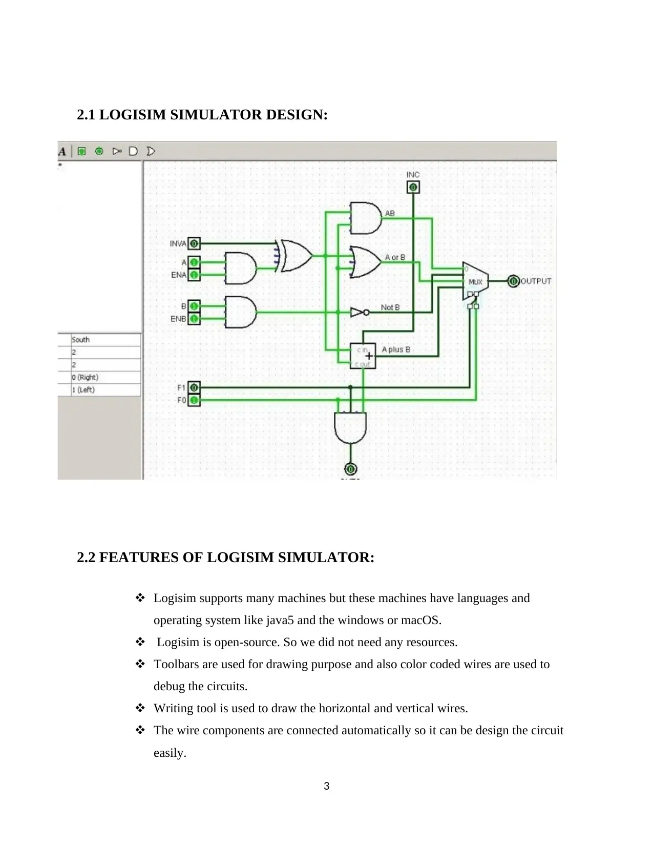
2.1 LOGISIM SIMULATOR DESIGN:
2.2 FEATURES OF LOGISIM SIMULATOR:
Logisim supports many machines but these machines have languages and
operating system like java5 and the windows or macOS.
Logisim is open-source. So we did not need any resources.
Toolbars are used for drawing purpose and also color coded wires are used to
debug the circuits.
Writing tool is used to draw the horizontal and vertical wires.
The wire components are connected automatically so it can be design the circuit
easily.
3
Paraphrase This Document
Need a fresh take? Get an instant paraphrase of this document with our AI Paraphraser
At last the circuit design successfully completed, and save the circuit in the form
of files or like GIF files and we must print the circuit using the printer (Saltzer &
Kaashoek, 2009).
Each circuit has different components such as input, output, RAM memory, flip
flop, arithmetic circuit, etc.
CHAPTER 3:
WORKING OF LOGISIM
Logisim used to design and simulate the logic circuits. It uses the educational tool
to know about the circuit work. It had four steps to explain about the work. They are,
Design XOR gate
Adding gates
Adding wires
Adding text
Testing the circuit
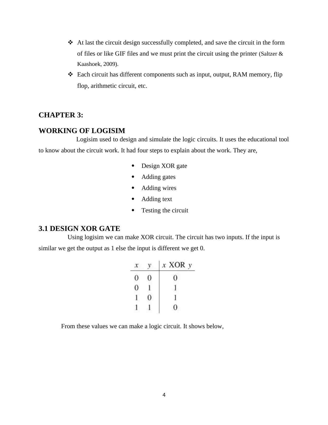
3.1 DESIGN XOR GATE
Using logisim we can make XOR circuit. The circuit has two inputs. If the input is
similar we get the output as 1 else the input is different we get 0.
From these values we can make a logic circuit. It shows below,
4
of files or like GIF files and we must print the circuit using the printer (Saltzer &
Kaashoek, 2009).
Each circuit has different components such as input, output, RAM memory, flip
flop, arithmetic circuit, etc.
CHAPTER 3:
WORKING OF LOGISIM
Logisim used to design and simulate the logic circuits. It uses the educational tool
to know about the circuit work. It had four steps to explain about the work. They are,
Design XOR gate
Adding gates
Adding wires
Adding text
Testing the circuit
3.1 DESIGN XOR GATE
Using logisim we can make XOR circuit. The circuit has two inputs. If the input is
similar we get the output as 1 else the input is different we get 0.
From these values we can make a logic circuit. It shows below,
4
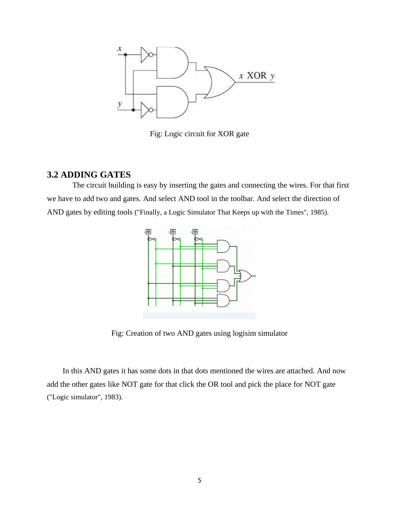
Fig: Logic circuit for XOR gate
3.2 ADDING GATES
The circuit building is easy by inserting the gates and connecting the wires. For that first
we have to add two and gates. And select AND tool in the toolbar. And select the direction of
AND gates by editing tools ("Finally, a Logic Simulator That Keeps up with the Times", 1985).
Fig: Creation of two AND gates using logisim simulator
In this AND gates it has some dots in that dots mentioned the wires are attached. And now
add the other gates like NOT gate for that click the OR tool and pick the place for NOT gate
("Logic simulator", 1983).
5
⊘ This is a preview!⊘
Do you want full access?
Subscribe today to unlock all pages.
Trusted by 1+ million students worldwide
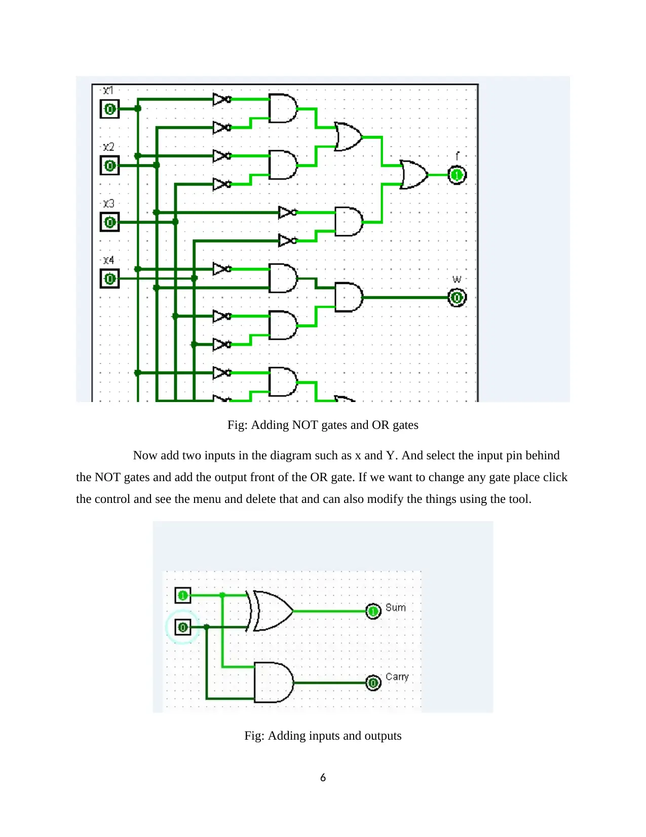
Fig: Adding NOT gates and OR gates
Now add two inputs in the diagram such as x and Y. And select the input pin behind
the NOT gates and add the output front of the OR gate. If we want to change any gate place click
the control and see the menu and delete that and can also modify the things using the tool.
Fig: Adding inputs and outputs
6
Paraphrase This Document
Need a fresh take? Get an instant paraphrase of this document with our AI Paraphraser
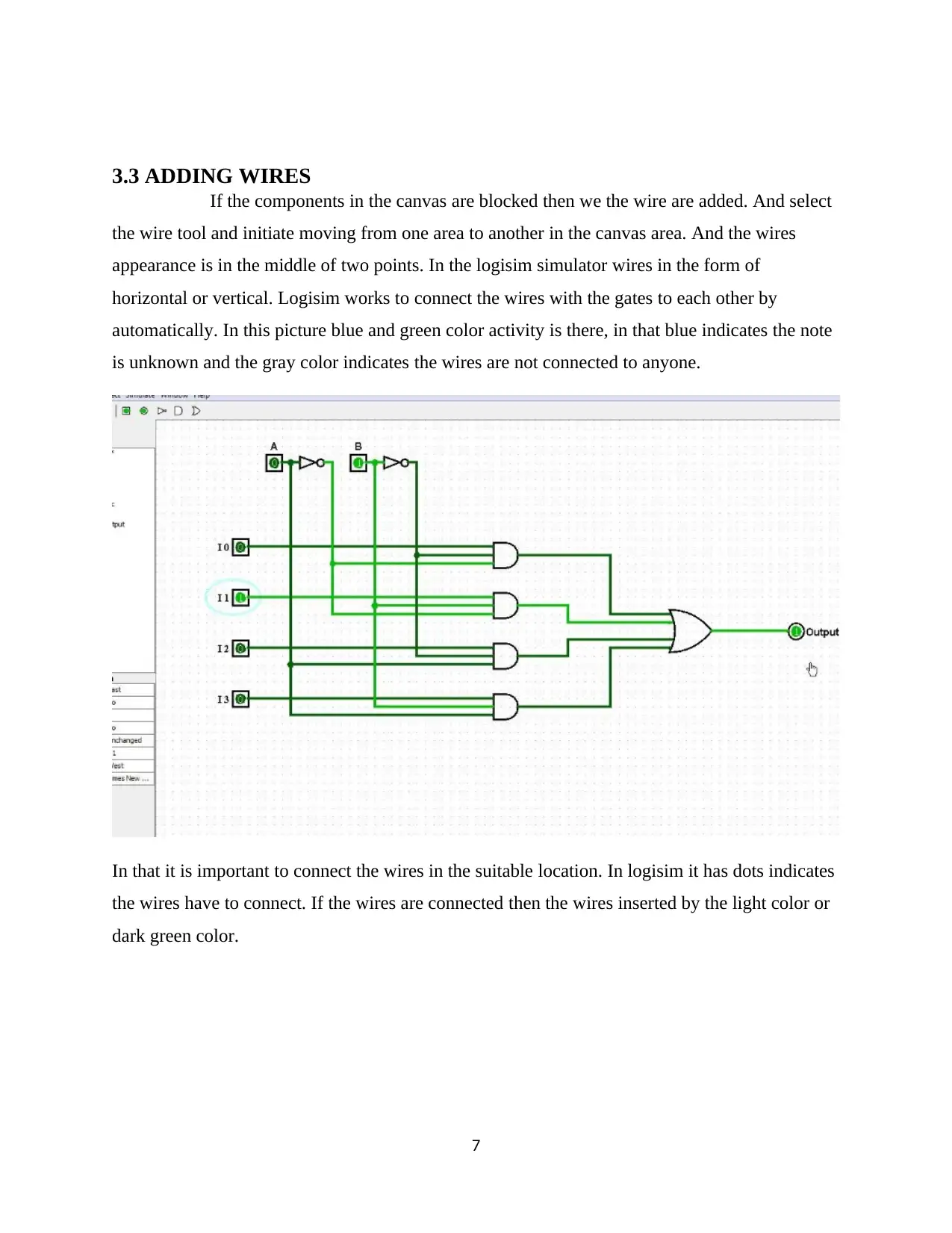
3.3 ADDING WIRES
If the components in the canvas are blocked then we the wire are added. And select
the wire tool and initiate moving from one area to another in the canvas area. And the wires
appearance is in the middle of two points. In the logisim simulator wires in the form of
horizontal or vertical. Logisim works to connect the wires with the gates to each other by
automatically. In this picture blue and green color activity is there, in that blue indicates the note
is unknown and the gray color indicates the wires are not connected to anyone.
In that it is important to connect the wires in the suitable location. In logisim it has dots indicates
the wires have to connect. If the wires are connected then the wires inserted by the light color or
dark green color.
7
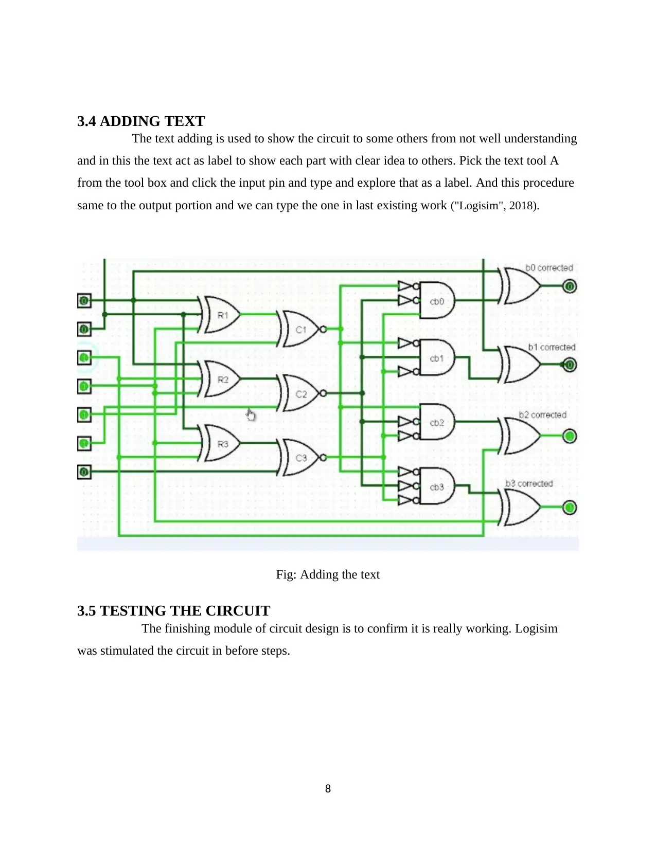
3.4 ADDING TEXT
The text adding is used to show the circuit to some others from not well understanding
and in this the text act as label to show each part with clear idea to others. Pick the text tool A
from the tool box and click the input pin and type and explore that as a label. And this procedure
same to the output portion and we can type the one in last existing work ("Logisim", 2018).
Fig: Adding the text
3.5 TESTING THE CIRCUIT
The finishing module of circuit design is to confirm it is really working. Logisim
was stimulated the circuit in before steps.
8
⊘ This is a preview!⊘
Do you want full access?
Subscribe today to unlock all pages.
Trusted by 1+ million students worldwide
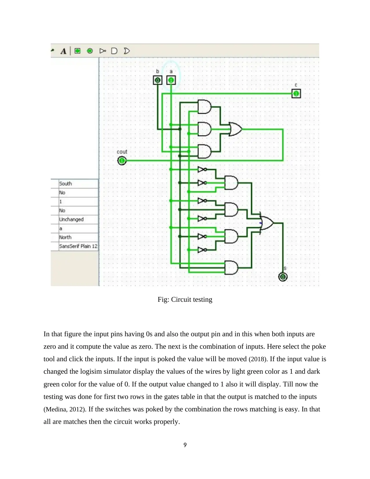
Fig: Circuit testing
In that figure the input pins having 0s and also the output pin and in this when both inputs are
zero and it compute the value as zero. The next is the combination of inputs. Here select the poke
tool and click the inputs. If the input is poked the value will be moved (2018). If the input value is
changed the logisim simulator display the values of the wires by light green color as 1 and dark
green color for the value of 0. If the output value changed to 1 also it will display. Till now the
testing was done for first two rows in the gates table in that the output is matched to the inputs
(Medina, 2012). If the switches was poked by the combination the rows matching is easy. In that
all are matches then the circuit works properly.
9
Paraphrase This Document
Need a fresh take? Get an instant paraphrase of this document with our AI Paraphraser
CHAPTER 4
CONCLUSION
Logisim is the most famous educational tool. Because this tool used by the
students for their educational purpose.
Which are used to simulate the digital circuit .And also we can easily understand
the concept of this circuit. The designer easily learns the functionality of the circuit. And also
tells the details about voltage, timing, impedance and so on (White, Fisch & Pooch, n.d.).
Logisim reduce the execution timing. So the solution is generated very fast and
also effective. The main drawback in logisim is it does not support direct export of waveforms.
So we are using some mathematical operations. So using conjunction then exports
the waveforms. Some countries are not familiar about this logisim tool. Especially Bulgaria has a
little familiar about logisim tool.
Lack of elements are used in digital simulation like capacitors, inductors, they are
mainly used for the timing purpose. Using these elements we can easily set the time constants.
Finally the most important feature is fully open source’s, public easily get software. And also
freely modify the software.
CHAPTER 5
LIMITATIONS
Logisim have some limitations. The java virtual machine is the most familiar
logisim limitation device. Basically logisim is platform independence. So it supports any
platform. Installation process is very complicated. And also starting the program is very difficult.
These are the main drawbacks.
So avoid this problem simple scripts are followed in our windows and UNIX
computers. In laboratories is not a major problem but our home computers are affected.
Construction of the program is fully focused on the given efficient details. All the
circuits are in moderate size. So we cannot find the problems easily in our laboratory assignment.
10

Two types are coursed are used one is lower-division course and another one is
upper division architecture course. Logisim does not support the circuit layout issues, circuit
timing, and buses.
Fixed orientation has the collections of logisim components. They are used in
rotation of components. Sub circuit and surrounding circuits have a lot of pins. All the pins are in
one way.
CODING
11
⊘ This is a preview!⊘
Do you want full access?
Subscribe today to unlock all pages.
Trusted by 1+ million students worldwide
1 out of 13

Your All-in-One AI-Powered Toolkit for Academic Success.
+13062052269
info@desklib.com
Available 24*7 on WhatsApp / Email
![[object Object]](/_next/static/media/star-bottom.7253800d.svg)
Unlock your academic potential
Copyright © 2020–2026 A2Z Services. All Rights Reserved. Developed and managed by ZUCOL.