Configuring BGP Routing Lab: Network Topology and IP Addresses
VerifiedAdded on 2019/09/19
|2
|627
|393
Practical Assignment
AI Summary
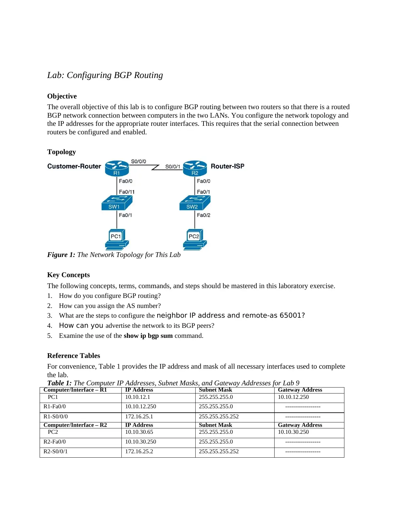
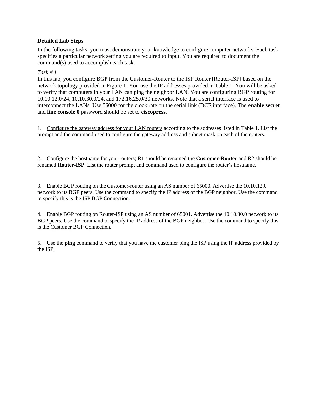
This lab assignment focuses on configuring Border Gateway Protocol (BGP) routing between two routers to establish a routed network connection. The objective is to configure the network topology and IP addresses for the appropriate router interfaces. The lab requires setting up the serial connection between the routers. The tasks involve configuring gateway addresses, hostnames, and enabling BGP routing on both routers using specified Autonomous System (AS) numbers. The student must advertise specific networks to their BGP peers, configure neighbor IP addresses, and verify network connectivity using the ping command. The lab covers key concepts such as configuring BGP routing, assigning AS numbers, advertising networks, and using the show ip bgp sum command. The assignment uses a specific network topology and IP addressing scheme, requiring the student to apply their knowledge of BGP configuration to establish communication between the two LANs. The configuration includes setting the clock rate on the serial link and configuring enable secret and line console passwords.
1 out of 2
Related Documents


Your All-in-One AI-Powered Toolkit for Academic Success.
+13062052269
info@desklib.com
Available 24*7 on WhatsApp / Email
![[object Object]](/_next/static/media/star-bottom.7253800d.svg)
Copyright © 2020–2026 A2Z Services. All Rights Reserved. Developed and managed by ZUCOL.