Connecting Rod Redesign: Reverse Engineering & FEA Validation
VerifiedAdded on 2023/06/14
|56
|4240
|96
Project
AI Summary
This project presents a detailed finite element analysis (FEA) and reverse engineering process applied to a connecting rod. The initial design of the connecting rod (Connecting Rod-1) is analyzed using ANSYS, focusing on stress distribution, total deformation, and safety factors under a 1000N compressive force. The material used is structural steel, and the analysis includes mechanical and fatigue safety factor assessments. Subsequently, reverse engineering is performed to optimize the connecting rod design (Connecting Rod-2) by removing excess material and modifying the groove shape to reduce weight by 0.153 kg. FEA is then conducted on the redesigned connecting rod, and the results are compared to assess improvements in stress concentration, deformation, and safety factors. The project also touches upon CAM processes and jig fixture considerations for manufacturing the connecting rod.
Contents
ABSTRACT....................................................................................................................................................6
Connecting Rod-1........................................................................................................................................7
FEA-1...........................................................................................................................................................8
Model......................................................................................................................................................8
Geometry.............................................................................................................................................8
Mesh..................................................................................................................................................11
Static Structural (A5)..............................................................................................................................14
Results...............................................................................................................................................18
Material Data.........................................................................................................................................27
Structural Steel..................................................................................................................................27
Explanation-...............................................................................................................................................28
Connecting Rod-2 (Reverse Engineering)..................................................................................................28
FEA -2........................................................................................................................................................30
Units......................................................................................................................................................30
Model....................................................................................................................................................30
Geometry...........................................................................................................................................30
Mesh..................................................................................................................................................33
Static Structural (A5)..............................................................................................................................36
Results-..............................................................................................................................................40
Material Data.........................................................................................................................................49
Structural Steel..................................................................................................................................49
Explanation-...............................................................................................................................................50
Comparison (Conclusion)...........................................................................................................................50
CAM-..........................................................................................................................................................51
Process-.................................................................................................................................................51
Reference-.................................................................................................................................................52
Paraphrase This Document
Need a fresh take? Get an instant paraphrase of this document with our AI Paraphraser
List of Figures
Figure 1 (Meshing).....................................................................................................................................13
Figure 2 (Meshing).....................................................................................................................................13
Figure 3 (Force-1)......................................................................................................................................15
Figure 4 (Force-1)......................................................................................................................................15
Figure 5 (Force-2)......................................................................................................................................16
Figure 6 (Force-2)......................................................................................................................................16
Figure 7 (Force-3)......................................................................................................................................17
Figure 8 (Force-3)......................................................................................................................................17
Figure 9 (Fixed Support)............................................................................................................................18
Figure 10 (Total Deformation-1)................................................................................................................19
Figure 11 (Total Deformation-2)................................................................................................................19
Figure 12 (Equivalent stress-1)..................................................................................................................20
Figure 13 (Equivalent stress-2)..................................................................................................................20
Figure 14 (Elastic strain-1).........................................................................................................................21
Figure 15 (Elastic strain-2).........................................................................................................................21
Figure 16 (Mechanical safety factor-1)......................................................................................................23
Figure 17 (Mechanical safety factor-2)......................................................................................................23
Figure 18 (Fatigue tool).............................................................................................................................24
Figure 19 (Fatigue tool solution)................................................................................................................25
Figure 20 (Fatigue safety factor-1).............................................................................................................26
Figure 21 (Fatigue safety factor-2).............................................................................................................26
Figure 22 (Connecting rod-2).....................................................................................................................35
Figure 23 (Fixed Support)..........................................................................................................................35
Figure 24 (Force-1)....................................................................................................................................37
Figure 25 (Force-1)....................................................................................................................................37
Figure 26 (Force-2)....................................................................................................................................38
Figure 27 (Force-2)....................................................................................................................................38
Figure 28 (Force-3)....................................................................................................................................39
Figure 29 (Force-3)....................................................................................................................................39
Figure 30 (Total Deformation-1)................................................................................................................41
Figure 31 (Total Diformation-2).................................................................................................................41
Figure 32 (Equivalent stress-1)..................................................................................................................42
Figure 33 (Equivalent stress-2)..................................................................................................................42
Figure 34 (Elastic strain-1).........................................................................................................................43
Figure 35 (Elastic strain-2).........................................................................................................................43
Figure 36 (Mechanical safety factor-1)......................................................................................................45
Figure 37 (Mechanical safety factor-2)......................................................................................................45
Figure 38 (Fatigue tool).............................................................................................................................46
Figure 39 (Fatigue tool solution)................................................................................................................47
Figure 40 (Fatigue safety factor-1).............................................................................................................48
Figure 41 (Fatigue safety factor-2).............................................................................................................48
Figure 42 (Jig fixture for connecting rod)...................................................................................................51
List of Tables
Table 1 (Geometry)......................................................................................................................................8
Table 2(Geometry parts)...........................................................................................................................10
Table 3(Mesh)............................................................................................................................................11
Table 4(Analysis)........................................................................................................................................14
Table 5(Loads)...........................................................................................................................................14
Table 6(Results).........................................................................................................................................18
Table 7(Stress safety tools)........................................................................................................................22
Table 8(Stress tools result)........................................................................................................................22
Table 9(Fatigue tools)................................................................................................................................24
Table 10(Fatigue tools result)....................................................................................................................25
Table 11(Material data).............................................................................................................................27
Table 12(Compressive Yield Strength).......................................................................................................27
Table 13(Tensile yield strength)................................................................................................................27
Table 14(Tensile Ultimate strength)..........................................................................................................27
Table 15(Alternating stress).......................................................................................................................27
Table 16 (Strain life parameter).................................................................................................................28
Table 17(isotropic elasticity)......................................................................................................................28
Table 18 (Units).........................................................................................................................................30
Table 19 (Geometry)..................................................................................................................................30
Table 20 (Geometry parts).........................................................................................................................32
Table 21 (Mesh).........................................................................................................................................33
Table 22 (Analysis).....................................................................................................................................36
Table 23 (Loads)........................................................................................................................................36
Table 24 (Results)......................................................................................................................................40
Table 25 (Stress safety tool)......................................................................................................................44
Table 26 (Stress tool result).......................................................................................................................44
Table 27 (Fatigue tools).............................................................................................................................46
Table 28 (Fatigue tools result)...................................................................................................................47
Table 29 (Material data)............................................................................................................................49
Table 30 (Compressive yield strength)......................................................................................................49
Table 31 (Tensile yield strength)................................................................................................................49
Table 32 (Alternating stress)......................................................................................................................49
Table 33 (Strain life parameter).................................................................................................................50
Table 34 (Isotropic elasticity).....................................................................................................................50
⊘ This is a preview!⊘
Do you want full access?
Subscribe today to unlock all pages.
Trusted by 1+ million students worldwide

ABSTRACT
Connecting rod plays very vital role in engine. It converts reciprocating motion to rotary motion and vice
versa. It connects the piston and crank shaft. As a result of which connecting rod undergo various
deformation under various forces. That’s why material selection and designing of connecting rod should
be done very precisely. Connecting rod must be light in weight and it must have good strength under
fatigue and other loads.
In this assignment first we will design connecting rod according to given dimensions. After that we will
do its FEA in ANSYS. By doing so we will see how stresses going to damage the part or in other words we
will see stress concentration in the connecting rod.
Paraphrase This Document
Need a fresh take? Get an instant paraphrase of this document with our AI Paraphraser
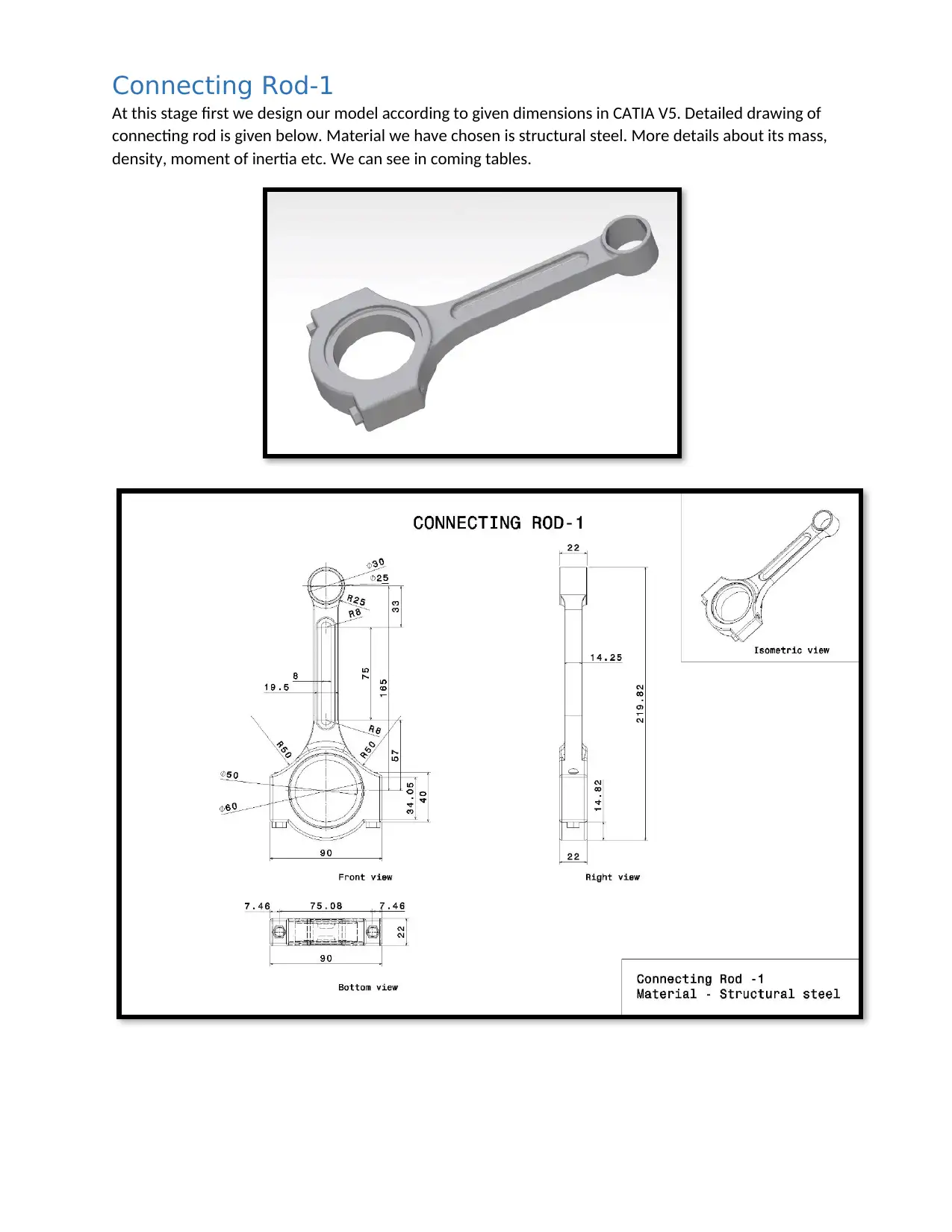
Connecting Rod-1
At this stage first we design our model according to given dimensions in CATIA V5. Detailed drawing of
connecting rod is given below. Material we have chosen is structural steel. More details about its mass,
density, moment of inertia etc. We can see in coming tables.
At this stage first we design our model according to given dimensions in CATIA V5. Detailed drawing of
connecting rod is given below. Material we have chosen is structural steel. More details about its mass,
density, moment of inertia etc. We can see in coming tables.
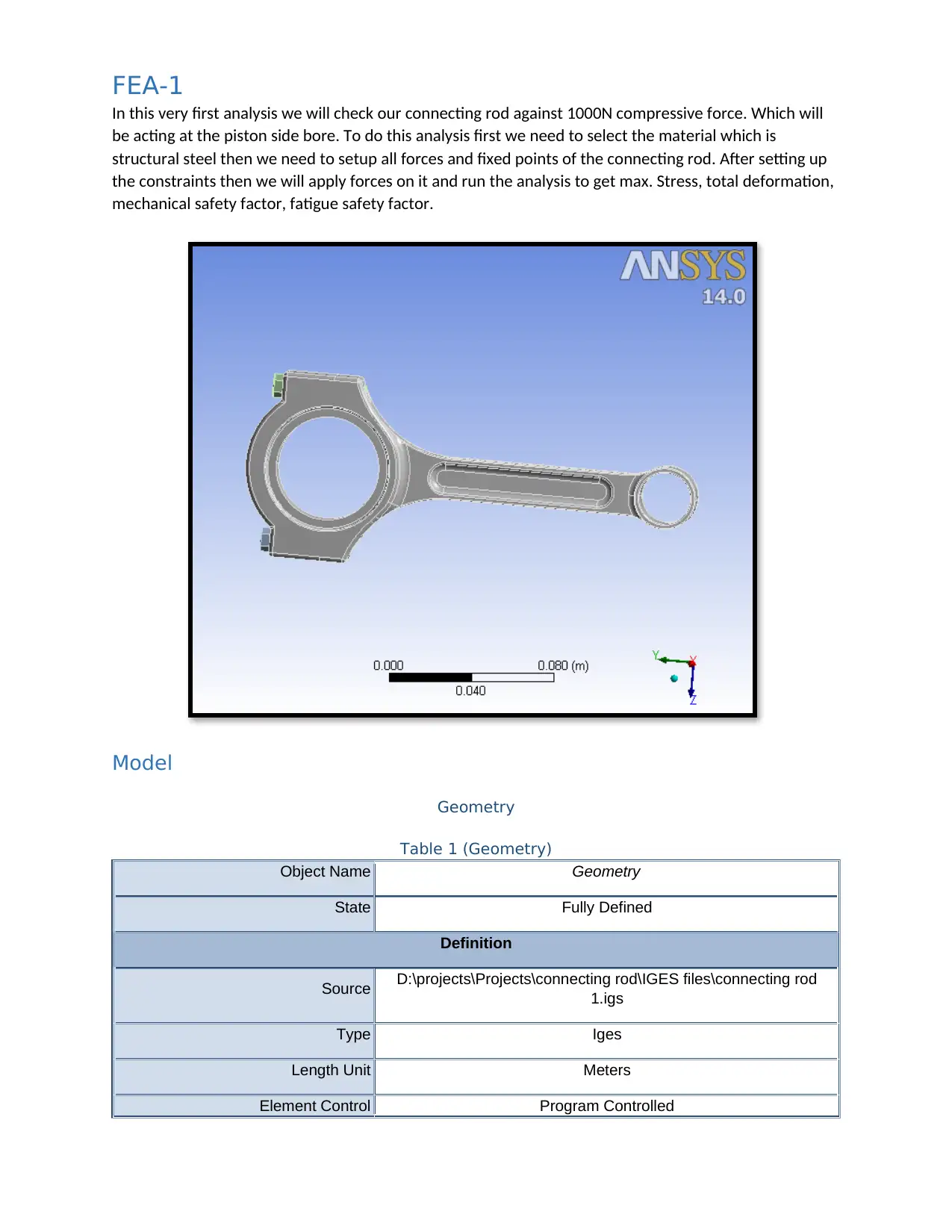
FEA-1
In this very first analysis we will check our connecting rod against 1000N compressive force. Which will
be acting at the piston side bore. To do this analysis first we need to select the material which is
structural steel then we need to setup all forces and fixed points of the connecting rod. After setting up
the constraints then we will apply forces on it and run the analysis to get max. Stress, total deformation,
mechanical safety factor, fatigue safety factor.
Model
Geometry
Table 1 (Geometry)
Object Name Geometry
State Fully Defined
Definition
Source D:\projects\Projects\connecting rod\IGES files\connecting rod
1.igs
Type Iges
Length Unit Meters
Element Control Program Controlled
⊘ This is a preview!⊘
Do you want full access?
Subscribe today to unlock all pages.
Trusted by 1+ million students worldwide
Display Style Body Color
Bounding Box
Length X 2.2e-002 m
Length Y 0.21982 m
Length Z 9.e-002 m
Properties
Volume 9.7912e-005 m³
Mass 0.76861 kg
Scale Factor Value 1.
Statistics
Bodies 3
Active Bodies 3
Nodes 46862
Elements 25912
Mesh Metric None
Basic Geometry Options
Solid Bodies Yes
Surface Bodies Yes
Line Bodies No
Parameters Yes
Parameter Key DS
Attributes No
Named Selections No
Material Properties No
Advanced Geometry Options
Use Associativity Yes
Coordinate Systems No
Reader Mode Saves Updated File No
Paraphrase This Document
Need a fresh take? Get an instant paraphrase of this document with our AI Paraphraser
Use Instances Yes
Smart CAD Update No
Attach File Via Temp File Yes
Temporary Directory C:\Users\AppData\Local\Temp
Analysis Type 3-D
Mixed Import Resolution None
Decompose Disjoint Faces Yes
Enclosure and Symmetry
Processing Yes
Table 2(Geometry parts)
Object Name Part 1 Part 2 Part 3
State Meshed
Graphics Properties
Visible Yes
Transparency 1
Definition
Suppressed No
Stiffness Behavior Flexible
Coordinate System Default Coordinate System
Reference Temperature By Environment
Material
Assignment Structural Steel
Nonlinear Effects Yes
Thermal Strain Effects Yes
Bounding Box
Length X 2.2e-002 m 1.e-002 m
Length Y 0.21982 m 4.5e-002 m
Length Z 9.e-002 m 1.1547e-002 m
Properties
Volume 9.3031e-005 m³ 2.4404e-006 m³
Mass 0.7303 kg 1.9157e-002 kg
Centroid X -1.4551e-007 m 1.0325e-010 m 7.6565e-010 m
Centroid Y 0.13458 m 0.17402 m
Centroid Z 1.4373e-006 m 3.7541e-002 m -3.7541e-002 m
Moment of Inertia Ip1 2.8921e-003 kg·m² 3.5775e-006 kg·m²
Moment of Inertia Ip2 4.0096e-004 kg·m² 1.7051e-007 kg·m²
Moment of Inertia Ip3 2.5366e-003 kg·m² 3.5776e-006 kg·m²
Statistics
Nodes 43041 1891 1930
Elements 23918 981 1013
Mesh Metric None
Mesh
Table 3(Mesh)
Object Name Mesh
State Solved
Defaults
Physics Preference Mechanical
Relevance 1
Sizing
Use Advanced Size Function Off
Relevance Center Fine
Element Size Default
Initial Size Seed Active Assembly
Smoothing High
Transition Fast
Span Angle Center Coarse
Minimum Edge Length 3.75e-004 m
⊘ This is a preview!⊘
Do you want full access?
Subscribe today to unlock all pages.
Trusted by 1+ million students worldwide
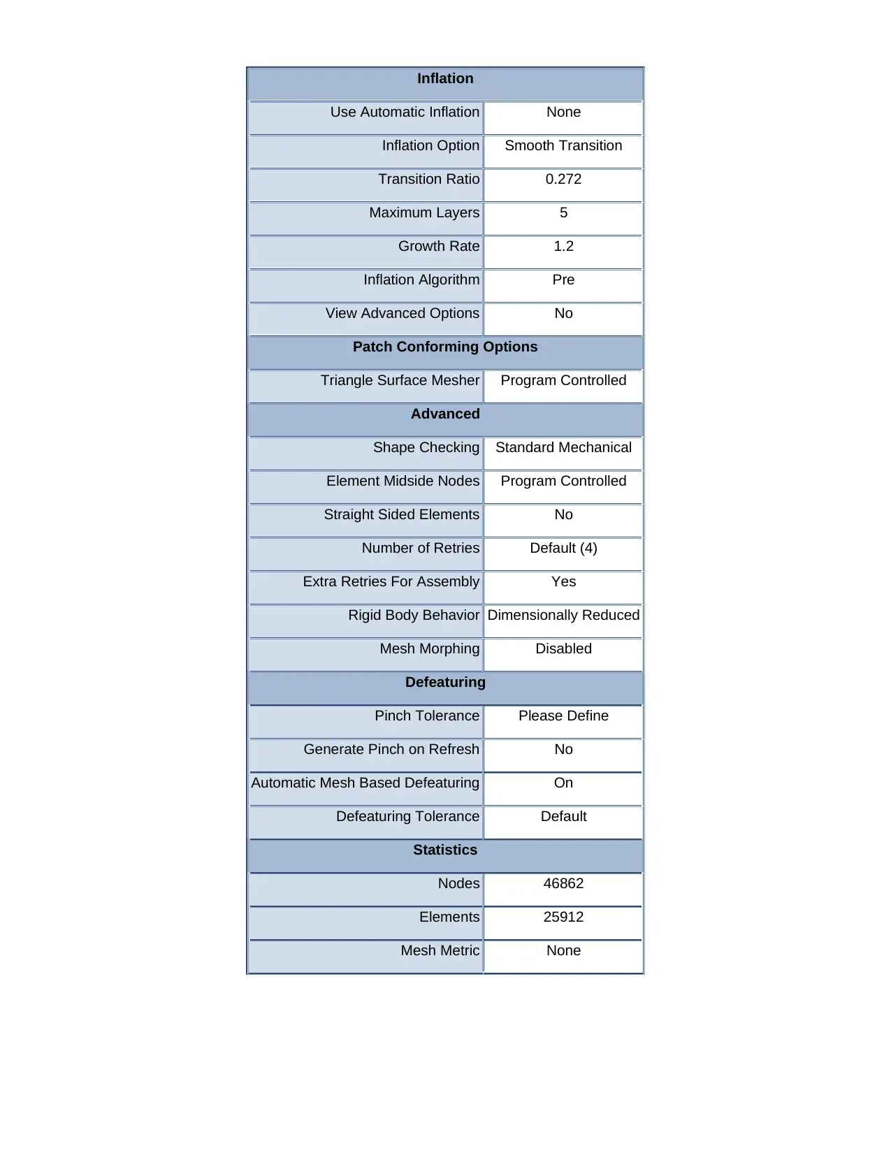
Inflation
Use Automatic Inflation None
Inflation Option Smooth Transition
Transition Ratio 0.272
Maximum Layers 5
Growth Rate 1.2
Inflation Algorithm Pre
View Advanced Options No
Patch Conforming Options
Triangle Surface Mesher Program Controlled
Advanced
Shape Checking Standard Mechanical
Element Midside Nodes Program Controlled
Straight Sided Elements No
Number of Retries Default (4)
Extra Retries For Assembly Yes
Rigid Body Behavior Dimensionally Reduced
Mesh Morphing Disabled
Defeaturing
Pinch Tolerance Please Define
Generate Pinch on Refresh No
Automatic Mesh Based Defeaturing On
Defeaturing Tolerance Default
Statistics
Nodes 46862
Elements 25912
Mesh Metric None
Paraphrase This Document
Need a fresh take? Get an instant paraphrase of this document with our AI Paraphraser
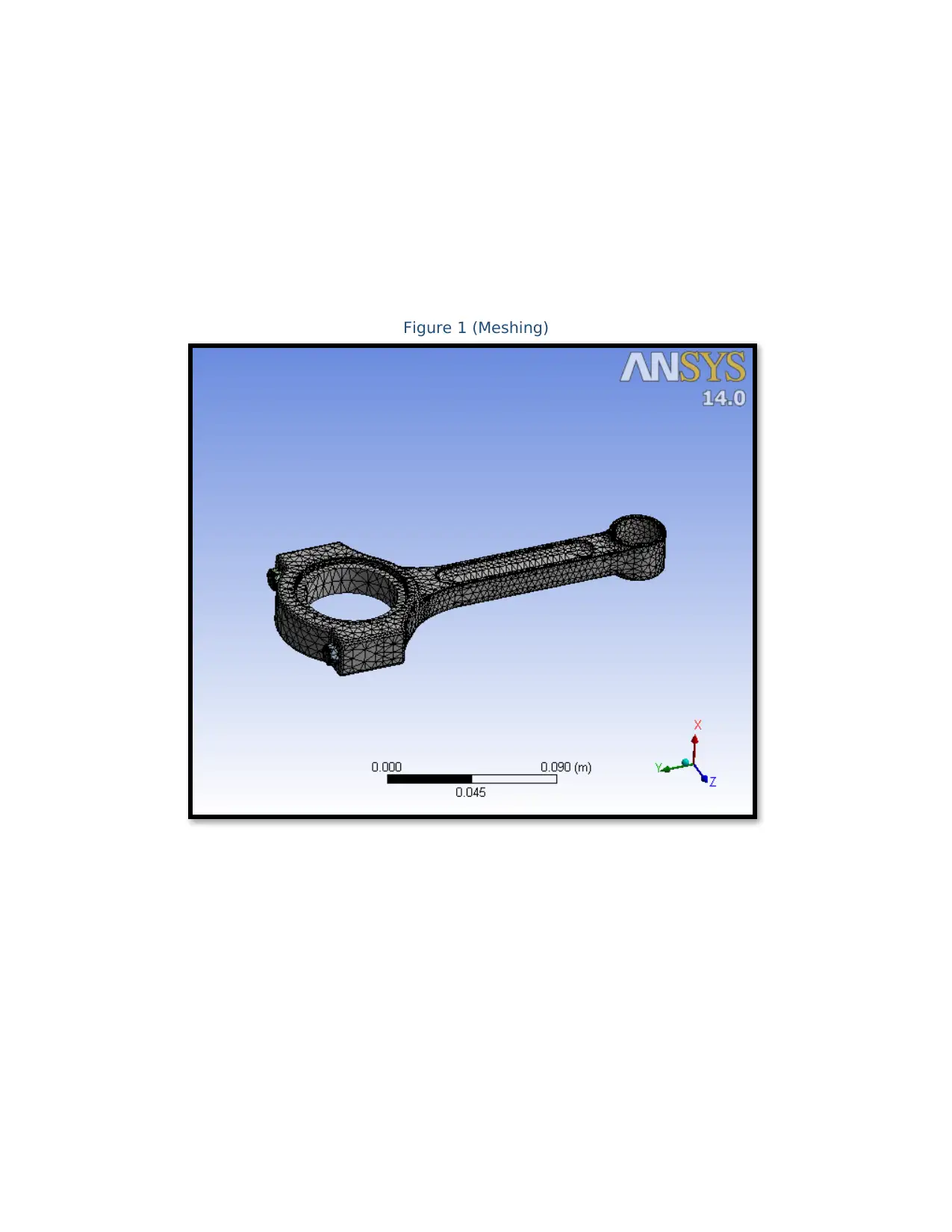
Figure 1 (Meshing)
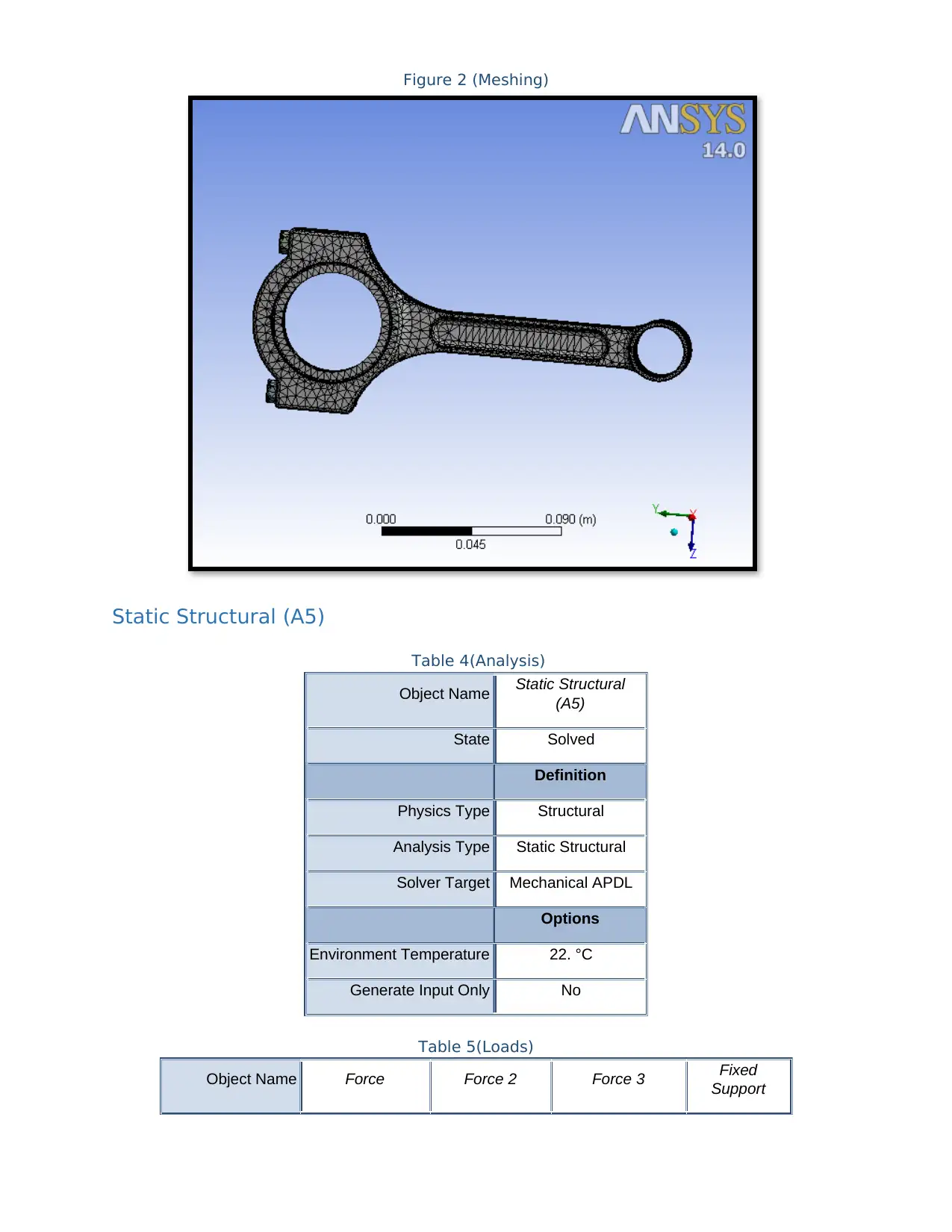
Figure 2 (Meshing)
Static Structural (A5)
Table 4(Analysis)
Object Name Static Structural
(A5)
State Solved
Definition
Physics Type Structural
Analysis Type Static Structural
Solver Target Mechanical APDL
Options
Environment Temperature 22. °C
Generate Input Only No
Table 5(Loads)
Object Name Force Force 2 Force 3 Fixed
Support
⊘ This is a preview!⊘
Do you want full access?
Subscribe today to unlock all pages.
Trusted by 1+ million students worldwide
1 out of 56
Related Documents


Your All-in-One AI-Powered Toolkit for Academic Success.
+13062052269
info@desklib.com
Available 24*7 on WhatsApp / Email
![[object Object]](/_next/static/media/star-bottom.7253800d.svg)
Unlock your academic potential
Copyright © 2020–2026 A2Z Services. All Rights Reserved. Developed and managed by ZUCOL.