Construction Information Production Report: 2017-18 Academic Year
VerifiedAdded on  2023/01/13
|18
|3027
|1
Report
AI Summary
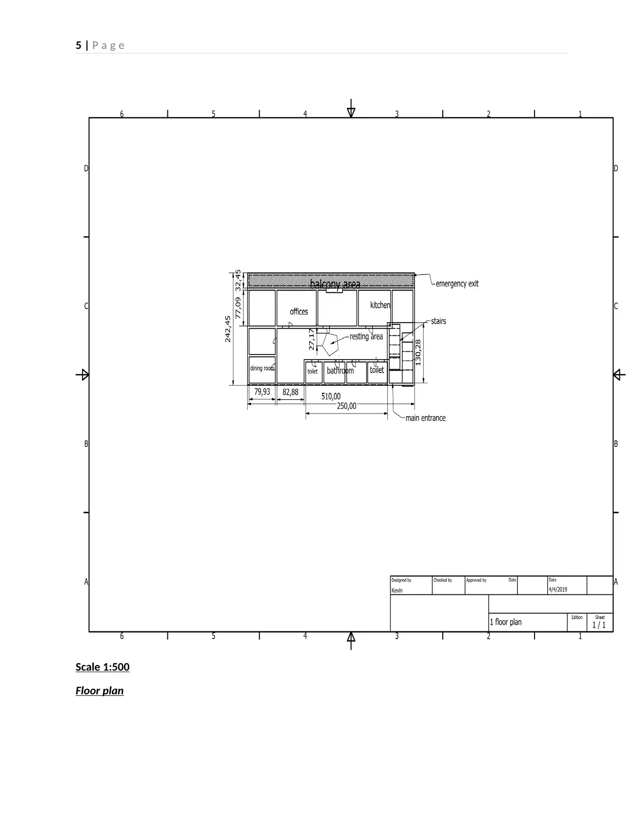
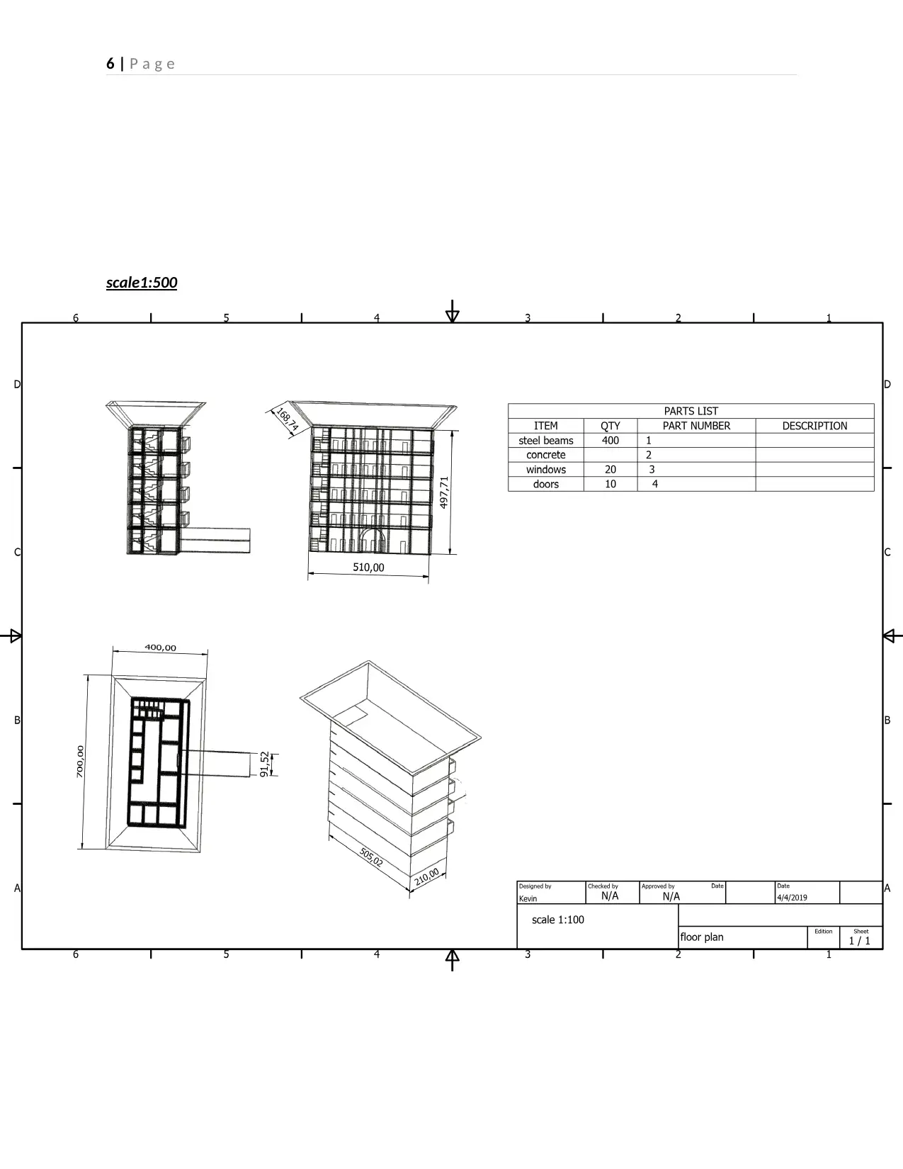
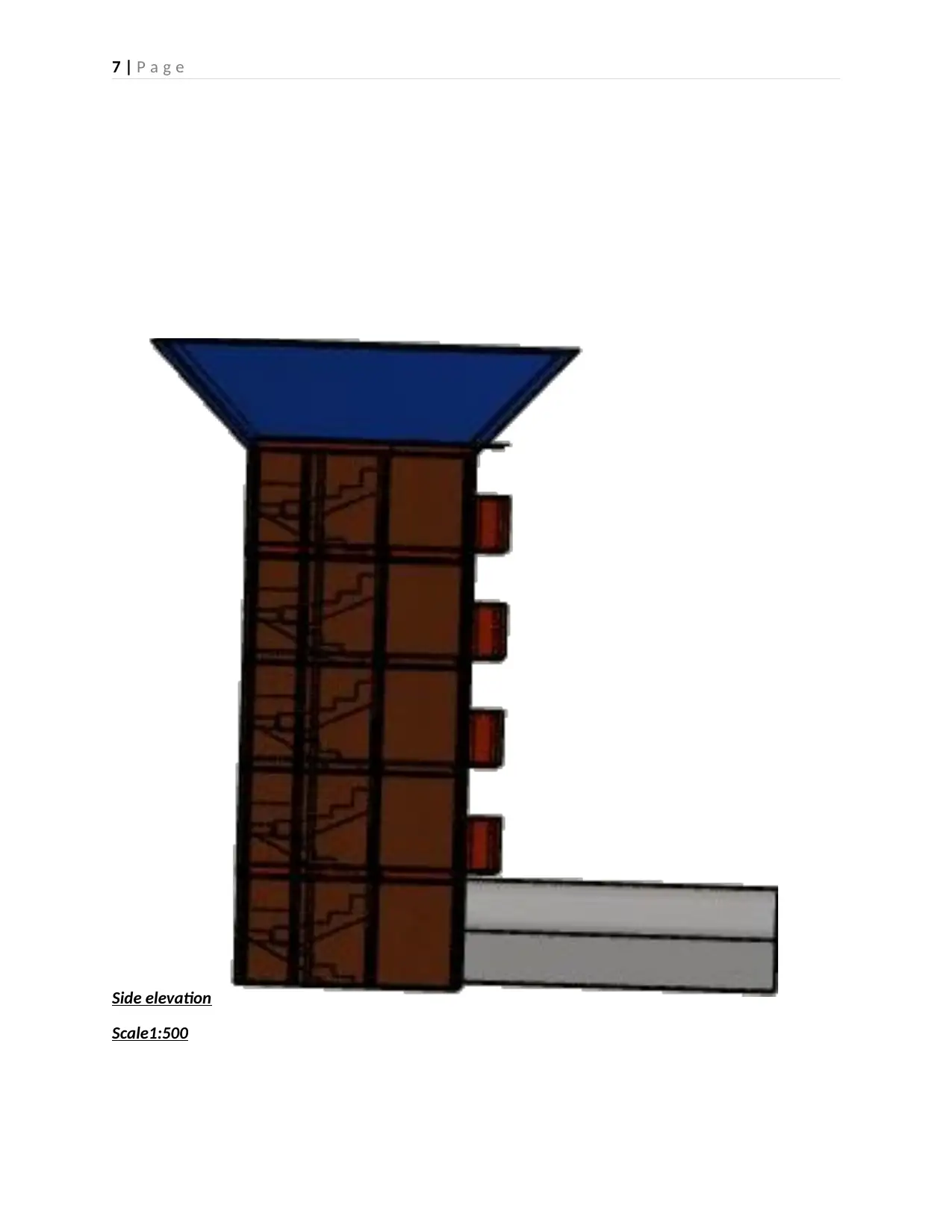
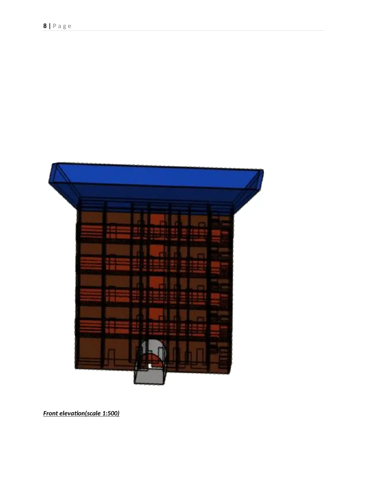
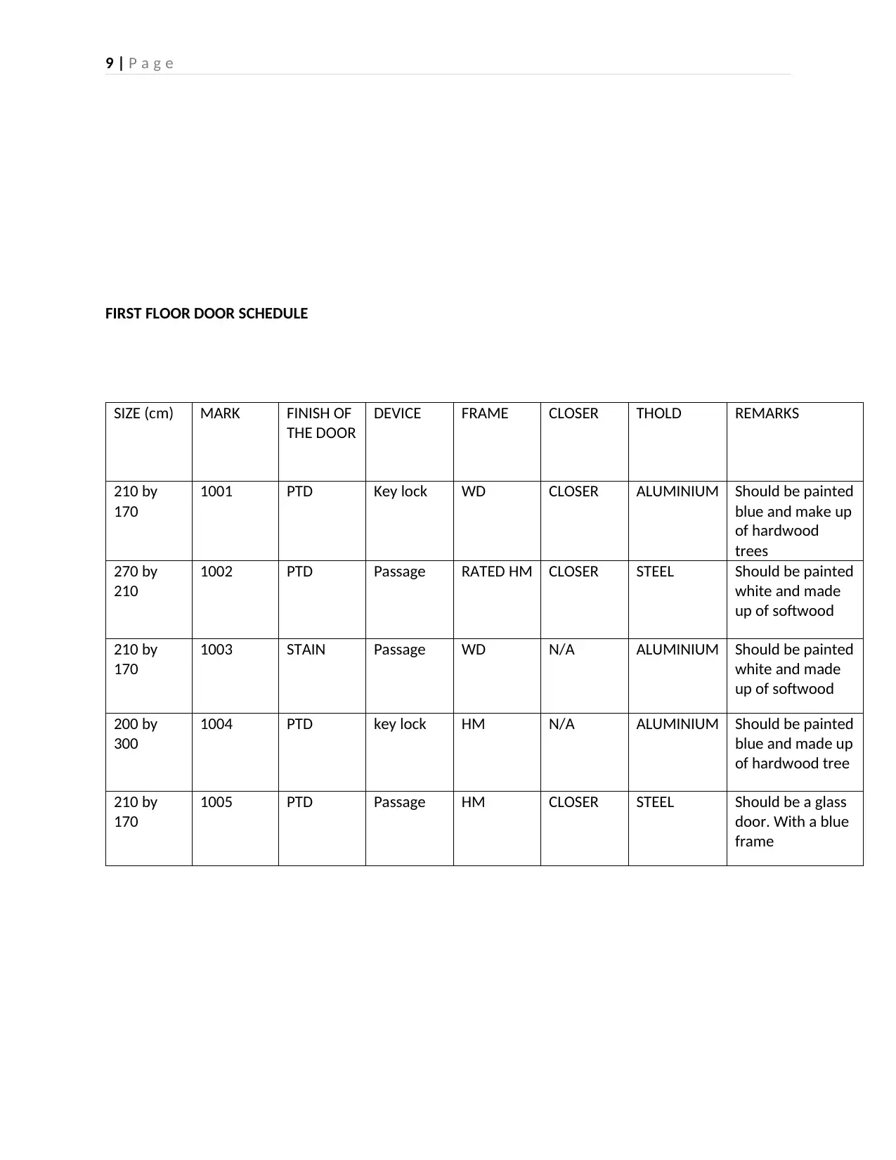
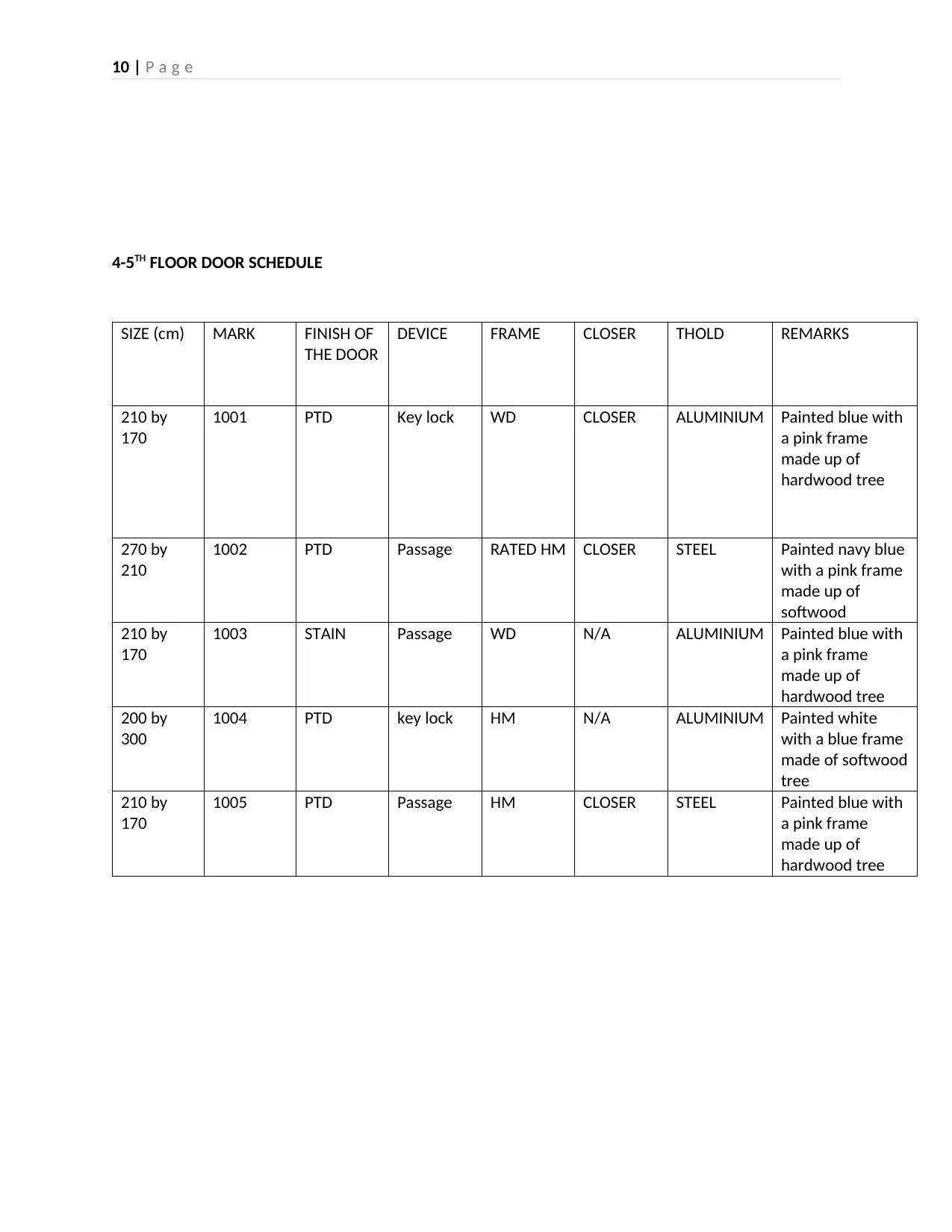
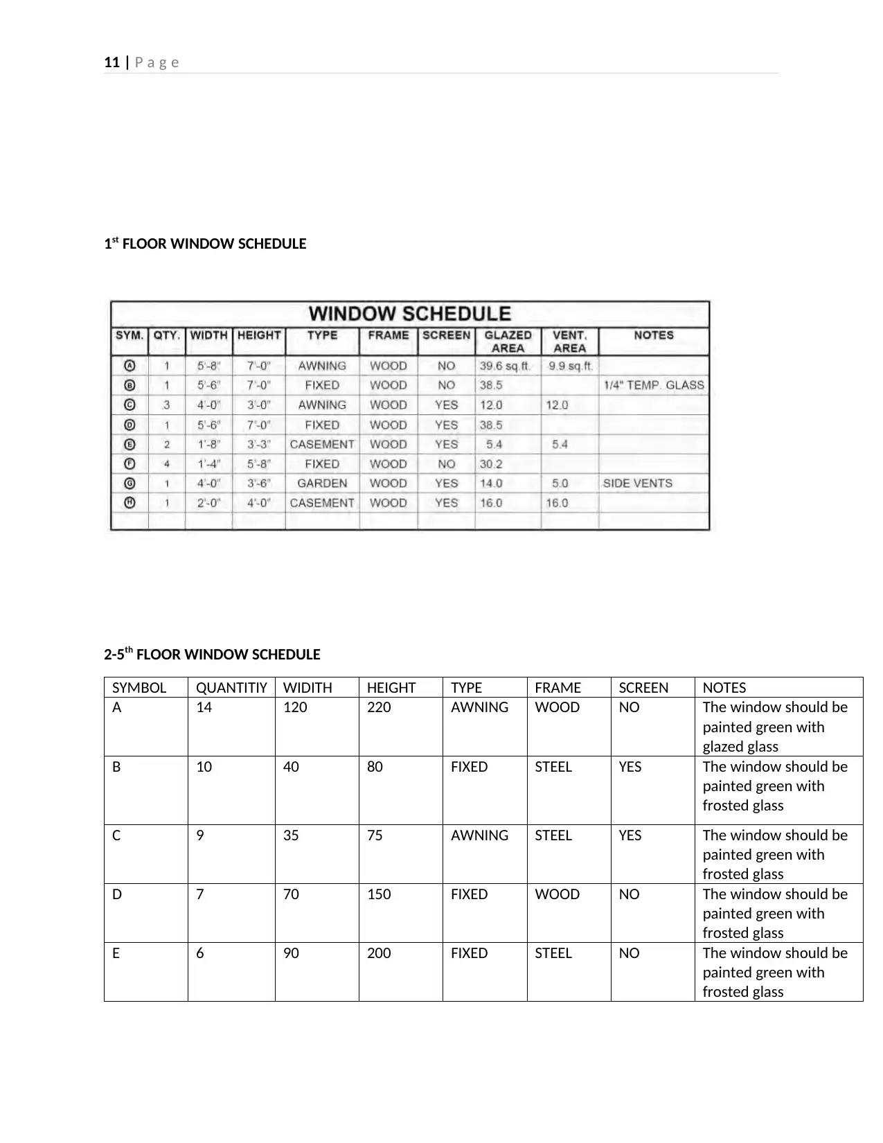
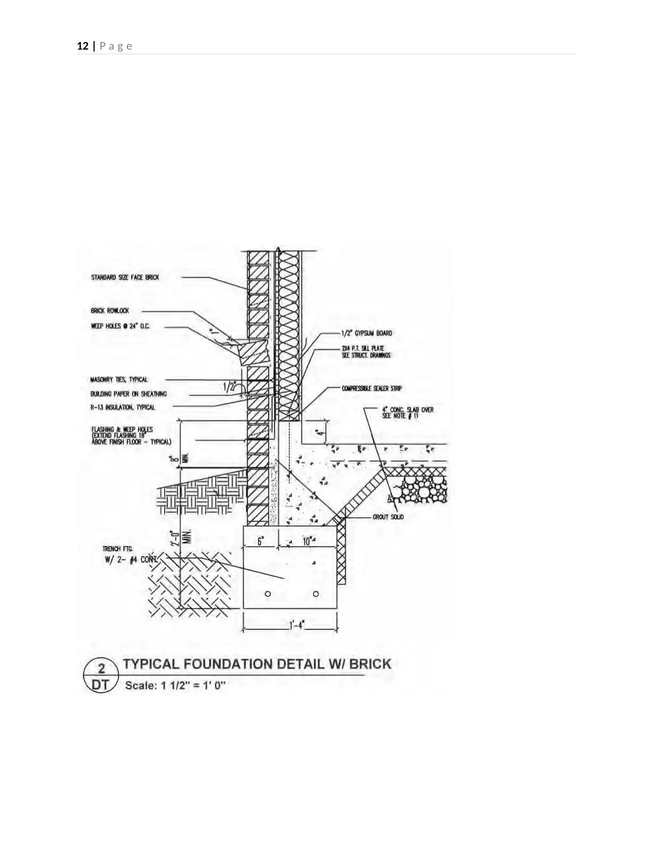
This report comprehensively examines construction information within the context of a construction project. It begins by categorizing different types of construction information, including concept, presentation, and working drawings, and their respective purposes. The report then delves into various construction drawings such as site plans, floor plans, elevations, and detailed schedules for doors and windows, illustrating their significance in the construction process. Furthermore, the report explores different types of specifications used in construction projects, including performance, description, and proprietary specifications, along with the factors influencing their selection. It also discusses the importance of identifying and addressing errors and clashes in construction information, detailing clash detection software such as BIM and Revit. Finally, the report concludes with critiques of construction information, emphasizing the need for clear, concise, and unambiguous language in specifications and drawings to ensure effective communication and minimize potential issues during construction. This report is a valuable resource for students seeking to understand the complexities of construction information management.

1 | P a g e
TITLE: CONSTRUCTION INFORMATION (DRAWING, DETAILING AND SPECIFICATION)
ACADEMIC YEAR: 2017-18 UNIT
TUTOR: DR SHAHAB SAMAD
ASSIGNMENT TITLE: CONSTRUCTION INFORMATION PRODUCTION
DATE OF ISSUE: 19th FEBRAURY ,2019
SUBMISSION DATE :11th MAY ,2019
STUDENT NAME:
TITLE: CONSTRUCTION INFORMATION (DRAWING, DETAILING AND SPECIFICATION)
ACADEMIC YEAR: 2017-18 UNIT
TUTOR: DR SHAHAB SAMAD
ASSIGNMENT TITLE: CONSTRUCTION INFORMATION PRODUCTION
DATE OF ISSUE: 19th FEBRAURY ,2019
SUBMISSION DATE :11th MAY ,2019
STUDENT NAME:
Secure Best Marks with AI Grader
Need help grading? Try our AI Grader for instant feedback on your assignments.

2 | P a g e
1. Different types of construction information used in diverse project types.
Construction information always provide accurate construction drawings which ensure that the
construction projects will continue in the way which is intended, it always reduces the cost and the time
required by the contractors in the project. Construction drawing are categorized according to their
purpose in construction.
kind of drawing mostly used in construction information are divided into three categories based on the
purpose they serve:
1. working drawings
2. Presentation drawings
3.preliminaray drawings
1. Concept Drawings
This are drawings which are used in early stages of designing a building by providing a workspace for
sketches development. The sketches are very useful tool since they work as a medium for
communication between the client and the constructor. The pros of having a sketch is that it can
undergo a lot of changes to determine the type of building which the client find most beautiful and
desirable. These drawings are not always meant for construction purpose but they act as a tool to
explain and discuss client’s needs. They are not very detailed and therefore are easy to understand since
they just display the general picture of the building. Sometimes the concept drawing may also be used in
explaining different system in the building and how the installation process may be carried out. The
systems may include plumbing and electrical installations.
2. Presentation Drawings
This are types of drawing which show the level of attractiveness of the proposed building. It shows the
outside layout and furnishing of the building. Due to this this document has been very vital in
advertisement of the building and therefore it has become one of the most important selling tools in the
modern days. For this drawings to be rendered beautiful they must include different color and show
different levels of shading for the building to attain a realistic look. Furthermore, they may also go a mile
higher by including elevation views containing shadows and the landscaping of the building. Recently
presentation drawing have been evolving and brochures and other outlets are now considered.
3.working drawings
They are drawings used by tradespersons to compete for the building project. These drawings show the
meaningful information required by the constructor. The drawings may be completely defined by the
how complex the overall construction process is. Generally, the most complex projects will require a lot
of construction data to avoid any instances of confusion by those undertaking the project. It is also
important to note that most construction drawings consist of orthographic views which ensures that the
building in viewed in a proper manner. There are also General drawings which consist of plans and
elevations drawn at a relatively small scale, and Detail drawings which consist of sections and details
drawn at a relatively large scale.

3 | P a g e
Plan view
A plan view is the vision generated when an area or a building is projected in a horizontal plane. There
different types of plan views they include foundation plans, floor plans, plot plans and framing plans1.
The plan view shows significant feature of an area which are rendered useful by the constructor. The
may include the geographical positioning of the area. The geography of the area may be determined by
the contour of the area, altitude, physical feature such as mountains and other feature such as trees and
the surrounding area vegetation. The reference point of the area is always selected and important data
from the construction site is then extracted. This data provides an important information for the
excavator who had interest in the project.
The major purpose of documenting construction drawing include:
•They work as Instruments for material take-offs
• They provide procedure to be followed during construction.
• They act as a Means for granting a construction permit: Before construction can begin, the
local building parties must check the working drawings to see that they have met the
requirements
• They are used for competitive bidding.by this they allow the potential contractors a uniform
guide for preparing bids, therefore providing the owner a way of reducing the building costs.
• They act as a means of coordinating trade: Working drawings provide a good rapport between
material suppliers and specialized trades.
•They eliminate remeasurements in case of future reconstruction. This is achieved by ensuring
that the Drawings are furnished in case of legal disputes.
• They define the agreement between owner and tenant: In leasing of a building, the owner
must use the working drawings in the contract agreement
.
1Building and construction illustrated John Wesley and sons 2014

4 | P a g e
2. construction drawings, details, schedules and specifications used in the construction project.
The following are various construction drawing which are very useful during construction they show
different angles of the building so that the constructor will not have any difficulties during the building
process
Site plan (scale 1:500)
Secure Best Marks with AI Grader
Need help grading? Try our AI Grader for instant feedback on your assignments.

5 | P a g e
Scale 1:500
Floor plan
Scale 1:500
Floor plan

6 | P a g e
scale1:500
scale1:500

7 | P a g e
Side elevation
Scale1:500
Side elevation
Scale1:500
Paraphrase This Document
Need a fresh take? Get an instant paraphrase of this document with our AI Paraphraser

8 | P a g e
Front elevation(scale 1:500)

9 | P a g e
FIRST FLOOR DOOR SCHEDULE
SIZE (cm) MARK FINISH OF
THE DOOR
DEVICE FRAME CLOSER THOLD REMARKS
210 by
170
1001 PTD Key lock WD CLOSER ALUMINIUM Should be painted
blue and make up
of hardwood
trees
270 by
210
1002 PTD Passage RATED HM CLOSER STEEL Should be painted
white and made
up of softwood
210 by
170
1003 STAIN Passage WD N/A ALUMINIUM Should be painted
white and made
up of softwood
200 by
300
1004 PTD key lock HM N/A ALUMINIUM Should be painted
blue and made up
of hardwood tree
210 by
170
1005 PTD Passage HM CLOSER STEEL Should be a glass
door. With a blue
frame

10 | P a g e
4-5TH FLOOR DOOR SCHEDULE
SIZE (cm) MARK FINISH OF
THE DOOR
DEVICE FRAME CLOSER THOLD REMARKS
210 by
170
1001 PTD Key lock WD CLOSER ALUMINIUM Painted blue with
a pink frame
made up of
hardwood tree
270 by
210
1002 PTD Passage RATED HM CLOSER STEEL Painted navy blue
with a pink frame
made up of
softwood
210 by
170
1003 STAIN Passage WD N/A ALUMINIUM Painted blue with
a pink frame
made up of
hardwood tree
200 by
300
1004 PTD key lock HM N/A ALUMINIUM Painted white
with a blue frame
made of softwood
tree
210 by
170
1005 PTD Passage HM CLOSER STEEL Painted blue with
a pink frame
made up of
hardwood tree
Secure Best Marks with AI Grader
Need help grading? Try our AI Grader for instant feedback on your assignments.

11 | P a g e
1st FLOOR WINDOW SCHEDULE
2-5th FLOOR WINDOW SCHEDULE
SYMBOL QUANTITIY WIDITH HEIGHT TYPE FRAME SCREEN NOTES
A 14 120 220 AWNING WOOD NO The window should be
painted green with
glazed glass
B 10 40 80 FIXED STEEL YES The window should be
painted green with
frosted glass
C 9 35 75 AWNING STEEL YES The window should be
painted green with
frosted glass
D 7 70 150 FIXED WOOD NO The window should be
painted green with
frosted glass
E 6 90 200 FIXED STEEL NO The window should be
painted green with
frosted glass

12 | P a g e

13 | P a g e
3. Different types of construction information used to explain a construction project
(i)specifications. This is a document which shows essential requirement of goods and services required
by the client. They are mostly used to complement construction drawing by providing information which
is not able to explained in the drawing. This information may be used in procurement and assignment of
contract to different individuals involved.
(i) performance specifications,
(ii)description specifications
(iii) proprietary specifications
(iv)reference-standards specifications.
There are several factors determining which specification is used as discussed below.
Closed specification.
This is a type of specification which shows product, systems and the constructor with no mechanisms of
applying a substitution. This kind of specification is usually used when matching a specification to a
building which had existed earlier. Originally this kind of closed specification are considered
proprietary2.But the specification can be made open when there are written with an aim of not referring
to a particular brand or providing requirements which are only applicable to a single and specific
product. This is usually done by adding the clause “or equal” after the listed brand.it is also important
for the manufacturers to always have knowledge of various classifications and types of specification
used in construction.
Open Specification
This kind of specification gives the contractor choice for him/her to achieve the desired results. The
copies of specification mostly are given free of charge to the clients and a moderate fee is implemented
under discriminatory licensing and by all the parties which are interested. Open specifications have
proved to be very advantageous in the following ways.
(i)It has created healthy competition in the building market, manufactures and supplier can therefore
compete on a level ground.
2 Building and construction handbook Routledge construction 2016
Paraphrase This Document
Need a fresh take? Get an instant paraphrase of this document with our AI Paraphraser

14 | P a g e
(ii)It has eliminated any instances of trade restrictions; therefore, any specifier can apply materials
satisfying the open specification.
(iii)Supply of materials has really improved and therefore the work progress does not suffer.
(iv)There have been also reduction of transportation cost and the time used in service delivery.
Therefore, it can be concluded that open specification is very vital in construction project and a
constructor who does not use them is subjected to a lot of difficulties which may compromise quality
delivery.
Identification of errors and clashes
A clash usually takes place when elements of different systems or models occupies the same position.
The clash may be geometric, schedule based or changes/updates that have not been made to the
drawing. There has been development of different software of clashes detection including BIM and
Revit. This software has made detection of hard and soft clashes easier. Hard clashes can be very
destructive to the building process. This is because the work schedules may be affected, this may cause
workers arriving to the construction site without any working tools, also it may cause confusion during
building process. If this incoordination continues it may cause injuries to the worker or create unhealthy
working environment.
If the clashes in the drawing are implemented the construction process might be uneconomical due to
wastage of materials and labor. This may also affect the necessary time required to complete the
building hence massive losses.
Errors and discrepancies encountered in evaluation of construction information.
(i)The specification should embrace the use of the current standards used in building technology and
the methods used should be applicable.

15 | P a g e
(ii)specification which are easier to implement should be used and the ambiguous ones should be
avoided at all costs.
(iii) Don’t specify standards that cannot be measured.
(iv) The specification is supposed to be clear and easy to understand simple statement are supposed to
be used frequently throughout the document.
(v) one should always avoid unnecessary uses of exculpatory clauses.
(vi) specification should be shorter and brief as possible.
(vii) correct Capitalization of major parties of the document should be done.
(viii) one should understand that shall show a command while will is used when one has a choice.
(ix) same terminology should be used in drawings and specifications documents
Critiques of body of construction information,
(i) The language used in specification3 must be precise, the text should not be inadequate or ambiguous
since it will create confusion during construction process.
(ii) Drawings should show information that can be most efficiently represented in graphs by means of
drawings/ diagrams.
(iii) The specifications should show kind of information which is normally easier to display such the
procedure to be followed, standards, guarantees and the names of those involved.
(iv) construction information drawings should be used to express quantity. While specifications should
be used to describe quality.
(v) Drawings should show the type of material example, wood, steel etc. while specifications should
clarify the species e.g. oak, cider.
Industrial standard notation
There have been different organizations which have raised up to set standards used in construction and
engineering. Their main objective includes:
(i) Providing information and access to reach the world standard example is ANSI
(ii) Advancing the arts and sciences of heating, ventilation and air-conditioning to the public
benefit example is AHRAE
3 John Wiley the CSI construction specification practice guide sons 2016

16 | P a g e
(iii) Development and publication of voluntary consensus of materials and products. Example is
ASTM
(iv) providing fire, electrical, and life-safety information to the public an example is NFPA.
(v) maintaining and operating labs around the world for the testing and examination of devices,
systems, and materials an example is UL4 .
Corrections of construction drawings
A construction drawing must show a correct linear perspective of the building this ensures that the
dimension is properly placed and there is good estimation of distance. Also the drawing should also be
able to show the correct vertical alignment of the structures, this ensure there is no illusion in the
dimensioning process.
4.collaborations of professionals in production of construction information.
How different bodies of information work in conjunction
There are many document which are used in construction information. This documents are supposed to
correlate each other. The specifications should show details which are not able to be presented in the
working drawing. On the other hand, the working drawing should contain all elevation and detailing that
will ensure that the contractor has an easier time in understanding the building. The dimension should
be presented in the required scale which ensures that most of the building can be seen on the drawing
sheet. Apart from having the appropriate document presentation the industrial board must also ensure
that standards are followed.
There are different ways in which construction professional collaborate, one of the ways is by setting
industrial standard which must be followed by every constructor. The professionals have set different
boards which ensures that the engineering standards are not assumed. One of those standard is the ISO
standard and the ANSI standard. Most of the engineering project follow this standard to ensure
uniformity and quality assurance of the construction project.
Also the professionals have come up with different industrial standard software such as AUTOCAD and
BIM which ensure that the construction drawing are of good standard and presentable. Although CAD
and BIM have different uses in the industry as discussed below. They have proven to be very useful soft
wares in construction industry. 5
CAD
4 Understanding construction drawing Delmar Cengage 2009.
5 Kalen M and Weygand, RS construction specification writing john Wiley and sons 2011
Secure Best Marks with AI Grader
Need help grading? Try our AI Grader for instant feedback on your assignments.

17 | P a g e
This is a software which is used in construction and engineering to meet the layout and the installation
requirements. Many engineers and architects are embracing this technology for drawing layout of
buildings and structures. CAD has many advantages compared to the traditional methods of drawing
which were tiresome and time consuming. But with the help of this software the construction drawing
has been simplified. CAD software integrates different software which are used in accounting and
scheduling work during construction. These modern tool significantly reduces the errors which might be
encountered.6
Building Information Modeling (BIM)
This is a software package which provides energy modeling based on criteria input rater, such as blower
door and duct blaster testing, quality of installation, insulation quantity and cooling and heating
equipment. By the use of BIM software one can provide a detailed analysis to the owner of the building.
Also, one can show the operating costs and operation efficiencies in the building layout.
Apart from assisting in construction and design process BIM is also essential in minimizing instances of
clashing during building process. It can detect instances of hard and soft clashes which will thereafter be
corrected by the constructor of the building.
BIBLIOGRAPHY
[1] CHING, F.D.K. BUILDING CONSTRUCTION ILLUSTRATED. John Wiley & Sons 2014.
[2] CHUDLEY, R. BUILDING AND CONSTRUCTION HANDBOOK. Routledge Construction 2016
[3] JOHN WILEY THE CSI CONSTRUCTION SPECIFICATION PRACTISE GUIDE Sons 2011
[4] HUTH, M.W. UNDERSTANDING CONSTRUCTION DRAWING. Delmar Cengage 2009.
[5] KALIN, M. and WEYGANT, R.S. CONSTRUCTION SPECIFICATION WRITING John Wiley & Sons 2011.
[6] KUBBA, S. BLUEPRINT READING: Construction Drawing for the Building Trade. McGraw-Hill 2008.
6 Kubba, blueprint reading: construction drawing for the building trade. McGraw-Hill 2008

18 | P a g e
1 out of 18
Related Documents

Your All-in-One AI-Powered Toolkit for Academic Success.
 +13062052269
info@desklib.com
Available 24*7 on WhatsApp / Email
Unlock your academic potential
© 2024  |  Zucol Services PVT LTD  |  All rights reserved.