Construction Technology 6 – Hydraulics 2: Water Supply Design

Verified

Added on  2023/01/17

|8
|979
|32
Practical Assignment
AI Summary
This assignment focuses on the design of water supply and drainage systems for a proposed office development in Maitland, NSW. It begins by determining water storage requirements based on occupancy and floor area, calculating daily water consumption, and specifying the use of underground and roof storage tanks. The solution includes detailed calculations for pipe sizing, considering flow rates, loading units, and pressure set capacity. The assignment also addresses roof drainage, utilizing the Simplified Rational Method to determine flow rates and downpipe requirements. Furthermore, it covers sanitary plumbing and drainage, detailing discharge units, branch pipe determination, and the sizing of drainage stack pipes. The solution provided includes a single-line diagram and calculations for an on-site detention (OSD) system, determining its capacity based on rainfall intensity and allowable runoff. The assignment adheres to relevant standards and codes, including AS 3500, and provides a comprehensive overview of hydraulic services design for the office building.
Document Page
Construction Technology 6 – Hydraulics 1
CONSTRUCTION TECHNOLOGY 6 – HYDRAULICS
Student’s Name
Course
Professor’s Name
Institutional Affiliation
City
Date
tabler-icon-diamond-filled.svg

Paraphrase This Document

Need a fresh take? Get an instant paraphrase of this document with our AI Paraphraser
Document Page
Construction Technology 6 – Hydraulics 2
1) Cold Water Supply System
In an office development, water storage requirement is based on the occupancy per net floor
area. Occupancy is based on the floor area. In this proposed office block, the total lettable areas
are as shown in table 1 below.
Table 1: Floor areas for the proposed office building
Office level Tenant (Lettable) floor area (SQM)
Ground floor 1083
Level 1 869
Level 2 700
Level 3 496
Total 3148
Water consumption is assumed to be 900 litres per day for an office space per 100m2
lettable area.
Cold water requirement per day= 3148
100 × 900 litres
¿ 28,8332litre s
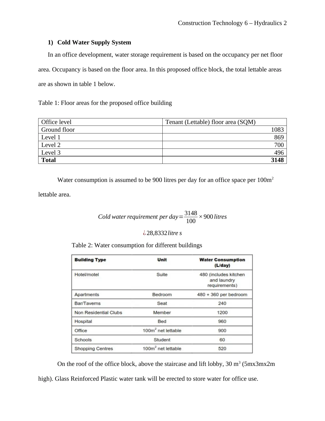
Table 2: Water consumption for different buildings
On the roof of the office block, above the staircase and lift lobby, 30 m3 (5mx3mx2m
high). Glass Reinforced Plastic water tank will be erected to store water for office use.
Document Page
Construction Technology 6 – Hydraulics 3
Since the water from the local authority supply is at 210 kPa (2.1 bar), there is a need for an
underground water storage tank. This is because the pressure is low to pressurize to the roof
storage tank and to the faucets and appliances in the office block. The underground tank is
located in basement 2 and its capacity allows for 3 days storage. The tank is GRP type of
capacity 80 m3 (8mx5mx2m high)
a) The pipework layout has been shown in the plan layout with mains from the authority
supplying to the underground tank from where the booster pumps pressurize to the roof
storage tank as well as branching to the office wet areas and kitchenettes. From the roof
tank, the water flows via gravity to the office spaces.
The main riser pipe from the underground water tank is made from Galvanized Mild
Steel (GMS). These pipes are efficient in high pressure application. Internal reticulation
to the office wet areas and kitchenettes is done in PPR pipes which are more flexible in
use.
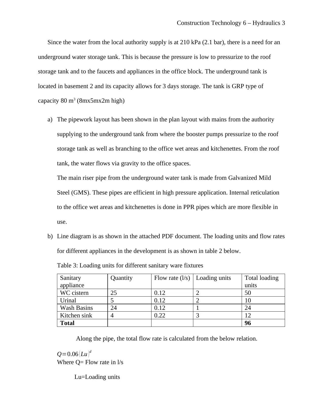
b) Line diagram is as shown in the attached PDF document. The loading units and flow rates
for different appliances in the development is as shown in table 2 below.
Table 3: Loading units for different sanitary ware fixtures
Sanitary
appliance
Quantity Flow rate (l/s) Loading units Total loading
units
WC cistern 25 0.12 2 50
Urinal 5 0.12 2 10
Wash Basins 24 0.12 1 24
Kitchen sink 4 0.22 3 12
Total 96
Along the pipe, the total flow rate is calculated from the below relation.
Q=0.06 ( Lu ) d
Where Q= Flow rate in l/s
Lu=Loading units
Document Page
Construction Technology 6 – Hydraulics 4
d=Diversity factor (63.5%)
Therefore;
Q=0.06 ( 9 6 ) 0.635
¿ 1.07 l /s
Pipe sizing is dependent of the velocity of water flow as well as the flow rate as
given in the relation below.
Internal Diameter (ID )=35.68 Q
V
Where;
Q= Flow rate (l/s)
V= Velocity of flow (Usually 1.6 m/s)
Therefore;
ID=35.68 1.07
1.6
ID=29.17 mm
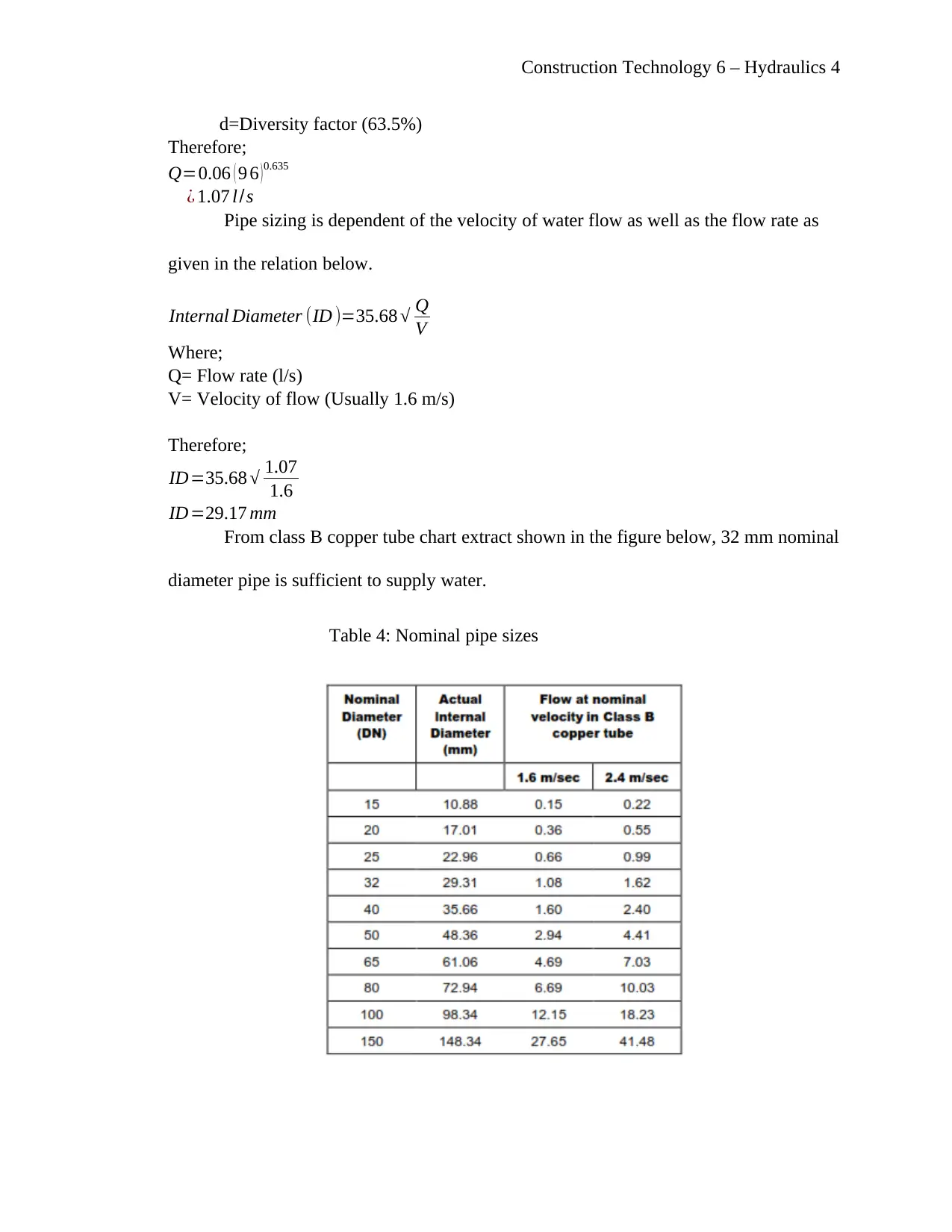
From class B copper tube chart extract shown in the figure below, 32 mm nominal
diameter pipe is sufficient to supply water.
Table 4: Nominal pipe sizes
tabler-icon-diamond-filled.svg

Paraphrase This Document

Need a fresh take? Get an instant paraphrase of this document with our AI Paraphraser
Document Page
Construction Technology 6 – Hydraulics 5
Water supply to individual sanitary appliance will be done in 25mm nominal
diameter as this will be efficient for each appliance flow and velocity requirements.
c) Pressure set capacity
This is attributed by head losses due to friction, losses in fittings, elevation
changes, and head gains due to pumps.
Friction head loss
hf =f [ ( L V 2 ) / ( 2 gd ) ]
where;
hf = head loss due to friction (m)
f =friction factor (0.075)
L=eeffective length (m)
V =velocity (m/s)
g=gravity (9.81 m/s/s
d= internal diameter (m)
h f =0.075 [ ( 50 ×1.62 ) / ( 2× 9.81× 0.032 ) ]
h f =15 m
Head Loss Due to Fittings
hf =k ( V 2 /2 g )
where;
hf = head loss due to fittings (m)
k =fitting loss coefficient (1)
V =velocity (m/s)
g=gravity (9.81 m/s/s
hf =1 ( 1.62 /2 × 9.81 )
hf =0.1 m
Document Page
Construction Technology 6 – Hydraulics 6
Head Loss Due to height of the building
Vertical height of the building=25m
Total head is given by the sum of the above;
Friction head loss + Head Loss Due to Fittings + Head Loss Due to height of the building
¿ 15 m+0.1 m+25 m
¿ 40.1 m(410 kPa)
Pressure set capacity should be at least 1.07 l/s (3.85 m3/hr.) at 40.1 m head.
2) Roof Areas Drainage
a) Assumptions
Storm Intensity Calculations
Roof drainage design is a function of roof area and rainfall intensity. In Maitland,
rainfall intensity is estimated to be 50mm/hr.
Flow rate is calculated from the following relation;
Q=( Roof Area × Rainfall intensity × Runoff coefficient /3600)
Q=¿
Q=77 l/ s
This flow rate will be drained by 17Nos 100mm PVC downpipes each of flow
capacity of 4.6l/s.
b) Sigle line diagram
The line diagram is shown in the PDF document attached.
c) The OSD size is based on an hour’s downpour at a rate of 80l/s per ha.
Therefore, for 0.154 ha, the amount of water to be collected will be given by the
following relation;
Capacity=0.154 × 80l/ s ×3600 sec
Document Page
Construction Technology 6 – Hydraulics 7
Capacity=44,352 litres
The approximate capacity of the OSD pit is 48 cubic metres (6mx4mx2m high)
3) Sanitary Plumbing and Drainage System
a) Pipework sizing.
The drainage stack pipe sizing is based on the discharge units from sanitary
fixtures.
Table 5: Discharge units for sanitary fixtures
Sanitary fixture Quantity Discharge unit Total discharge
units
WC 24 14 336
Urinal Bowls 5 0.3 1.5
Wash Basins 24 3 72
Kitchen Sink 4 14 56
Total 465.5
Branch determination is based on the type of drainage system used. In this case,
single stack system is used with one stack and soil vent pipe. Branch pipes are as per
the Australian Standard AS 3500 part two as shown in the figure below.
tabler-icon-diamond-filled.svg

Paraphrase This Document

Need a fresh take? Get an instant paraphrase of this document with our AI Paraphraser
Document Page
Construction Technology 6 – Hydraulics 8
Table 5: Branch pipes
b) Sigle line diagram
The single line diagram is shown in the PDF attached.
chevron_up_icon
1 out of 8
circle_padding
hide_on_mobile
zoom_out_icon
[object Object]