Construction Management Plan for Bridge Replacement - EGB382
VerifiedAdded on 2023/04/06
|50
|7407
|55
Report
AI Summary
This report presents a construction management plan for a bridge replacement project, including 2km of approach resurfacing. It outlines early works such as site clearance and establishment, demolition work, and pile driving. The report details substructure construction (abutments and roadwork) and superstructure construction (headstock and deck), including required equipment and materials. A Gantt chart provides a timeline, and a worksite sketch illustrates the layout. The plan also includes an environmental management plan, construction staging, traffic control measures, and an emergency response plan. This document, contributed by a student, is available on Desklib, which offers a wide range of study resources including past papers and solved assignments.
1
CONSTRUCTION METHODOLOGIES
By Name
Course
Instructor
Institution
Location
Date
CONSTRUCTION METHODOLOGIES
By Name
Course
Instructor
Institution
Location
Date
Paraphrase This Document
Need a fresh take? Get an instant paraphrase of this document with our AI Paraphraser
2
TABLE OF CONTENTS
List of figures...................................................................................................................................2
INTRODUCTION....................................................................................................................2
Project description...........................................................................................................................2
PROJECT OUTLINE...............................................................................................................2
Early works......................................................................................................................................2
Site clearance...................................................................................................................................2
Site establishment............................................................................................................................3
Demolition work..............................................................................................................................5
Pile driving.......................................................................................................................................6
Substructures (abutment, roadwork)................................................................................................7
Abutment form and construction.....................................................................................................7
Abutment form.................................................................................................................................7
Abutment layout..............................................................................................................................8
Abutment construction.....................................................................................................................9
Road works....................................................................................................................................10
Superstructures (headstock, deck).................................................................................................13
REQUIRED MAJOR EQUIPMENT.....................................................................................13
MATERIAL USED IN BRIDGE CONSTRUCTION...........................................................16
GANTT CHART....................................................................................................................22
WORKSITE SKETCH...........................................................................................................24
ENVIRONMENTAL MANAGEMENT PLAN....................................................................24
Introduction....................................................................................................................................24
Materials and methods...................................................................................................................25
Ecological impact..........................................................................................................................25
3
Physical-chemical impacts.............................................................................................................26
Human impact................................................................................................................................26
CONSTRUCTION STAGING...............................................................................................27
Clearing and Excavation................................................................................................................27
Site establishment..........................................................................................................................28
Construction of the foundation......................................................................................................28
Construction of supports................................................................................................................29
Assembly and introduction of the superstructure..........................................................................30
Pouring the slab.............................................................................................................................30
Bridge finishes...............................................................................................................................30
TRAFFIC CONTROL............................................................................................................31
Illumination and reflection............................................................................................................31
Position of the road signs...............................................................................................................31
Erection of the signs......................................................................................................................31
Traffic control plans......................................................................................................................33
EMERGENCY RESPONSE PLAN.......................................................................................35
Hazard assessment/ identification..................................................................................................36
Emergency resources.....................................................................................................................37
Communication Systems...............................................................................................................38
Administration of the plan.............................................................................................................38
Emergency Response Procedure....................................................................................................39
Debriefing and Post-Traumatic Stress Procedure..........................................................................40
Conclusion..............................................................................................................................41
References..............................................................................................................................41
⊘ This is a preview!⊘
Do you want full access?
Subscribe today to unlock all pages.
Trusted by 1+ million students worldwide
4
List of figures
Fig 1: portable toilet.........................................................................................................................6
Fig 2: Plans of the two commonly used abutment forms: a) wing-wall abutment form b) spill-
through abutment form..................................................................................................................10
Fig 3: Abutment layout..................................................................................................................11
Fig 4: Embankment geometry.......................................................................................................12
Fig 5: Army asphalt distributor......................................................................................................13
Fig 6: Towed aggregate spreader...................................................................................................14
Fig 7: Asphalt meal........................................................................................................................14
Fig 8: Asphalt kettle.......................................................................................................................15
Fig 9: Site sketch...........................................................................................................................27
Paraphrase This Document
Need a fresh take? Get an instant paraphrase of this document with our AI Paraphraser
5
INTRODUCTION
Project description
Highway bridges are very important components of any government’s transportation
network, bridges have received a lot of focus from government agencies , since they are the
key elements of the nation's transportation system because they control the capacity of the
transportation system, because the bridges are the highest cost per mile of the system and
because if bridges fail all the highways system fails (Mallett, 2018).
The project will involve bridge replacement, including 2km approach resurfacing on each side,
the bridge replacement will remove the existing structurally deficit culvert box. The project will
also involve the restoration of the stream geomorphology, enhancement of the overall ecological
function and the enhancement of the fish habitat and passage. This report will focus on
Developing a Construction Program for the bridge replacement, Development of a Construction
Traffic and Access Management Plan and Formwork design (Tadros, 2012).
PROJECT OUTLINE
Early works
This will involve the following:
Site clearance
This is the activities that will be carried out to prepare the site for the replacement of the bridge
and resurfacing of the 2km road. The process will involve clearing the site of any equipment or
machinery, rubbish, unwanted or surplus materials among others. The site clearance will also
involve clearing away the available surface soil and vegetation and leveling and preparing the
ground for the planned bridge replacement. A lot of care should be taken to ensure that there are
6
correct approvals being put in place, especially for trees and another type of vegetation which
will require protection (Mattew, 2016).
During site clearance, site waste management will be prepared prior to the commencement of
site clearance. The plan will describe how the materials will be managed effectively and
disposed of legally, explaining how the recycling and re-use of the construction material will be
maximized. Different types of wastes available on the site will be removed efficiently and safely.
In case of any contaminated waste or potentially hazardous substances such as asbestos,
professional will be consulted and come up with ways on how they handle them carefully
(Administration, 2014).
Site establishment
An effective and efficient site establishment offers the foundation for successful project delivery,
organizing and structuring the temporary facilities required to support replacement and road
resurfacing. While a small construction project is known to require a small temporary site
establishment, large projects such as bridge replacement may need extensive site infrastructure.
Before the resurfacing of the 2Km road and the replacement of the bridge, it will be very
important to have a site establishment checklist.The checklist will be very important in preparing
the site before the start of the construction works. The site checklist will include and not limited
to:
i) Site amenities
This is the facilities that will be provided at the site to ensure that the construction activities run
smoothly and they will include; site sheds, toilets, tool lockups, running water, lunch rooms, etc.
⊘ This is a preview!⊘
Do you want full access?
Subscribe today to unlock all pages.
Trusted by 1+ million students worldwide
7
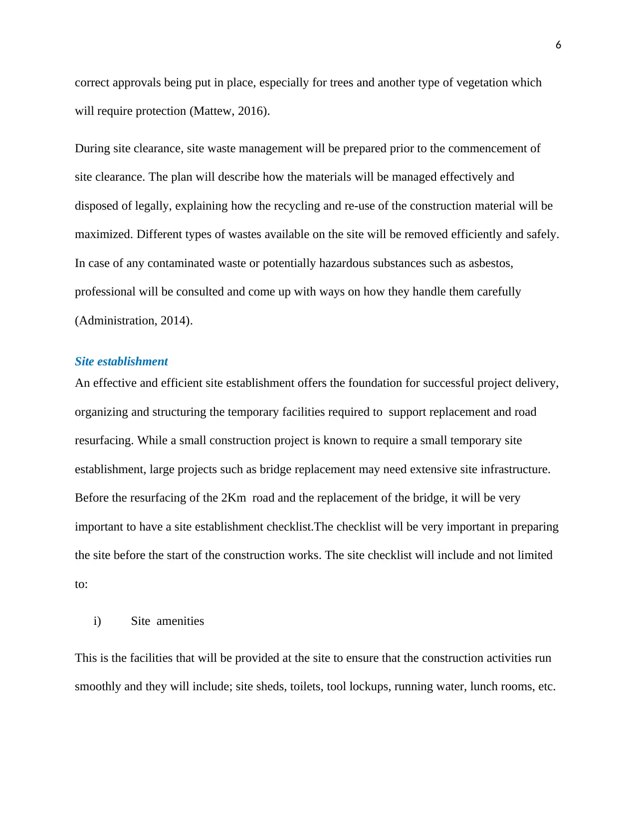
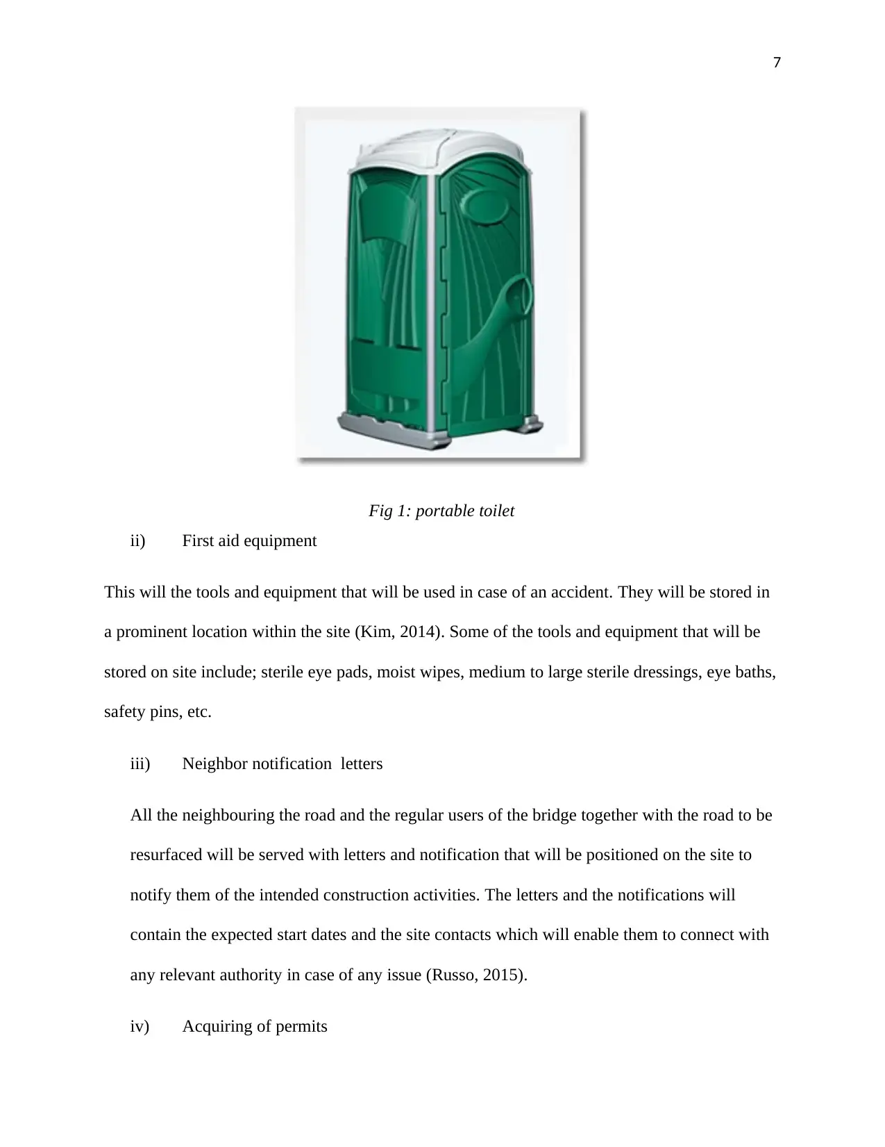
Fig 1: portable toilet
ii) First aid equipment
This will the tools and equipment that will be used in case of an accident. They will be stored in
a prominent location within the site (Kim, 2014). Some of the tools and equipment that will be
stored on site include; sterile eye pads, moist wipes, medium to large sterile dressings, eye baths,
safety pins, etc.
iii) Neighbor notification letters
All the neighbouring the road and the regular users of the bridge together with the road to be
resurfaced will be served with letters and notification that will be positioned on the site to
notify them of the intended construction activities. The letters and the notifications will
contain the expected start dates and the site contacts which will enable them to connect with
any relevant authority in case of any issue (Russo, 2015).
iv) Acquiring of permits
Paraphrase This Document
Need a fresh take? Get an instant paraphrase of this document with our AI Paraphraser
8
There will need to obtain al relevant permits before the commencement of the construction
works. The permits will include items such as work zones, skip bins and traffic control items
Demolition work
Bridge demolition work will be the most technical work to be carried out in this project. It will
caution and a lot of care in order to ensure that very little debris will escape onto the roads and
the river below, as well as the protection of the site workers. Below, are different materials and
components included in the construction of a bridge that requires different methods and
approaches for demolition (Pritchard, 2017).
Bridge demolition methods
i) Hydraulic breakers
This technique makes application of boom-mounted breakers to break apart the bridge
components and materials and it can be adapted to undertake underwater demolition of bridges
for the abutments and supports. This method creates a lot off debris, noise, vibrations, and dust.
ii) dismantling
This technique usually involves cutting a bridge into sections and removing them one by one
using cranes. Using water-jetting, thermal lances, and sawing, the bridge can be cut into sections
and then disposed of without production of dust and noise (McCahon, 2018).
iii) Bursting
Three are three different types of bursting that are used in the bridge demolition i.e. mechanical,
chemical and pressure bursting. Each type, despite using a different technique, uses some kind of
pressure to force the concrete to break and split. All three methods do not produce noise nor dust.
9
Pile driving
The piles for the bridge replacement will be driven cast-in-situ piles. In this approach, a steel
casing piles with a shoe at the bottom is first driven to the required depth. The reinforcement
cage for reinforcing is then lowered inside the casting and then concrete is poured inside. As the
concrete continues to fill the pile cage, the casing is withdrawn keeping a suitable overlapping
length (Brown, 2018). The moment such piles will be driven in soft soil and the tube is
withdrawn when the concrete is being poured it will affect the resistance and then change the
property of the soil and this also will have a great impact on the capacity of the individual piles.
Also, bored cast-in-situ piles will also be used. In this type of driving piles into the ground a
casing with a large diameter is used. Usual a casing with approximately 3 to 4 meters in length
will be provided on top of the hole which will be driven with the aid of a boiler. Boring much
further below this given casing will be carried out through chiseling at the same time the side
walls will be kept stable by circulating betonies slurry inside the hole. After reaching the desired
level where the ground is stable, the chisel will be removed, the resulting hole will be flushed,
the reinforcement cage will then be lowered into the hole and it will be held in position by a tack
welding. After the reinforcement cage has been put in place concrete is poured by application of
a tremie, keeping its end below the top level of the rising concrete. The process of pouring
concrete will continue until a good amount of creativity will be seen on the top of the whole
(Koglin, 2017).
Substructures (abutment, roadwork)
This will include:
Abutment form and construction
The main design characteristics of an abutment can be described in terms of an abutment form,
then the construction configuration of an abutment and the layout of an entire abutment‘s
⊘ This is a preview!⊘
Do you want full access?
Subscribe today to unlock all pages.
Trusted by 1+ million students worldwide
10
approach embankment (Nowak, 2018). The above characteristics, together with the waterways
channel morphology, soils, and boundary sediments, together with flow-resistance features,
influences the flow fields around the abutment, and hence, scour. A complicating and somewhat
a striking, characteristic of the bridge abutments is that few abutment situations
Abutment form
There are two forms of abutments that can be used in the construction and they are:
a) Spill-through abutments
b) Wing-wall abutments, this includes the vertical-wall abutment
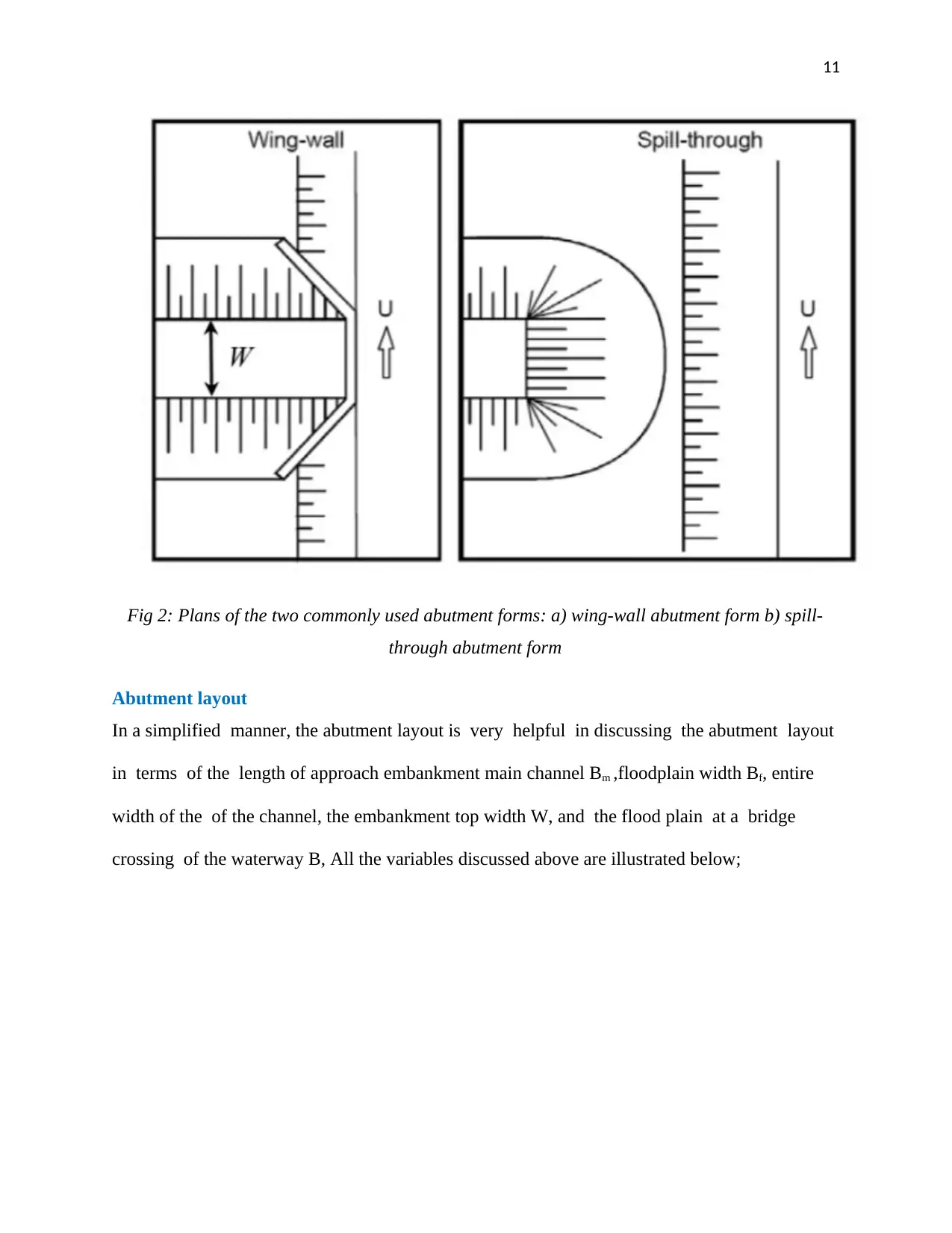
The spill-through abutment is characterized by the sloped sides, while abutment is
characterized by a vertical face together with wing wall which is used to retain an earth fill
approach embankment. The wing wall has the ability to be oriented in many different angles
and positions to the central panel of the abutment, even if a 45o angle is a representative
(Shahawy, 2018). A wing wall abutment having wing-angles at 90o to its central panel is
sometimes referred to as a vertical-wall abutment, and it is commonly used in the
construction of small abutments. The sheet-pile caissons which extend into the channel are
also viewed as a type of the vertical-wall abutment. Different other names for two forms that
will be used exists.
approach embankment (Nowak, 2018). The above characteristics, together with the waterways
channel morphology, soils, and boundary sediments, together with flow-resistance features,
influences the flow fields around the abutment, and hence, scour. A complicating and somewhat
a striking, characteristic of the bridge abutments is that few abutment situations
Abutment form
There are two forms of abutments that can be used in the construction and they are:
a) Spill-through abutments
b) Wing-wall abutments, this includes the vertical-wall abutment
The spill-through abutment is characterized by the sloped sides, while abutment is
characterized by a vertical face together with wing wall which is used to retain an earth fill
approach embankment. The wing wall has the ability to be oriented in many different angles
and positions to the central panel of the abutment, even if a 45o angle is a representative
(Shahawy, 2018). A wing wall abutment having wing-angles at 90o to its central panel is
sometimes referred to as a vertical-wall abutment, and it is commonly used in the
construction of small abutments. The sheet-pile caissons which extend into the channel are
also viewed as a type of the vertical-wall abutment. Different other names for two forms that
will be used exists.
Paraphrase This Document
Need a fresh take? Get an instant paraphrase of this document with our AI Paraphraser
11
Fig 2: Plans of the two commonly used abutment forms: a) wing-wall abutment form b) spill-
through abutment form
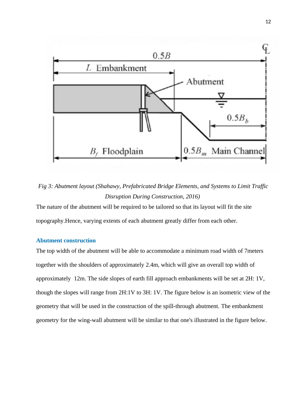
Abutment layout
In a simplified manner, the abutment layout is very helpful in discussing the abutment layout
in terms of the length of approach embankment main channel Bm ,floodplain width Bf, entire
width of the of the channel, the embankment top width W, and the flood plain at a bridge
crossing of the waterway B, All the variables discussed above are illustrated below;
Fig 2: Plans of the two commonly used abutment forms: a) wing-wall abutment form b) spill-
through abutment form
Abutment layout
In a simplified manner, the abutment layout is very helpful in discussing the abutment layout
in terms of the length of approach embankment main channel Bm ,floodplain width Bf, entire
width of the of the channel, the embankment top width W, and the flood plain at a bridge
crossing of the waterway B, All the variables discussed above are illustrated below;
12
Fig 3: Abutment layout (Shahawy, Prefabricated Bridge Elements, and Systems to Limit Traffic
Disruption During Construction, 2016)
The nature of the abutment will be required to be tailored so that its layout will fit the site
topography.Hence, varying extents of each abutment greatly differ from each other.
Abutment construction
The top width of the abutment will be able to accommodate a minimum road width of 7meters
together with the shoulders of approximately 2.4m, which will give an overall top width of
approximately 12m. The side slopes of earth fill approach embankments will be set at 2H: 1V,
though the slopes will range from 2H:1V to 3H: 1V. The figure below is an isometric view of the
geometry that will be used in the construction of the spill-through abutment. The embankment
geometry for the wing-wall abutment will be similar to that one's illustrated in the figure below.
⊘ This is a preview!⊘
Do you want full access?
Subscribe today to unlock all pages.
Trusted by 1+ million students worldwide
1 out of 50

Your All-in-One AI-Powered Toolkit for Academic Success.
+13062052269
info@desklib.com
Available 24*7 on WhatsApp / Email
![[object Object]](/_next/static/media/star-bottom.7253800d.svg)
Unlock your academic potential
Copyright © 2020–2026 A2Z Services. All Rights Reserved. Developed and managed by ZUCOL.