48360 Geotechnical Engineering: Construction Methods & Analysis
VerifiedAdded on 2023/06/03
|26
|5013
|477
Report
AI Summary
This geotechnical engineering report assesses the suitability of a site in Melbourne for constructing a concrete industrial building and a steel water tank. The report details the Standard Penetration Test (SPT) results, ground layer cross-section using Geostudio software, and appropriate construction methods, including the use of lattice beams, ground anchors, and the top-down method. It includes a preliminary design of retaining walls, analysis of mat foundation stability, maximum settlement calculations using Young's Modulus, and design considerations for the water tank foundation. The report concludes with recommendations for future soil explorations to inform future designs, emphasizing the importance of geotechnical knowledge in ensuring structural integrity and safety.
Construction Methods 1
CONSTRUCTION METHODS
By (Name)
Course
Professor’s name
University name
City, State
Date of submission
CONSTRUCTION METHODS
By (Name)
Course
Professor’s name
University name
City, State
Date of submission
Paraphrase This Document
Need a fresh take? Get an instant paraphrase of this document with our AI Paraphraser
Construction Methods 2
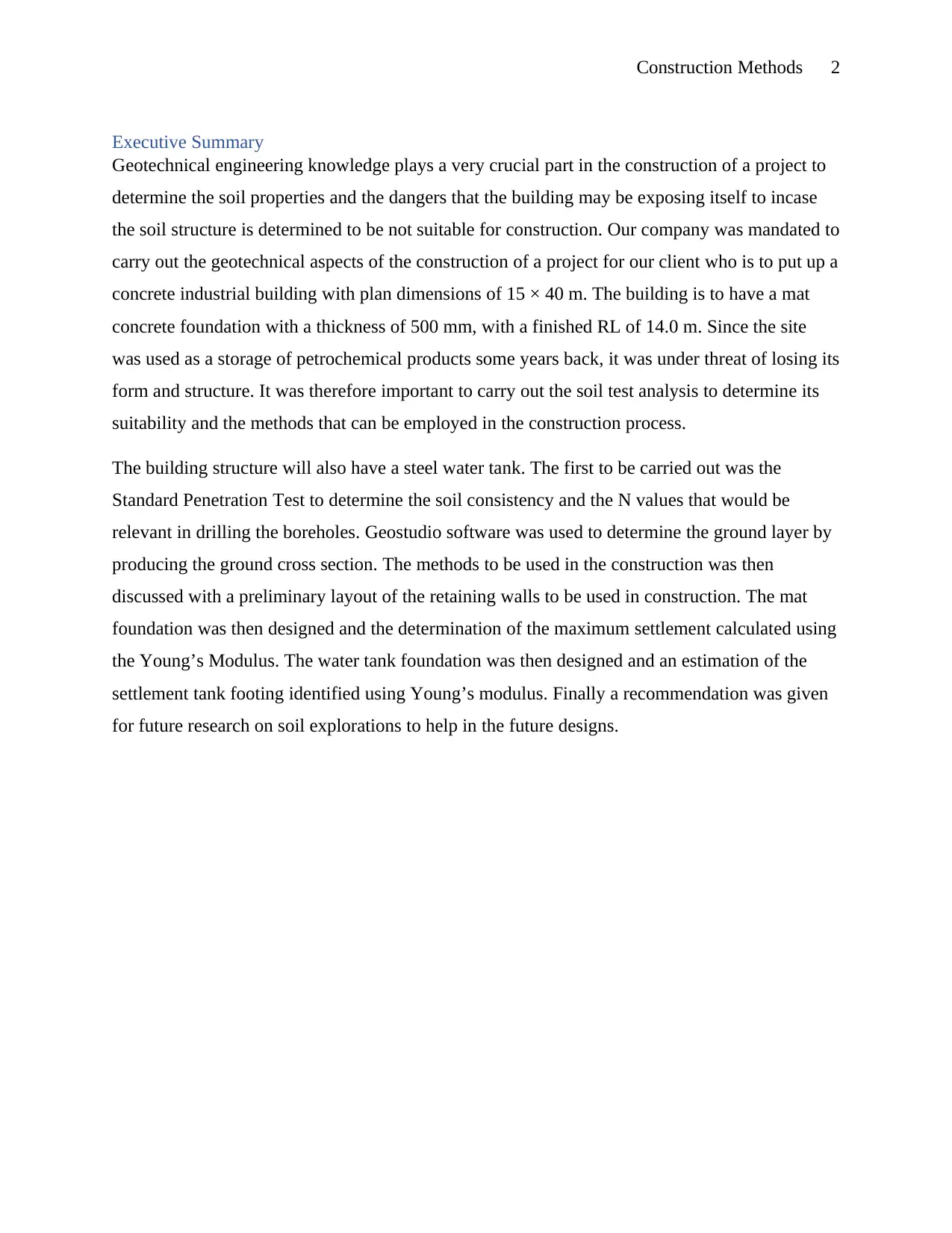
Executive Summary
Geotechnical engineering knowledge plays a very crucial part in the construction of a project to
determine the soil properties and the dangers that the building may be exposing itself to incase
the soil structure is determined to be not suitable for construction. Our company was mandated to
carry out the geotechnical aspects of the construction of a project for our client who is to put up a
concrete industrial building with plan dimensions of 15 × 40 m. The building is to have a mat
concrete foundation with a thickness of 500 mm, with a finished RL of 14.0 m. Since the site
was used as a storage of petrochemical products some years back, it was under threat of losing its
form and structure. It was therefore important to carry out the soil test analysis to determine its
suitability and the methods that can be employed in the construction process.
The building structure will also have a steel water tank. The first to be carried out was the
Standard Penetration Test to determine the soil consistency and the N values that would be
relevant in drilling the boreholes. Geostudio software was used to determine the ground layer by
producing the ground cross section. The methods to be used in the construction was then
discussed with a preliminary layout of the retaining walls to be used in construction. The mat
foundation was then designed and the determination of the maximum settlement calculated using
the Young’s Modulus. The water tank foundation was then designed and an estimation of the
settlement tank footing identified using Young’s modulus. Finally a recommendation was given
for future research on soil explorations to help in the future designs.
Construction Methods 3
Table of Content
Executive Summary.......................................................................................................................2
Introduction....................................................................................................................................3
Scope of work...............................................................................................................................4
Consistency of the soil layers based on SPT N-values................................................................5
Cross section of the ground layers of the site..............................................................................7
The construction methods that should be adopted in the construction....................................8
Use of lattice beams.....................................................................................................................8
Using Anchors in the ground.......................................................................................................9
The top-down method.................................................................................................................10
A general layout of the retaining walls around the proposed building..................................12
Retaining walls...........................................................................................................................12
Gravity retaining wall............................................................................................................13
Pile retaining wall..................................................................................................................14
Cantilever retaining walls......................................................................................................14
Anchored retaining walls.......................................................................................................15
Condition of stability of Retaining walls...................................................................................15
Loads on Retaining Walls..........................................................................................................16
Preliminary design of a retaining wall.......................................................................................17
The retaining structure employed between proposed building and water tank.........................17
The retaining structure employed between proposed and existing building plus proposed
building and planned car park...................................................................................................18
The retaining structure employed between proposed building and car park............................18
Factor of safety of the large mat foundation proposed for the building.................................18
Maximum Settlement of the footing...........................................................................................20
Circular tank footing...................................................................................................................20
Settlement of the footing.............................................................................................................22
Recommendations........................................................................................................................23
References.....................................................................................................................................24
⊘ This is a preview!⊘
Do you want full access?
Subscribe today to unlock all pages.
Trusted by 1+ million students worldwide
Construction Methods 4
Introduction
In most cases, a typical Geotechnical engineering projects starts with the definition of the
material properties, followed by a site investigation of the soil, fault distribution, rock, and
bedrock properties on and beneath the site area to determine the engineering properties which
include how the soil will interact with the proposed construction (Allen & Iano, 2017). Site
investigation help the project engineers to understand the site, These include the assessment of
risk to property, human, and the environment from the natural hazards which include landslides,
earthquakes, soil liquefaction, sinkholes, rock falls and debris flows (Allen & Iano, 2017).
Geotechnical engineers role is to design the earthworks, type of foundation and pavement
subgrades required to build the structure (Bahrami, et al., 2012). Foundation designs depend on
the type of the structure such as the high rise buildings, commercial structures, small structures
and bridges (Rose, et al., 2012). There are different types of foundations that are built above the
structure such as retaining walls, shallow and deep foundations (Bahrami, et al., 2012).
Earthworks include tunnels, reservoirs, embankments, channels, dikes and levees sanitary
landfills and hazardous wastes.
Cargo transporting company in Melbourne has approached Maestro Company which is our
geotechnical company to carry out an assessment on their site in Melbourne on geotechnical
aspects to determine the effectiveness of the soil for construction since the site was used before
as a storage area of petrochemical company, which means there has been oil spillage that have
happened on site for a long period of time which might contaminate the soil structure and
condition.
Scope of work
The building project will consist of
A concrete industrial building with plan dimensions of 15 m × 40 m. The building is to
have a mat concrete foundation with a thickness of 500 mm, with a finished RL of 14.0
m. The walls are load bearing and there are some internal columns carrying the weight of
the roof and other elements.
Paraphrase This Document
Need a fresh take? Get an instant paraphrase of this document with our AI Paraphraser
Construction Methods 5
A steel water tank having an external diameter of 13 m and an effective height of 8 m,
with its base at RL 17 m (top of the footing).
There is an existing one-storey double brick building on the site. The RL of the slab on
the ground is 17.5 m (top of the slab on ground).
A Site Plan is attached below, showing the location of the tank, the car park (RL 17.5 m, finished
surfacing) the proposed and existing buildings. The Structural Engineer for the project has
determined the proposed building loads and they are as follows:
Total vertical loads: 250 MN per meter run (NOTE: the weight of foundation is
included.)
Total moment in each direction: 500 MN.m
Total horizontal loads: 50 MN.
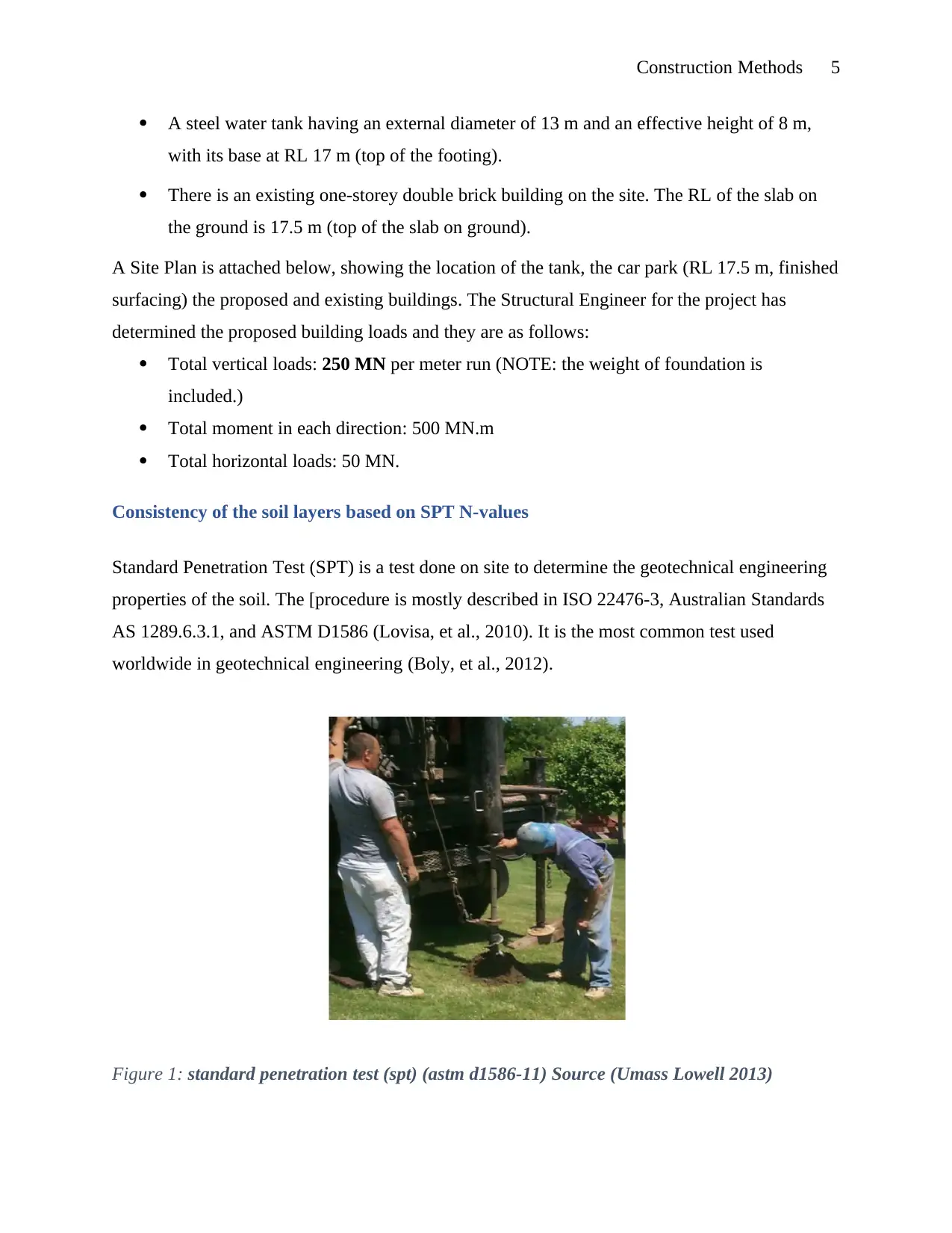
Consistency of the soil layers based on SPT N-values
Standard Penetration Test (SPT) is a test done on site to determine the geotechnical engineering
properties of the soil. The [procedure is mostly described in ISO 22476-3, Australian Standards
AS 1289.6.3.1, and ASTM D1586 (Lovisa, et al., 2010). It is the most common test used
worldwide in geotechnical engineering (Boly, et al., 2012).
Figure 1: standard penetration test (spt) (astm d1586-11) Source (Umass Lowell 2013)
A steel water tank having an external diameter of 13 m and an effective height of 8 m,
with its base at RL 17 m (top of the footing).
There is an existing one-storey double brick building on the site. The RL of the slab on
the ground is 17.5 m (top of the slab on ground).
A Site Plan is attached below, showing the location of the tank, the car park (RL 17.5 m, finished
surfacing) the proposed and existing buildings. The Structural Engineer for the project has
determined the proposed building loads and they are as follows:
Total vertical loads: 250 MN per meter run (NOTE: the weight of foundation is
included.)
Total moment in each direction: 500 MN.m
Total horizontal loads: 50 MN.
Consistency of the soil layers based on SPT N-values
Standard Penetration Test (SPT) is a test done on site to determine the geotechnical engineering
properties of the soil. The [procedure is mostly described in ISO 22476-3, Australian Standards
AS 1289.6.3.1, and ASTM D1586 (Lovisa, et al., 2010). It is the most common test used
worldwide in geotechnical engineering (Boly, et al., 2012).
Figure 1: standard penetration test (spt) (astm d1586-11) Source (Umass Lowell 2013)
Construction Methods 6
Soil consistency is the ability of the soil materials to hold itself by resisting any form of pressure
that may lead to the deformation or rupture of the soil (Chotia, et al., 2012). It is measured for
dry soil and wet moist samples. When it comes to the wet soil sample, it is expressed as both
plasticity and thickness (Long & Vietnam, 2010).
The boreholes are usually drilled deeper and the test repeated again. During this process, errors
might occur per interval due to the poor state of soil recovery (Clayton, et al., 2012). The number
of the hammer strikes it takes for a tube to dig deep or penetrate the 2nd and 3rd 6 inch depth is
referred to as “standard penetration resistance” or referred to as ‘N-value (Clayton, et al., 2012).
For 3 or 4 increments of six inches each
Three increments: we get the sum of the last 2 increments in SPT N value. For 4 increments, the
same procedure is repeated (Chotia, et al., 2012).
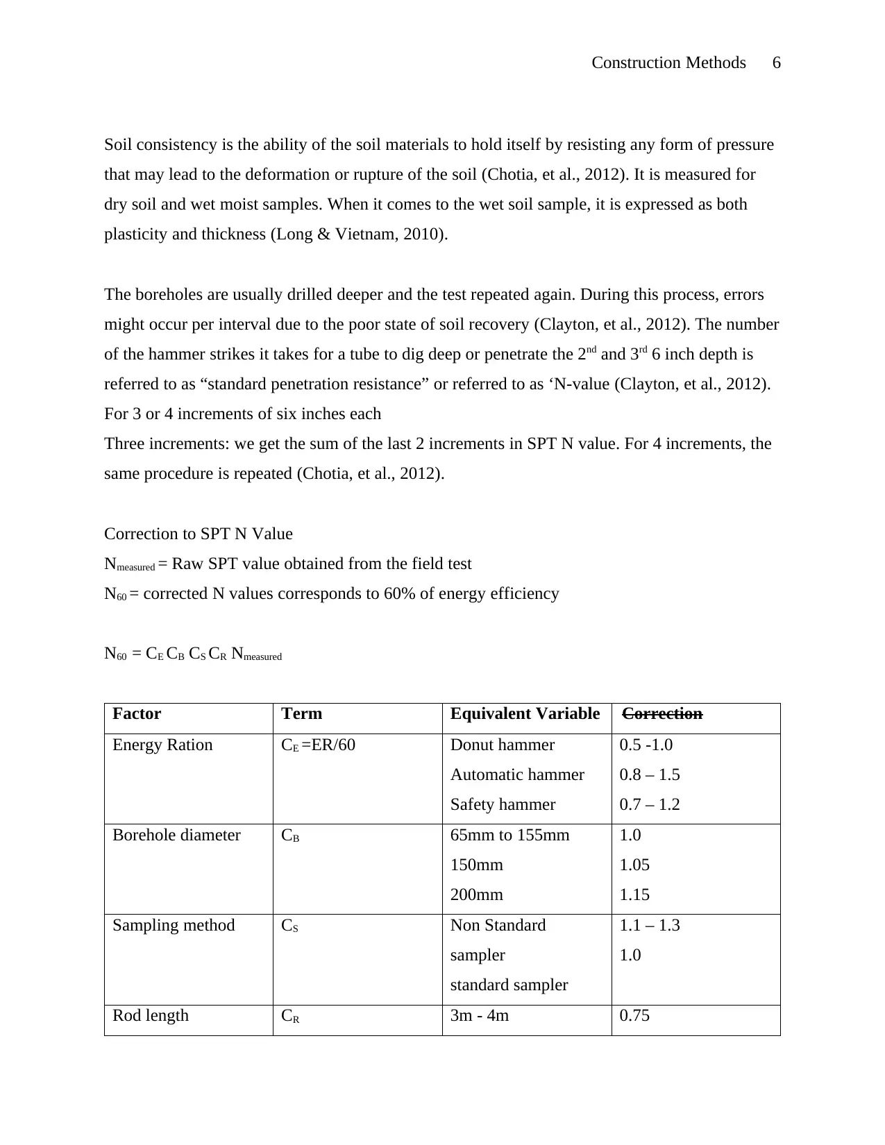
Correction to SPT N Value
Nmeasured = Raw SPT value obtained from the field test
N60 = corrected N values corresponds to 60% of energy efficiency
N60 = CE CB CS CR Nmeasured
Factor Term Equivalent Variable Correction
Energy Ration CE =ER/60 Donut hammer
Automatic hammer
Safety hammer
0.5 -1.0
0.8 – 1.5
0.7 – 1.2
Borehole diameter CB 65mm to 155mm
150mm
200mm
1.0
1.05
1.15
Sampling method CS Non Standard
sampler
standard sampler
1.1 – 1.3
1.0
Rod length CR 3m - 4m 0.75
Soil consistency is the ability of the soil materials to hold itself by resisting any form of pressure
that may lead to the deformation or rupture of the soil (Chotia, et al., 2012). It is measured for
dry soil and wet moist samples. When it comes to the wet soil sample, it is expressed as both
plasticity and thickness (Long & Vietnam, 2010).
The boreholes are usually drilled deeper and the test repeated again. During this process, errors
might occur per interval due to the poor state of soil recovery (Clayton, et al., 2012). The number
of the hammer strikes it takes for a tube to dig deep or penetrate the 2nd and 3rd 6 inch depth is
referred to as “standard penetration resistance” or referred to as ‘N-value (Clayton, et al., 2012).
For 3 or 4 increments of six inches each
Three increments: we get the sum of the last 2 increments in SPT N value. For 4 increments, the
same procedure is repeated (Chotia, et al., 2012).
Correction to SPT N Value
Nmeasured = Raw SPT value obtained from the field test
N60 = corrected N values corresponds to 60% of energy efficiency
N60 = CE CB CS CR Nmeasured
Factor Term Equivalent Variable Correction
Energy Ration CE =ER/60 Donut hammer
Automatic hammer
Safety hammer
0.5 -1.0
0.8 – 1.5
0.7 – 1.2
Borehole diameter CB 65mm to 155mm
150mm
200mm
1.0
1.05
1.15
Sampling method CS Non Standard
sampler
standard sampler
1.1 – 1.3
1.0
Rod length CR 3m - 4m 0.75
⊘ This is a preview!⊘
Do you want full access?
Subscribe today to unlock all pages.
Trusted by 1+ million students worldwide
Construction Methods 7
4m - 6m
6m – 10m
>10m
0.85
0.95
1.00
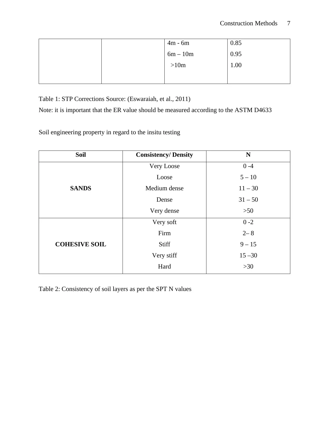
Table 1: STP Corrections Source: (Eswaraiah, et al., 2011)
Note: it is important that the ER value should be measured according to the ASTM D4633
Soil engineering property in regard to the insitu testing
Soil Consistency/ Density N
SANDS
Very Loose
Loose
Medium dense
Dense
Very dense
0 -4
5 – 10
11 – 30
31 – 50
>50
COHESIVE SOIL
Very soft
Firm
Stiff
Very stiff
Hard
0 -2
2– 8
9 – 15
15 –30
>30
Table 2: Consistency of soil layers as per the SPT N values
4m - 6m
6m – 10m
>10m
0.85
0.95
1.00
Table 1: STP Corrections Source: (Eswaraiah, et al., 2011)
Note: it is important that the ER value should be measured according to the ASTM D4633
Soil engineering property in regard to the insitu testing
Soil Consistency/ Density N
SANDS
Very Loose
Loose
Medium dense
Dense
Very dense
0 -4
5 – 10
11 – 30
31 – 50
>50
COHESIVE SOIL
Very soft
Firm
Stiff
Very stiff
Hard
0 -2
2– 8
9 – 15
15 –30
>30
Table 2: Consistency of soil layers as per the SPT N values
Paraphrase This Document
Need a fresh take? Get an instant paraphrase of this document with our AI Paraphraser
Construction Methods 8
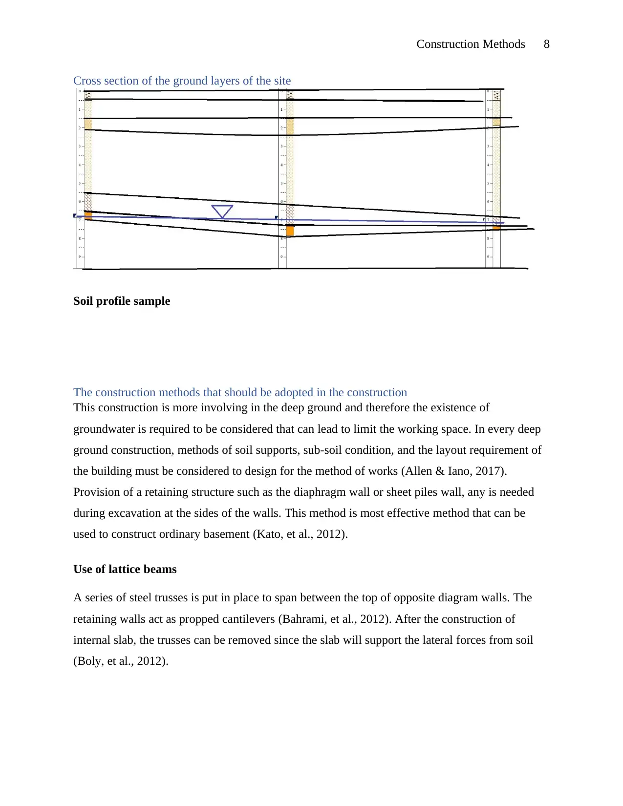
Cross section of the ground layers of the site
Soil profile sample
The construction methods that should be adopted in the construction
This construction is more involving in the deep ground and therefore the existence of
groundwater is required to be considered that can lead to limit the working space. In every deep
ground construction, methods of soil supports, sub-soil condition, and the layout requirement of
the building must be considered to design for the method of works (Allen & Iano, 2017).
Provision of a retaining structure such as the diaphragm wall or sheet piles wall, any is needed
during excavation at the sides of the walls. This method is most effective method that can be
used to construct ordinary basement (Kato, et al., 2012).
Use of lattice beams
A series of steel trusses is put in place to span between the top of opposite diagram walls. The
retaining walls act as propped cantilevers (Bahrami, et al., 2012). After the construction of
internal slab, the trusses can be removed since the slab will support the lateral forces from soil
(Boly, et al., 2012).
Construction Methods 9
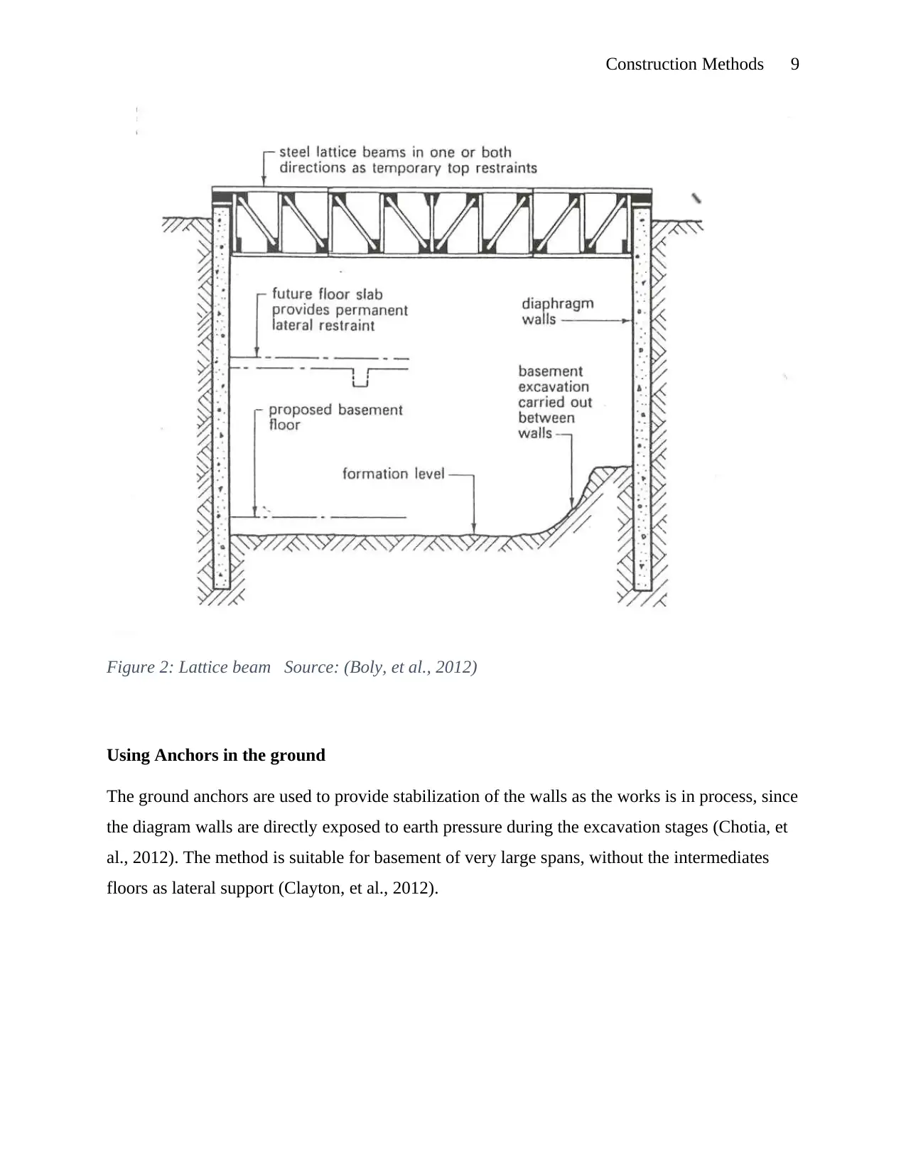
Figure 2: Lattice beam Source: (Boly, et al., 2012)
Using Anchors in the ground
The ground anchors are used to provide stabilization of the walls as the works is in process, since
the diagram walls are directly exposed to earth pressure during the excavation stages (Chotia, et
al., 2012). The method is suitable for basement of very large spans, without the intermediates
floors as lateral support (Clayton, et al., 2012).
⊘ This is a preview!⊘
Do you want full access?
Subscribe today to unlock all pages.
Trusted by 1+ million students worldwide
Construction Methods 10
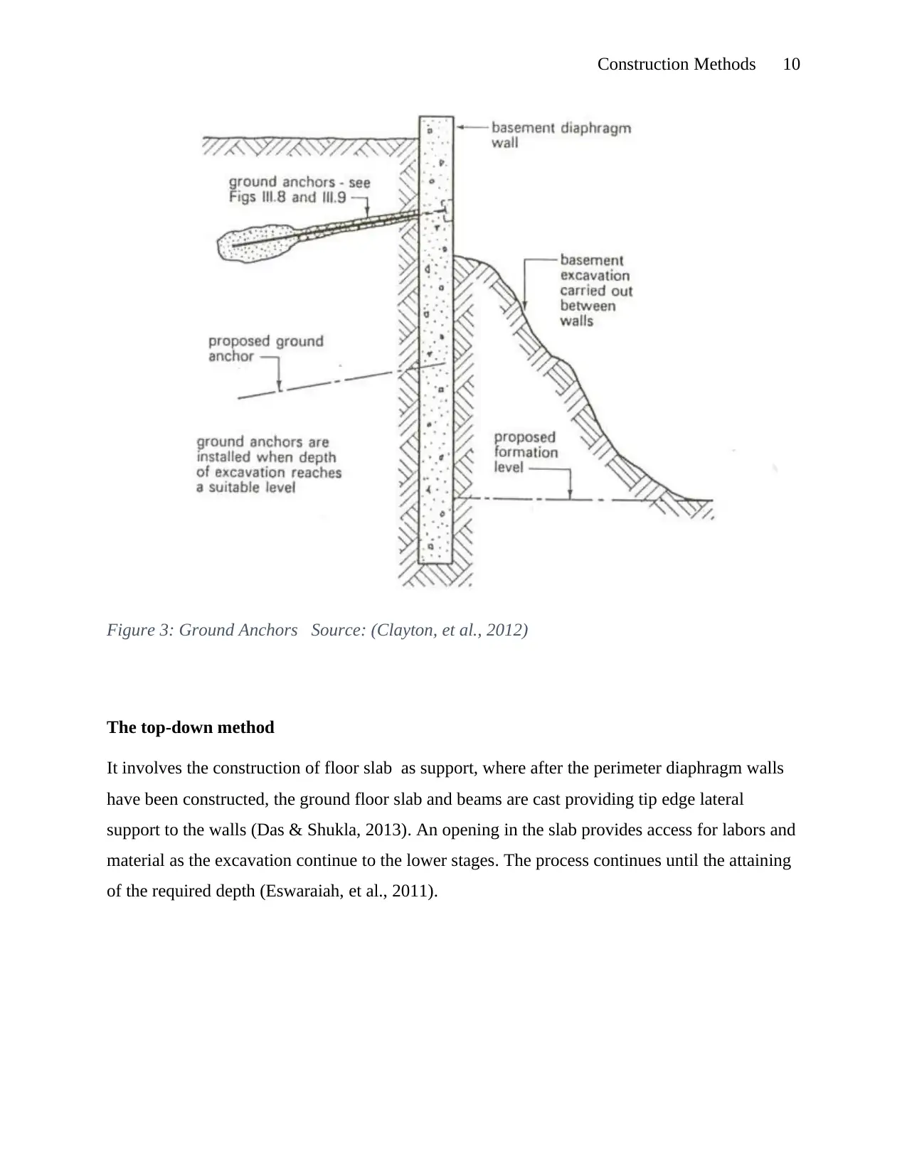
Figure 3: Ground Anchors Source: (Clayton, et al., 2012)
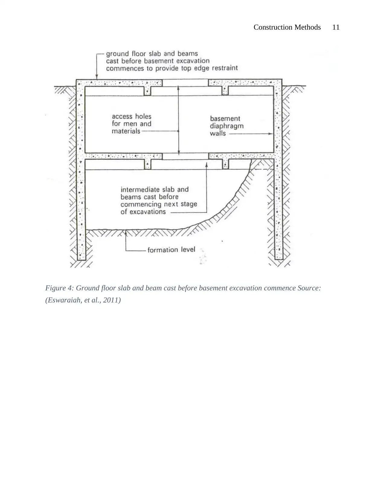
The top-down method
It involves the construction of floor slab as support, where after the perimeter diaphragm walls
have been constructed, the ground floor slab and beams are cast providing tip edge lateral
support to the walls (Das & Shukla, 2013). An opening in the slab provides access for labors and
material as the excavation continue to the lower stages. The process continues until the attaining
of the required depth (Eswaraiah, et al., 2011).
Figure 3: Ground Anchors Source: (Clayton, et al., 2012)
The top-down method
It involves the construction of floor slab as support, where after the perimeter diaphragm walls
have been constructed, the ground floor slab and beams are cast providing tip edge lateral
support to the walls (Das & Shukla, 2013). An opening in the slab provides access for labors and
material as the excavation continue to the lower stages. The process continues until the attaining
of the required depth (Eswaraiah, et al., 2011).
Paraphrase This Document
Need a fresh take? Get an instant paraphrase of this document with our AI Paraphraser
Construction Methods 11
Figure 4: Ground floor slab and beam cast before basement excavation commence Source:
(Eswaraiah, et al., 2011)
Figure 4: Ground floor slab and beam cast before basement excavation commence Source:
(Eswaraiah, et al., 2011)
Construction Methods 12
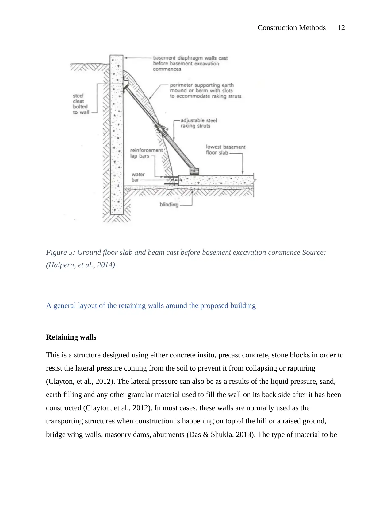
Figure 5: Ground floor slab and beam cast before basement excavation commence Source:
(Halpern, et al., 2014)
A general layout of the retaining walls around the proposed building
Retaining walls
This is a structure designed using either concrete insitu, precast concrete, stone blocks in order to
resist the lateral pressure coming from the soil to prevent it from collapsing or rapturing
(Clayton, et al., 2012). The lateral pressure can also be as a results of the liquid pressure, sand,
earth filling and any other granular material used to fill the wall on its back side after it has been
constructed (Clayton, et al., 2012). In most cases, these walls are normally used as the
transporting structures when construction is happening on top of the hill or a raised ground,
bridge wing walls, masonry dams, abutments (Das & Shukla, 2013). The type of material to be
⊘ This is a preview!⊘
Do you want full access?
Subscribe today to unlock all pages.
Trusted by 1+ million students worldwide
1 out of 26
Related Documents


Your All-in-One AI-Powered Toolkit for Academic Success.
+13062052269
info@desklib.com
Available 24*7 on WhatsApp / Email
![[object Object]](/_next/static/media/star-bottom.7253800d.svg)
Unlock your academic potential
Copyright © 2020–2026 A2Z Services. All Rights Reserved. Developed and managed by ZUCOL.