Assessment: Structural Principles in Residential Low-Rise Construction
VerifiedAdded on 2022/12/18
|21
|3688
|412
Report
AI Summary
This report delves into the application of structural principles in low-rise residential constructions, focusing on stiffened raft slabs and suspended floors. It meticulously details the steel reinforcement used (mesh and bars), plastic products, concrete types (strength grade, aggregate size, slump, and curing process), and formwork. The report examines the basic features of each concrete slab type, including insitu, composite steel/concrete, and precast concrete. It also provides detailed information on steel reinforcement, lapping requirements, and methods for concrete pouring, including precautions observed during the process. The report further explores concrete composition, including water-cement ratios, and discusses excavation and formwork construction. It emphasizes the importance of concrete curing, concluding with a summary of the key findings and references to relevant standards like AS2870, providing a comprehensive overview of residential construction techniques.
1
APPLY STRUCTURAL PRINCIPLES TO RESIDENTIAL LOW-RISE
CONSTRUCTIONS
By Name
Course
Instructor
Institution
Location
Date
APPLY STRUCTURAL PRINCIPLES TO RESIDENTIAL LOW-RISE
CONSTRUCTIONS
By Name
Course
Instructor
Institution
Location
Date
Paraphrase This Document
Need a fresh take? Get an instant paraphrase of this document with our AI Paraphraser
2
STIFFENED RAFT GROUND SLABS AND SUSPENDED SLABS
Task instructions:
Use technical report template provided in with all technical data researched from AS2870 to be
referenced into completed Bibliography.
Each step needs an individual image/s with appropriate heading and relevant text.
You need to discuss things like the steel used as reinforcement (mesh, bars), the plastic products
required, the type of concrete used (strength grade, aggregate size, slump, curing process), formwork
etc…
This assessment task covers 15% of your overall marks for this unit.
No sharing of images or internet downloads accepted
This Assessment Task is to be presented in a professional report format as set out in the report
template provided.
In a Word doc format (not in Pages Format) of the Assessment Task, dated with the unit code and title
and Assessment Task number.
3
TABLE OF CONTENTS
Introduction................................................................................................................................4
Stiffened raft slab.......................................................................................................................5
Suspended floors........................................................................................................................6
Basic features of each concrete slab...........................................................................................6
The steel used as reinforcement (mesh, bars)............................................................................8
Laps in reinforcements...............................................................................................................8
Methods of concrete pouring...................................................................................................10
Precautions observed during concrete pouring.......................................................................10
CONCRETE USED.................................................................................................................11
Water-cement ratio...................................................................................................................12
EXCAVATION........................................................................................................................12
FORMWORK FOR GROUND AND SUSPENDED FLOORS.............................................14
Martials used in the construction of the formwork..................................................................15
CONCRETE CURING............................................................................................................17
Importance of concrete curing.................................................................................................17
CONCLUSION........................................................................................................................18
REFERENCES.........................................................................................................................20
⊘ This is a preview!⊘
Do you want full access?
Subscribe today to unlock all pages.
Trusted by 1+ million students worldwide
4
Introduction
The main function of the footing to distribute the vertical loads from the building to the
foundation and also to ensure that the building superstructure performs satisfactorily,
especially when it is on a foundation which is subjected to movement due to moisture
changes (National Research Council. Committee on Residential Slabs-on-Ground, 2017, p.
473).
The most common movement arises due to the changes in the reactive soils. The moment
soil becomes wet, it swells and increase in volume, and the same timey shrink as they dry out.
This is the reason why cracks appear in clay soil during the prolonged droughts. The
deeper or the more reactive the soil is affected the large the surface of movement will be.
The construction of a concrete slab on the ground during the construction process it is like
covering the ground with an impermeable membrane. The slab prevents any moisture rising
beneath the slab from evaporating soil below the slab will therefore remain damp and at the
same time the moisture content may even increase and this will result in a directs increase in
the rate of reaction hence making the soil beneath the slab to swell (Laws, 2011, p. 168).
Swelling soils are among the main geological hazards which causes a lot of damages to
buildings in different parts of the world. The main aim of this study is to investigate
broadly and in-depth the stiffened raft slab as one of the different foundations that are
available in the construction of a simple building on the Australian Expansive soils, and
at the same time to make better the utilization of its benefits ; economical to construct
and its ability to withstand rigidity against the anticipated large soils differential heave
as the floating foundation. In most cases concrete offers the flexibility of a structural
material which can be cast into almost any desired shape and size. The application of
concrete in the construction n can be able to respond to the many specific requirements and
Paraphrase This Document
Need a fresh take? Get an instant paraphrase of this document with our AI Paraphraser
5
the different design consideration found in most modern residential buildings (Sipek, et al.,
2013, p. 552).
Stiffened raft slab
The stiffened raft slab is made up a concrete slab on the ground which is stiffened by the
integral edge beams and a grid of the internal beams, this type of a raft slab is also referred
to as a slab-on-ground footing. The floor slab in most cases is placed at the same time as the
internal and external beams which in most cases are reinforced. The internal beams are not
needed on sites which are considered to be stable while for the more-reactive sites the
beam quality and size of the reinforcement are increased in order to suit the site conditions.
The stiffened raft slabs in most cases require only concrete pour, which makes them to be
economical in labour and material use (Bolza, 2011, p. 296). On the uncontrolled fill sites
this can be adapted to be supported on the mass concrete piles/piles which are founded on
natural materials.
6
Suspended floors
The three common suspended concrete floors which are suitable for the construction of
residential buildings are; composite steel/concrete, insitu concrete and precast concrete.
For many years the insitu concrete slabs have been used in the construction of the residential
buildings through the incorporation of fabricated systems is significantly helps in reducing
the cost of convectional framework, construction time and on-site activities. The savings
essentially result from the following;
There is no convectional formwork which is required, with that there is minimal time
which is required for the placement and removal of any temporary propping.
There is an intermediate, safe working area slab level which is provided. Beneath the
slab is a secure, waterproof area which is achieved, which is suitable for the possible
early fit-out and the storage (Commonwealth Scientific and Industrial Research
Organization (Australia). Division of Building Research, 2012, p. 327).
All the floor elements are delivered to the site when they are required, hence
minimizing the site storage.
Basic features of each concrete slab
i) Insitu
This is the most flexible concrete slab in that the slab can be designed to carry the walls of
any type anywhere within their span, which is unrestricted by the position of the walls i.e.
the layout of the rooms below them. The insitu slabs are individually designed for specific
projects. In the insitu slabs support may take form of the beams or the walls, themselves
being supported by either the columns or the beams (Barnes, 2018, p. 784).
⊘ This is a preview!⊘
Do you want full access?
Subscribe today to unlock all pages.
Trusted by 1+ million students worldwide
7
ii) Composite steel/concrete
In this type of the concrete slab, proprietary steel decking acts as the non-recoverable
formwork and as the partial reinforcement for the floor slab. The decking spans in a single
way and generally will be continuous over several supports. The single spans are,
nevertheless common and acceptable. The support for this type of slabs is similar to the insitu
slabs.
iii) Precast concrete slab
This concrete slab makes application of precast planks or panels, which b spans in a single
direction. In most cases a concrete topping is needed, in some cases for structural purposes
and hence reinforced, sometimes only to offer a level surface for the application of the floor
finishes. Just as for the insitu floor slabs the support for the pranks can take many different
forms (Great Britain. Property Services Agency, Great Britain. Department of the
Environment, Great Britain. Ministry of Public Building and Works, 2014, p. 328).
Paraphrase This Document
Need a fresh take? Get an instant paraphrase of this document with our AI Paraphraser
8
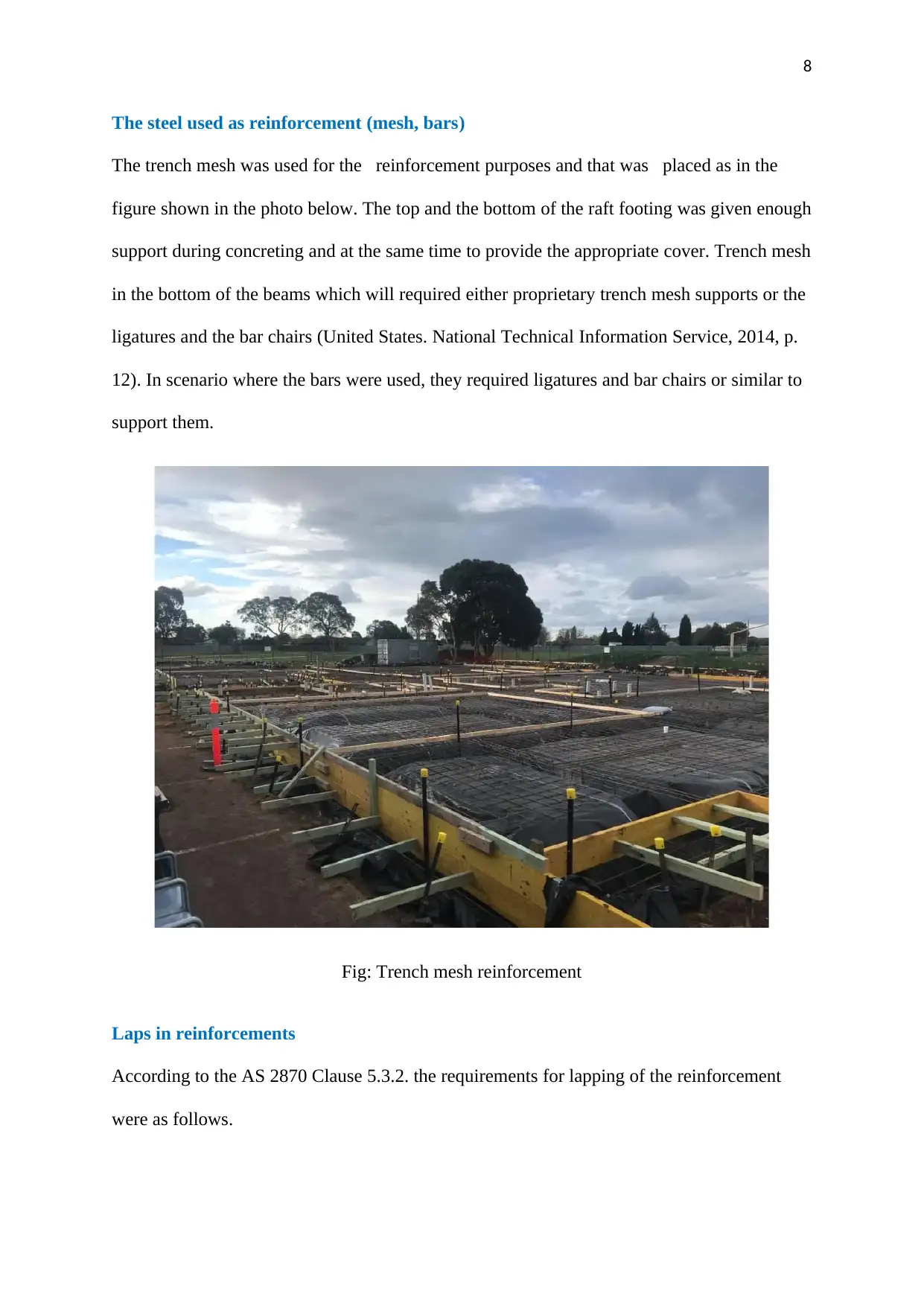
The steel used as reinforcement (mesh, bars)
The trench mesh was used for the reinforcement purposes and that was placed as in the
figure shown in the photo below. The top and the bottom of the raft footing was given enough
support during concreting and at the same time to provide the appropriate cover. Trench mesh
in the bottom of the beams which will required either proprietary trench mesh supports or the
ligatures and the bar chairs (United States. National Technical Information Service, 2014, p.
12). In scenario where the bars were used, they required ligatures and bar chairs or similar to
support them.
Fig: Trench mesh reinforcement
Laps in reinforcements
According to the AS 2870 Clause 5.3.2. the requirements for lapping of the reinforcement
were as follows.
9
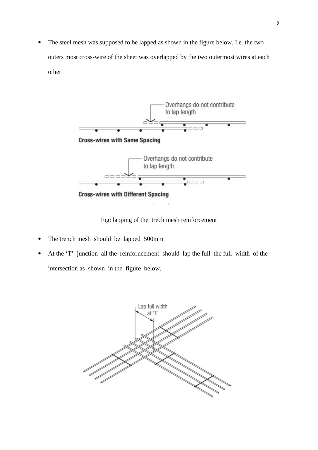
The steel mesh was supposed to be lapped as shown in the figure below. I.e. the two
outers most cross-wire of the sheet was overlapped by the two outermost wires at each
other
Fig: lapping of the trech mesh reinforcement
The trench mesh should be lapped 500mm
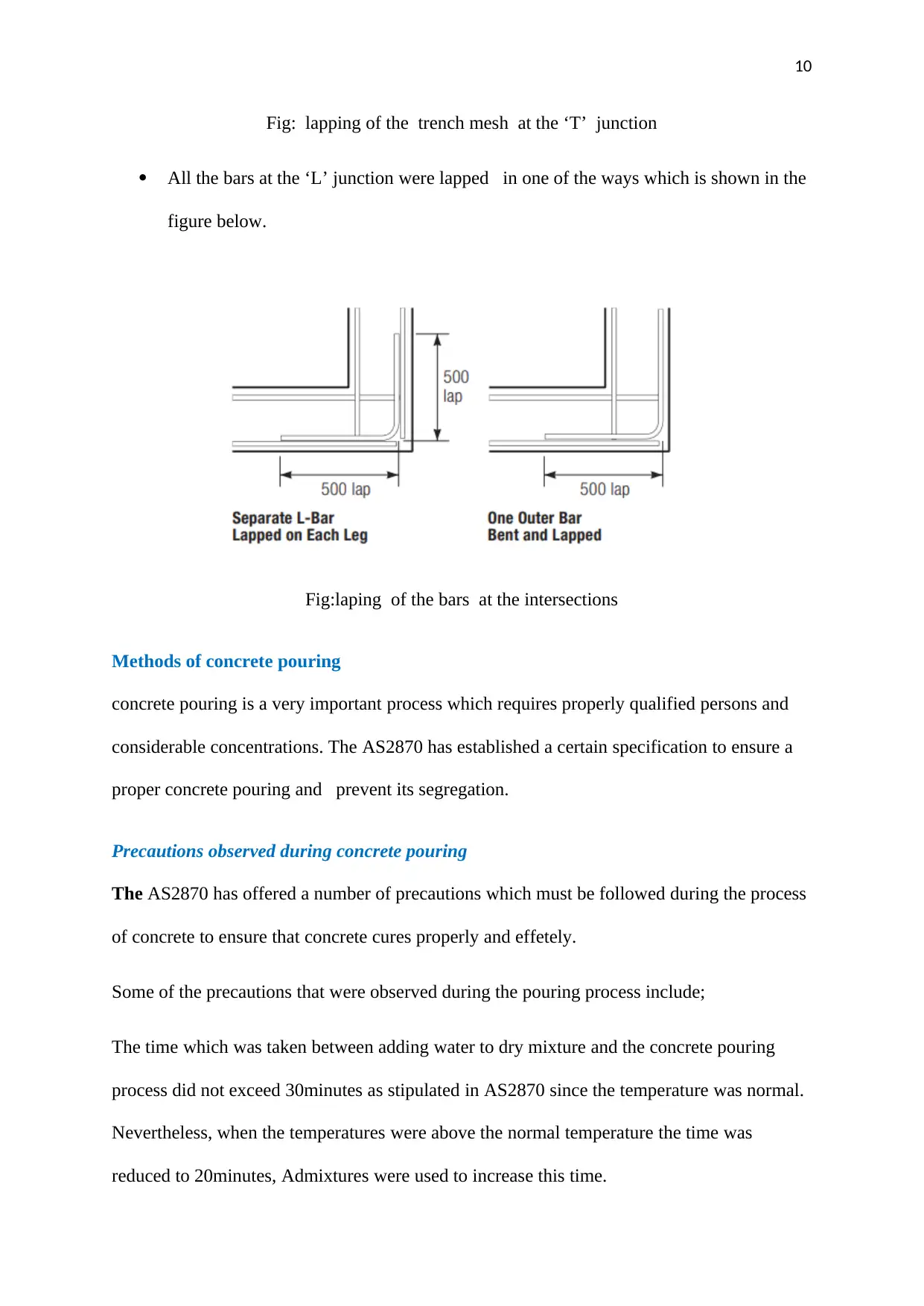
At the ‘T’ junction all the reinforncement should lap the full the full width of the
intersection as shown in the figure below.
The steel mesh was supposed to be lapped as shown in the figure below. I.e. the two
outers most cross-wire of the sheet was overlapped by the two outermost wires at each
other
Fig: lapping of the trech mesh reinforcement
The trench mesh should be lapped 500mm
At the ‘T’ junction all the reinforncement should lap the full the full width of the
intersection as shown in the figure below.
⊘ This is a preview!⊘
Do you want full access?
Subscribe today to unlock all pages.
Trusted by 1+ million students worldwide
10
Fig: lapping of the trench mesh at the ‘T’ junction
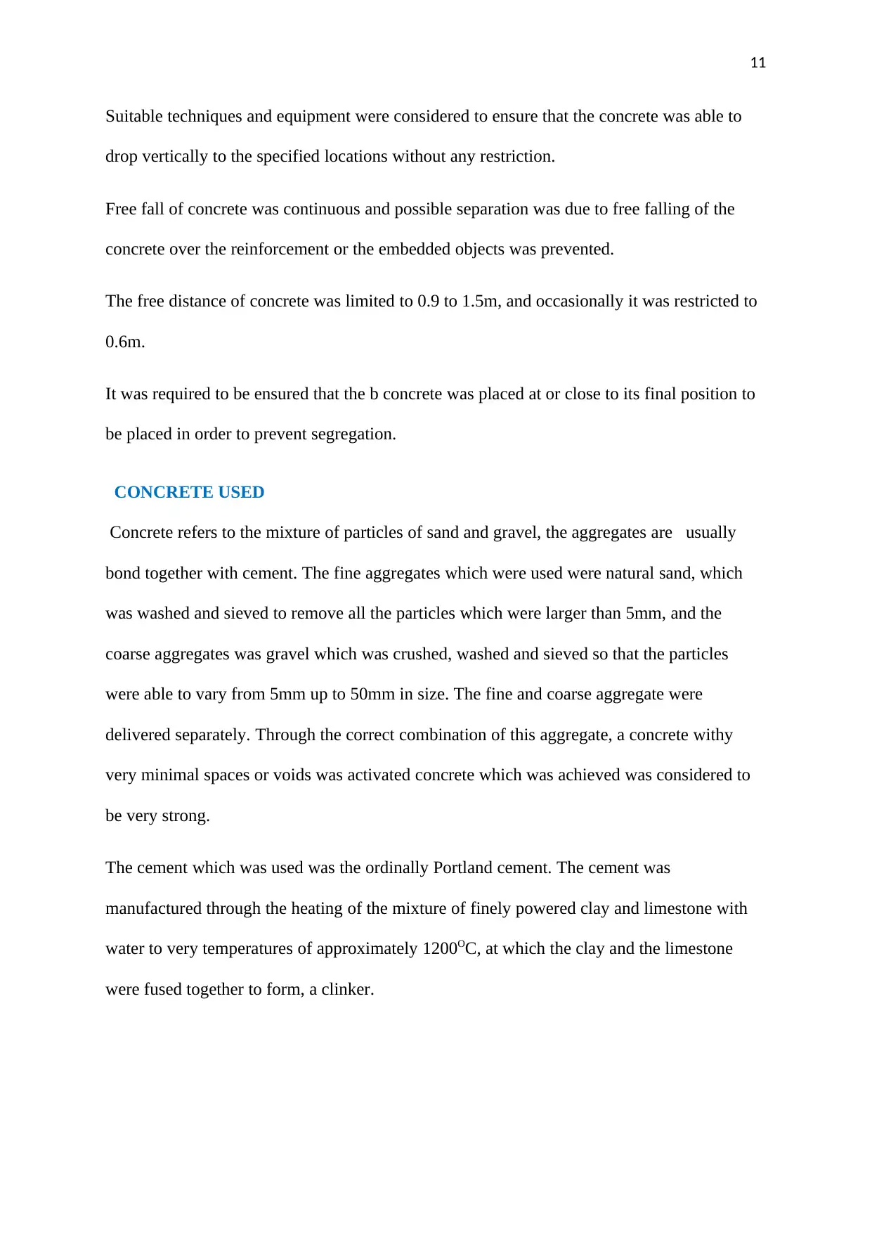
All the bars at the ‘L’ junction were lapped in one of the ways which is shown in the
figure below.
Fig:laping of the bars at the intersections
Methods of concrete pouring
concrete pouring is a very important process which requires properly qualified persons and
considerable concentrations. The AS2870 has established a certain specification to ensure a
proper concrete pouring and prevent its segregation.
Precautions observed during concrete pouring
The AS2870 has offered a number of precautions which must be followed during the process
of concrete to ensure that concrete cures properly and effetely.
Some of the precautions that were observed during the pouring process include;
The time which was taken between adding water to dry mixture and the concrete pouring
process did not exceed 30minutes as stipulated in AS2870 since the temperature was normal.
Nevertheless, when the temperatures were above the normal temperature the time was
reduced to 20minutes, Admixtures were used to increase this time.
Fig: lapping of the trench mesh at the ‘T’ junction
All the bars at the ‘L’ junction were lapped in one of the ways which is shown in the
figure below.
Fig:laping of the bars at the intersections
Methods of concrete pouring
concrete pouring is a very important process which requires properly qualified persons and
considerable concentrations. The AS2870 has established a certain specification to ensure a
proper concrete pouring and prevent its segregation.
Precautions observed during concrete pouring
The AS2870 has offered a number of precautions which must be followed during the process
of concrete to ensure that concrete cures properly and effetely.
Some of the precautions that were observed during the pouring process include;
The time which was taken between adding water to dry mixture and the concrete pouring
process did not exceed 30minutes as stipulated in AS2870 since the temperature was normal.
Nevertheless, when the temperatures were above the normal temperature the time was
reduced to 20minutes, Admixtures were used to increase this time.
Paraphrase This Document
Need a fresh take? Get an instant paraphrase of this document with our AI Paraphraser
11
Suitable techniques and equipment were considered to ensure that the concrete was able to
drop vertically to the specified locations without any restriction.
Free fall of concrete was continuous and possible separation was due to free falling of the
concrete over the reinforcement or the embedded objects was prevented.
The free distance of concrete was limited to 0.9 to 1.5m, and occasionally it was restricted to
0.6m.
It was required to be ensured that the b concrete was placed at or close to its final position to
be placed in order to prevent segregation.
CONCRETE USED
Concrete refers to the mixture of particles of sand and gravel, the aggregates are usually
bond together with cement. The fine aggregates which were used were natural sand, which
was washed and sieved to remove all the particles which were larger than 5mm, and the
coarse aggregates was gravel which was crushed, washed and sieved so that the particles
were able to vary from 5mm up to 50mm in size. The fine and coarse aggregate were
delivered separately. Through the correct combination of this aggregate, a concrete withy
very minimal spaces or voids was activated concrete which was achieved was considered to
be very strong.
The cement which was used was the ordinally Portland cement. The cement was
manufactured through the heating of the mixture of finely powered clay and limestone with
water to very temperatures of approximately 1200OC, at which the clay and the limestone
were fused together to form, a clinker.
12
Water-cement ratio
The materials which were used in making concrete were mixed with water for two main
reasons i.e. firstly, to facilitate the reaction between the cement and the water, which leads in
the cement acting as a binding agent and secondly to make the concrete plastic so that it can
be easily placed during the construction process. The ratio of cement to water which was used
has a great impact on the final strength of the concreate. In the scenario where too much
little water was used the concrete which was obtained was too stiff to an extent that it was not
possible to be compacted and in the scenarios where too much water was used the concrete
was not able to develop full strength. During the mixing of the concrete very little water
required to ensure that a full chemical reaction was to take place within the concrete mix.
Any excess water was not used since it was too leave very small voids the moment the excess
water was to evaporate.
EXCAVATION
Generally, excavation refers to the process of loosening and taking out materials leaving
space below or above the ground. In this project the ground was excavated to the required
levels. all the roots and grass were dug out until the firm soil was reached. The excavation
was carried out in way which was to ensure that the excavated whole was bigger than the
required size to ensure that tit catered for formwork. All the edges and shapes were kept in
square shape.
Since the residential building which was to be constructed can be classified as a small
project or a confined space, the process of excavation was carried out by the use of manual
means where simple tools were used during the excavation, some of the materials that were
used include; shovels, wheelbarrows and picks. But in the scenarios where the construction
projects required heavy plants were to be used in the excavation. Some o0f the materials that
⊘ This is a preview!⊘
Do you want full access?
Subscribe today to unlock all pages.
Trusted by 1+ million students worldwide
1 out of 21
Related Documents


Your All-in-One AI-Powered Toolkit for Academic Success.
+13062052269
info@desklib.com
Available 24*7 on WhatsApp / Email
![[object Object]](/_next/static/media/star-bottom.7253800d.svg)
Unlock your academic potential
Copyright © 2020–2026 A2Z Services. All Rights Reserved. Developed and managed by ZUCOL.