Detailed Report on Reinforced Concrete Frame Construction - CPCC5018
VerifiedAdded on  2023/04/08
|24
|3859
|77
Report
AI Summary
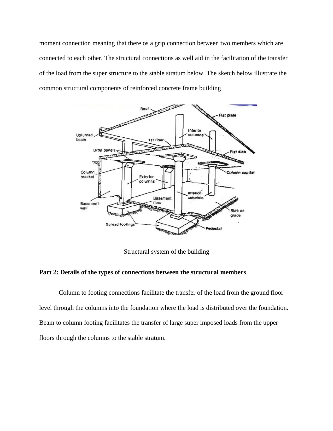
This report provides a detailed analysis of reinforced concrete frame construction, examining various technical aspects of a medium-rise building. The report begins with an introduction to reinforced concrete frame construction, outlining its components and purpose. It then delves into six key areas: footing systems, structural systems, floor systems, wall systems, services, and roofing systems. The footing system analysis includes a description of the footing type, a section through a typical footing system, and foundation footing drainage. The structural systems section covers how the frame supports building loads and details connections between structural members. The floor systems section describes the floor system used, its construction sequence, layers of reinforcement, and information on the tag. The wall systems section includes photographs of the wall system, determines if the walls add to the structural stability of the building. The report uses photographs and sketches to illustrate the various aspects of the discussion, offering a comprehensive overview of reinforced concrete frame construction. The report is based on an examination of an already constructed and completed medium rise, reinforced concrete building.

CPCC5018 ASSESSMENT 9
[Author Name(s), First M. Last, Omit Titles and Degrees]
[Institutional Affiliation(s)]
[Author Name(s), First M. Last, Omit Titles and Degrees]
[Institutional Affiliation(s)]
Paraphrase This Document
Need a fresh take? Get an instant paraphrase of this document with our AI Paraphraser

INTRODUCTION
Reinforced concrete frame construction is one of the numerous methods that is used in
the building and design of structures. Concrete frame structures tend to be quite common or
otherwise the most come of current construction globally. Just as the name goes, this building
type is composed of a frame or a skeleton that is made of concrete. The horizontal members of
the frame are known as beams while the vertical members are called columns. Human beings
circulate on the flat beams of concrete known as slabs. The column tends to be the most
significant member of concrete framed buildings as it is the main element that carries the load of
the building (Carson, 2016). Damage to the beam or slab of a concrete frame structure will have
an effect on just one floor while damage to the column is able to bring the entire building down.
The main objective of reinforced concrete frame construction is to transfer the load from
the upper parts of the building also known as the super structure to the lower parts including the
foundation referred to as the substructure. This insinuates that the size of the structural elements
of the structure may be increased or reduced depending on the amount of load that needs to be
transferred. This renders reinforce concrete frames a very ideal construction technique for use in
structurally sound buildings. Reinforced concrete is thus commonly used for single storey as well
as multiple storey construction in both residential and commercial buildings where transfer of
large amount of load are needed.
The purpose of this report is to offer a precise discussion on the technical features of
reinforced concrete frame construction. Six wide areas are to be examined and extensively
analyzed including the footing system, floor system, structural system, services, roofing systems
as well as general quality. The information provided in this report is pegged on an extensive

examination of an already constructed and completed medium rise, reinforced concrete building.
Photographs, borrowed from various sources, are use in the illustration of the various aspects of
the discussion alongside simple sketches which offer more refined clarification (Dolan &
Hamilton, 2019). Only the areas stated in the assignment have been examined for the purposes of
simplicity. The paper inevitably comes along with a few mistakes owing to the limited
experience and knowledge of the author.
FOOTING SYSTEM
Part 1: Description the type of footing system
Footings are the constructions that aid in the transfer of loads from the structure and
superstructure of a building to the foundation. The design of a footing mainly aims at enhancing
and ascertaining the transmission of loads to the subsoil in a safe manner which is as well
economical and free from any movement that is perceived to be unacceptable during the process
of construction and by far throughout the projected life of the structure or the building in general.
A number of factors are taken into consideration in the design and choice of a foundation
design. Among such factors include the type of soil, the proposed period of construction the
structural loadings, challenges or problems associated with construction as well as economic
factors among other considerations (Ghaffarzadeh, Jafari & Talebian, 2014). Of all these
considerations and factors, the structural loading alongside the conditions of the soil tend to be
the most considered when it comes to footing design. A footing system that is precisely, properly
and accurately designed would ensure elimination or otherwise on the maximum lower
differential settlements that would take place when the soil is subjected to stressing due to the
imposed load of the structure or building.
⊘ This is a preview!⊘
Do you want full access?
Subscribe today to unlock all pages.

Trusted by 1+ million students worldwide

Two footing systems or designed were adopted in this structure: a 150 mm thick
structural raft slab that had an edge that has been stiffened alongside integral beams that pass
over the piers that have been driven into a shale foundation (Ghaffarzadeh, Jafari & Talebian,
2014). The raft footing serves to spread the load inclusive of the dead and live load from the
structure and superstructures over a large surface area of the base in order to reduce the load per
unit area. The piers on the other hand were used as a bypass for the reactive soil and aided in the
transmission of the superstructure load that was at the edge of the beam to a level that was lower
of the subsoil in which there ease the existence of a suitable ABP.
A pier foundation is composed of numerous cylindrical columns that have large
diameters and are used in the support of the superstructure as well as in the transfer of the super
imposed loads to the stable and firm strata below. Pier foundation stands some feet above the
ground level and is also known as post foundation. Masonry or concrete pier and drilled caissons
are the main type of pier foundation footing commonly used. In the above pictures, the former
foundation footing system has been adopted. Masonry or concrete piers are usable depending on
the stratum level and in most cases used go as high as 5m in which masonry piers are used. The
depth of the bed and the nature of the soil determine the shape and size of the pier.
Part 2: Section through a typical footing system
The arrangement of the structural members on the foundation footing system is as shown below
Paraphrase This Document
Need a fresh take? Get an instant paraphrase of this document with our AI Paraphraser

Typical section through mate-line column and pier
Part 3: Section of foundation footing drainage
STRUCTURAL SYSTEMS
Part 1: How such a frame supports the load of the building
The structural connections create a balance in the building structure against such forces
as compressive and tensional forces. The structure is basically a connected frame of members
where each of the members is connected firmly to each other. Such connections are known as

moment connection meaning that there os a grip connection between two members which are
connected to each other. The structural connections as well aid in the facilitation of the transfer
of the load from the super structure to the stable stratum below. The sketch below illustrate the
common structural components of reinforced concrete frame building
Structural system of the building
Part 2: Details of the types of connections between the structural members
Column to footing connections facilitate the transfer of the load from the ground floor
level through the columns into the foundation where the load is distributed over the foundation.
Beam to column footing facilitates the transfer of large super imposed loads from the upper
floors through the columns to the stable stratum.
⊘ This is a preview!⊘
Do you want full access?
Subscribe today to unlock all pages.

Trusted by 1+ million students worldwide

Column to beam connection
Beams are used in transmitting and transferring horizontal loads (Guo, Xu, Song, Wang
& Zhang, 2017). Colum-beam connections aid in the transmission of the dead and live loads
from the occupants of the structure as well as the interior furnishes adequately to the columns
which then ensure the transmission of the very load to the foundation footing depending on the
position of the foundation footings.
Beam to slab connection
Paraphrase This Document
Need a fresh take? Get an instant paraphrase of this document with our AI Paraphraser

The slab forms the platform on which most of the circulation and movement of human
beings and objects occur hence the center of acting of both the dead and live loads that come
from within the structure. Beam-to-slab connection ensures there is effective transmission of the
load from the floor of the structure to the beams which further transfer the load to the columns
and finally to the foundation footing in which the load is finally distributed underground.
Footing to column connection
Footing to column connection is used in the transfer of the load including both dead and
live loads from the column to the basement or underground surface of the building. This ensures
that all the load that come from the super structure is effective transferred through the column-
footing joint hence resulting in stability (Mishra, Dwivedi, Mishra & Dwivedi, 2016).

FLOOR SYSTEMS
Part 1: Description of the floor system that has been used
The choice of the floor system is normally a thorough aspect and consideration in almost
all the aspects of any building or structure inclusive of its design, construction as well as its
anticipated future usefulness. At times a need arise to compromise the construction of s structure
since the final choice in most cases has to meet numerous contradictory criteria.
The floor system used in the upper levels of the building is reinforced concrete floors.
Concrete floor systems exist in various forms and are used in the provision of thermal comfort as
well as other advantages. The floor systems can be either on-ground, suspended or a combination
of both. Conventional concrete is found to be containing high amount of embodied energy. From
the provided pictures of middle rise building, the upper levels have on-ground concrete floor
system. Slab-on-ground concrete floors have two variants: waffle pod slabs and conventional
slabs having deep excavated beams (Mishra et al., 2016).
Part 2: Construction sequence to produce this component of the structural element
Construction sequence of on-ground concrete slab
i. Planning how to place the concrete
ii. Preparation of the ground
iii. Fixation of edge of formwork
iv. Installing service pipes
v. Laying concrete underlay
vi. Fixing steel reinforcement in the beams
⊘ This is a preview!⊘
Do you want full access?
Subscribe today to unlock all pages.

Trusted by 1+ million students worldwide

vii. Fixing steel reinforcement in the slabs
viii. Placing and compacting the concrete
ix. Finishing the slab surface
x. Curing the concrete slab
Part 3: Layers of reinforcement that will be in the floors
There will be two layers of reinforcement in the floors: reinforcement in the beams and
reinforcement in the slabs. The beams are used in the transfer of the dead load of concrete slab to
the columns while the slabs will be used in transferring and supporting both live and dead loads.
The live loads will be those of the occupants of the building while dead load will be of such
equipment as furniture and the load of the concrete slab itself. The minimum recommended slab
reinforcement cover thickness is often in the range of between 20 and 30 mm which is a factor of
the conditions of the environment that is prevailing throughout the service life of the building.
The 20 mm thickness will be applicable to environments that are mostly dry climate while the 30
mm applies to the seaside location. The needed covered is maintained only through the use of
unique stands known as spacers. The spacers must not be affected by such processes as corrosion
and need to be placed about every one meter (Montuori & Muscati, 2016).
Part 4: Information provided on the tag
The bar tags are used for identification of the various steel bars. They provide information on
the properties of the steel. Among the available information on the tags, include the number of
pieces of the bars in the shipment of the rebar, the various bent bar dimensions, the total weight
and bar markings.
Paraphrase This Document
Need a fresh take? Get an instant paraphrase of this document with our AI Paraphraser

WALL SYSTEMS
Part 1: Photographs of the wall system(s) utilised in the design of the structure
Concrete frame and brick walls under construction
Water insulation detail Wall flashing details
Part 1: Photographs of the wall system(s) utilised in the design of the structure
Concrete frame and brick walls under construction
Water insulation detail Wall flashing details

Part 2: Do the walls add to the structural stability of the building?
Depending on the intention of the design of the brick walls of the structure, they may be
structural or just be used as partition wall. However, by the fact that the walls are made of bricks
and cement mortar and have reinforce concrete as the frame, the walls tend to have loading
bearing abilities to a small extent. The external walls used in the structure are load bearing owing
to the noticeable physical properties of being thicker or full-brick-thick (Montuori & Muscati,
2016). Such a property aids in the transmission of loads from the above beams to the beneath
slab. The walls are reinforced vertically and horizontally using steel bars that are having very
small diameters of about 6 mm. The internal walls are not load bearing and instead mostly act as
partitioning walls that separate the various functional spaces frim each other. The partition walls
offer a separation of the slab area into different compartments depending on the functional usage
and are hence not expected to transmit any major loads.
SERVICE SYSTEMS
Part 1: Storm Water Control
Water harvested from the surfaces is treated to be clean and thud dischargeable into any
approved water course without necessarily being taken through the water treatment process. The
construction of the building taken into consideration the effluents from two main areas: the
ground area and the roof.
The design of the roof has been done in such a way that it easily and effectively enables a
fall. The choice of the covering of the roof determines the fall of the same roof and the fall of a
roof also determine the choice of the material covering for the roof. Storm water is controlled
using open drainage channels and gutters (Ning, Yu & Li, 2016). The gutters are placed at the
⊘ This is a preview!⊘
Do you want full access?
Subscribe today to unlock all pages.

Trusted by 1+ million students worldwide
1 out of 24
Related Documents

Your All-in-One AI-Powered Toolkit for Academic Success.
 +13062052269
info@desklib.com
Available 24*7 on WhatsApp / Email
Unlock your academic potential
Copyright © 2020–2025 A2Z Services. All Rights Reserved. Developed and managed by ZUCOL.


