Construction Technology 6 Assignment 2: Hydraulic Services Project

Verified

Added on  2023/06/04

|8
|924
|432
Practical Assignment
AI Summary
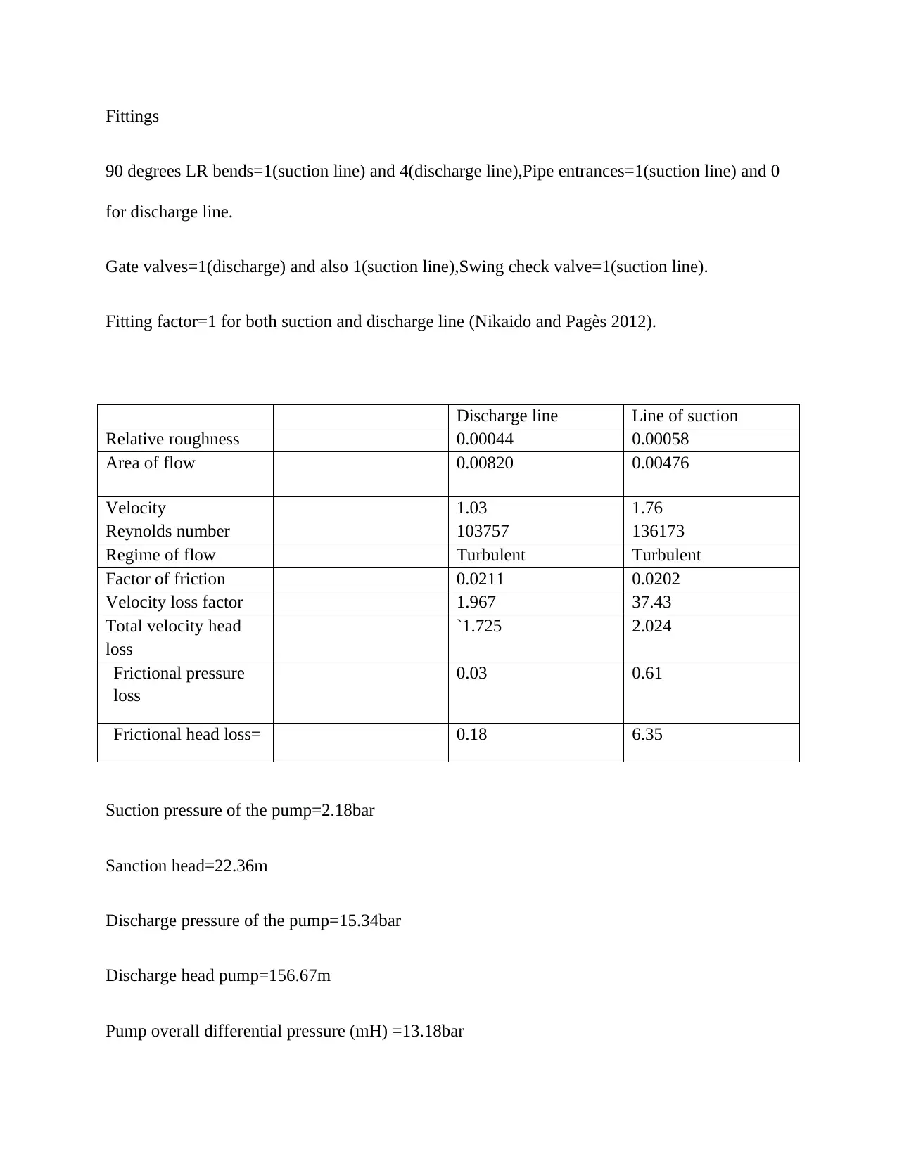
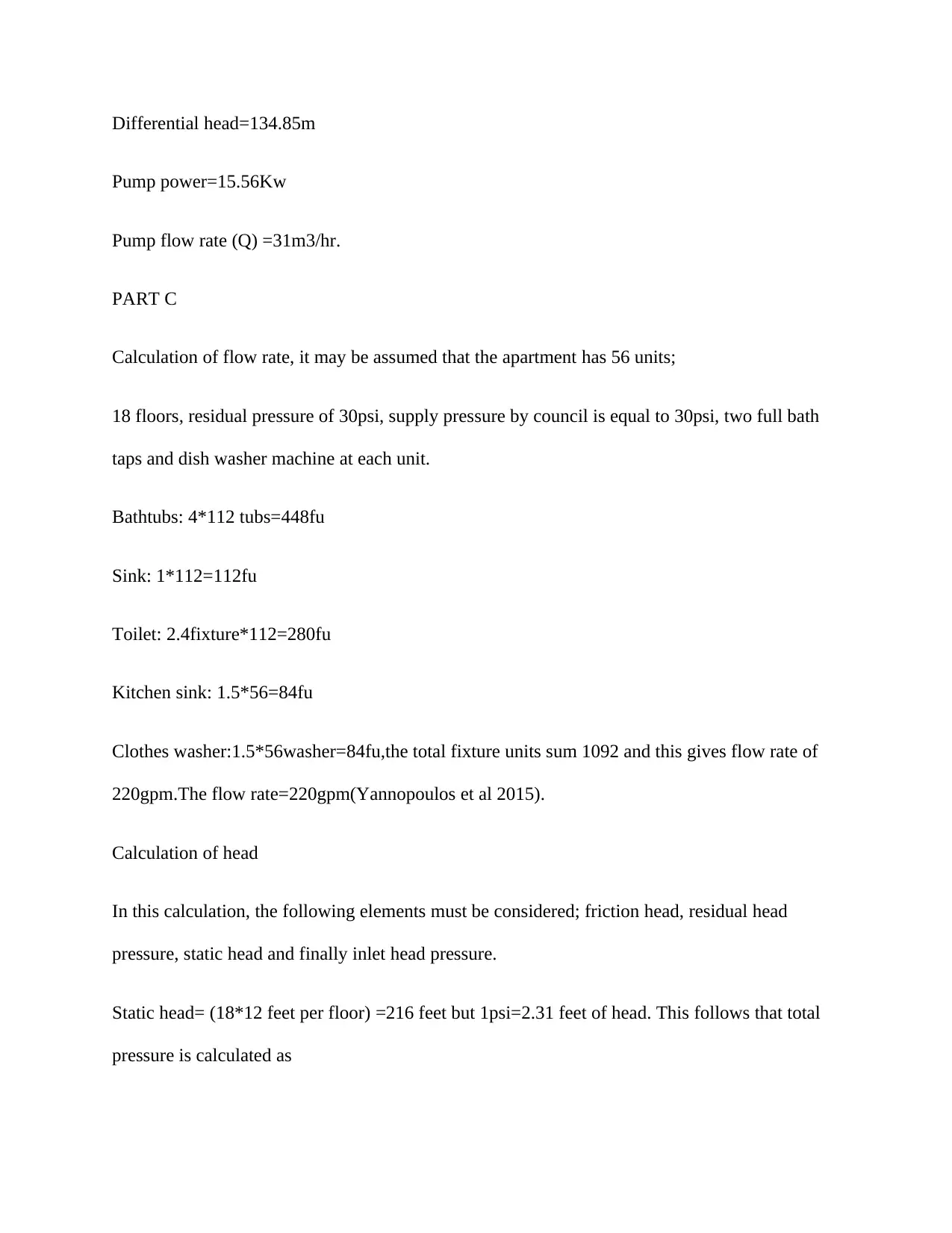
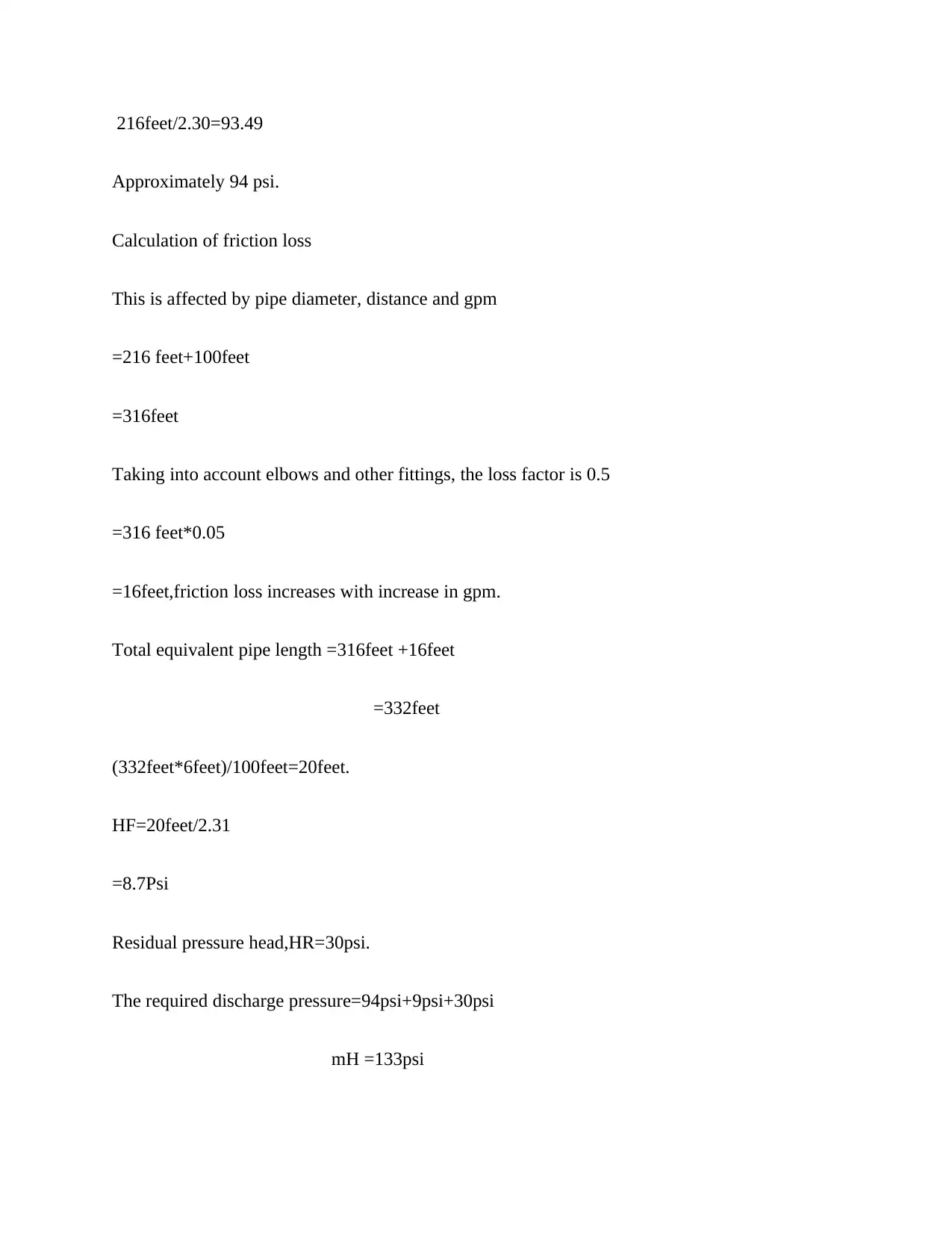
This document provides a comprehensive solution to a Construction Technology 6 assignment focused on hydraulic services for a proposed office development. The assignment encompasses several key aspects of building services design, including pump sizing calculations, determination of flow rates, and design considerations for both sanitary drainage and stormwater management. The solution details the process of sizing a pump, considering factors like flow rate, total differential head (including static and frictional head losses), and pump power. It includes calculations for both suction and discharge lines, taking into account pipe diameters, lengths, fittings, and fluid properties. Furthermore, the assignment addresses the calculation of flow rates for an apartment building, considering fixture units and head loss calculations. The stormwater section requires the design of a detention tank, considering rainfall intensity and local council regulations. The document references relevant standards, codes, and rainfall-runoff models, providing a detailed and practical approach to hydraulic services design in construction.
tabler-icon-diamond-filled.svg

Contribute Materials

Your contribution can guide someone’s learning journey. Share your documents today.
Document Page
CONSTRUCTION TECHNOLOGY 6
By Name
Course
Instructor
Institution
Location
Date
tabler-icon-diamond-filled.svg

Secure Best Marks with AI Grader

Need help grading? Try our AI Grader for instant feedback on your assignments.
Document Page
PART (B)
Pump sizing. `
In the process of sizing a pump, the following points must be given specific consideration;
Flow rate
This is normally obtained by the process through which the pump is installed. The mass and
energy balance of the process ultimately define the process.
Total differential head
Total differential head=Frictional head losses differences of static head.
Static head difference
It is the difference in the head between the suction static head and discharge static head; static
head difference=suction static head+discharge static head.
Static head
This is normally considered as the sum of the gas pressure at the liquid surface in the vessel of
discharge(Monteith et al 2012).
Frictional head losses
Frictional head losses consist of frictional losses in the piping system of the suction part and also
in the discharge piping system.
This is normally calculated using the formula below;
Document Page
Frictional head losses= (FL/D+Kfittings) u2/2g where;
F=friction factor
L= pipe length
D=diameter of pipe
K=fitting factor
U=velocity of the liquid
g=acceleration due to gravity.
Pump power
Pump power=flow rate*density of the liquid*acceleration due to gravity*efficiency of the
pump*total differential.
Assuming that the amount of water to be pumped is 30000kg/hr. from one tank to another, water
temperature is at 20c,density of 998kg/m3,vapour pressure of 0.023 bar and a viscosity of
1cp.The efficiency of the pump is taken to be 70%( Sun, Deng and Yan 2014).
Details of the pump
Barometric pressure=1.013bar
Margin available=0m
Efficiency of the pump=70%
Properties of the fluid
Document Page
Type of fluid=water
Phase of the fluid=liquid
Flow rate=30000kg/hr.
Liquid density=998kg/m3
Water viscosity=1cP
Vapor pressure=0.023bar
Gas pressure vessels
Suction gas pressure=1bar
Gas pressure of discharge=2bar
Static heads
Static head at suction=2m
Static head at discharge=120m
Pipelines
Nominal diameter pipe=4(suction line) and 3(discharge line).
Pipe schedule=40(for both suction line and discharge line)
Length of the pipe=150m (discharge line) and 10m for suction line.
Absolute roughness=0.046m for both suction and discharge line.
tabler-icon-diamond-filled.svg

Secure Best Marks with AI Grader

Need help grading? Try our AI Grader for instant feedback on your assignments.
Document Page
Fittings
90 degrees LR bends=1(suction line) and 4(discharge line),Pipe entrances=1(suction line) and 0
for discharge line.
Gate valves=1(discharge) and also 1(suction line),Swing check valve=1(suction line).
Fitting factor=1 for both suction and discharge line (Nikaido and Pagès 2012).
Discharge line Line of suction
Relative roughness 0.00044 0.00058
Area of flow 0.00820 0.00476
Velocity
Reynolds number
1.03
103757
1.76
136173
Regime of flow Turbulent Turbulent
Factor of friction 0.0211 0.0202
Velocity loss factor 1.967 37.43
Total velocity head
loss
`1.725 2.024
Frictional pressure
loss
0.03 0.61
Frictional head loss= 0.18 6.35
Suction pressure of the pump=2.18bar
Sanction head=22.36m
Discharge pressure of the pump=15.34bar
Discharge head pump=156.67m
Pump overall differential pressure (mH) =13.18bar
Document Page
Differential head=134.85m
Pump power=15.56Kw
Pump flow rate (Q) =31m3/hr.
PART C
Calculation of flow rate, it may be assumed that the apartment has 56 units;
18 floors, residual pressure of 30psi, supply pressure by council is equal to 30psi, two full bath
taps and dish washer machine at each unit.
Bathtubs: 4*112 tubs=448fu
Sink: 1*112=112fu
Toilet: 2.4fixture*112=280fu
Kitchen sink: 1.5*56=84fu
Clothes washer:1.5*56washer=84fu,the total fixture units sum 1092 and this gives flow rate of
220gpm.The flow rate=220gpm(Yannopoulos et al 2015).
Calculation of head
In this calculation, the following elements must be considered; friction head, residual head
pressure, static head and finally inlet head pressure.
Static head= (18*12 feet per floor) =216 feet but 1psi=2.31 feet of head. This follows that total
pressure is calculated as
Document Page
216feet/2.30=93.49
Approximately 94 psi.
Calculation of friction loss
This is affected by pipe diameter, distance and gpm
=216 feet+100feet
=316feet
Taking into account elbows and other fittings, the loss factor is 0.5
=316 feet*0.05
=16feet,friction loss increases with increase in gpm.
Total equivalent pipe length =316feet +16feet
=332feet
(332feet*6feet)/100feet=20feet.
HF=20feet/2.31
=8.7Psi
Residual pressure head,HR=30psi.
The required discharge pressure=94psi+9psi+30psi
mH =133psi
tabler-icon-diamond-filled.svg

Paraphrase This Document

Need a fresh take? Get an instant paraphrase of this document with our AI Paraphraser
Document Page
REFERENCES
Nikaido, H. and Pagès, J.M., 2012. Broad-specificity efflux pumps and their role in multidrug
resistance of Gram-negative bacteria. FEMS microbiology reviews, 36(2), pp.340-363.
Monteith, G.R., Davis, F.M. and Roberts-Thomson, S.J., 2012. Calcium channels and pumps in
cancer: changes and consequences. Journal of Biological Chemistry, 287(38), pp.31666-31673.
Sun, J., Deng, Z. and Yan, A., 2014. Bacterial multidrug efflux pumps: mechanisms, physiology
and pharmacological exploitations. Biochemical and biophysical research
communications, 453(2), pp.254-267.
Yannopoulos, S.I., Lyberatos, G., Theodossiou, N., Li, W., Valipour, M., Tamburrino, A. and
Angelakis, A.N., 2015. Evolution of water lifting devices (pumps) over the centuries
worldwide. Water, 7(9), pp.5031-5060.
chevron_up_icon
1 out of 8
circle_padding
hide_on_mobile
zoom_out_icon
logo.png

Your All-in-One AI-Powered Toolkit for Academic Success.

Available 24*7 on WhatsApp / Email

[object Object]