Control Systems Assignment: Analysis of Control Systems and Components

Verified

Added on  2023/01/19

|8
|802
|35
Homework Assignment
AI Summary
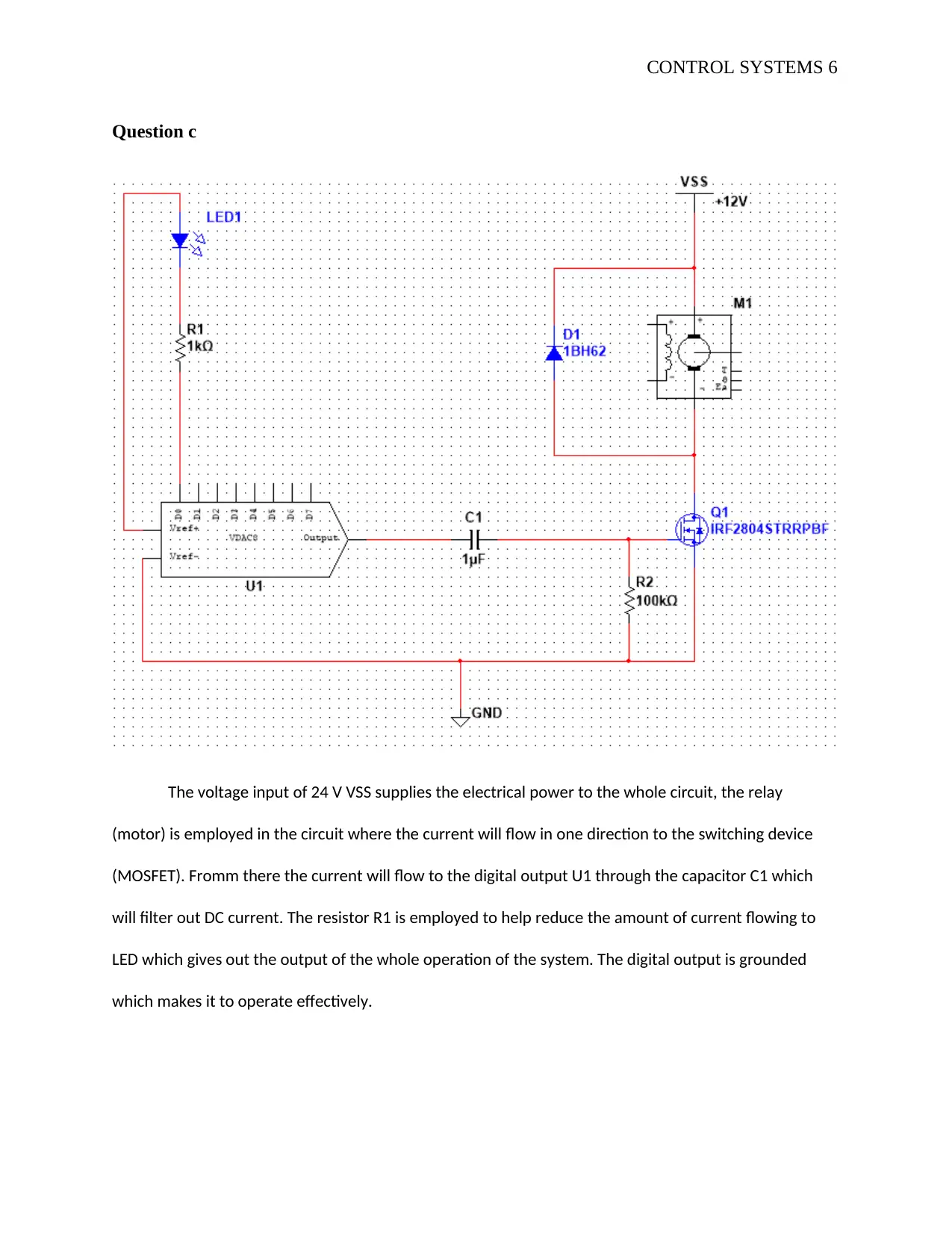
This document presents a comprehensive solution to a Control Systems assignment. It begins by differentiating between open-loop and closed-loop control systems, providing examples of each. The assignment then delves into the functionality of absolute and incremental rotary encoders, including diagrams illustrating their operation. Furthermore, the solution analyzes a specific circuit, detailing the roles of various components such as the MOSFET, capacitor, and resistor, and explaining how they function within the circuit. Finally, the document discusses protective electronic devices, specifically diodes and capacitors, and explains their importance in safeguarding circuits from damage. This assignment provides a detailed overview of essential control systems concepts and practical circuit analysis.
tabler-icon-diamond-filled.svg

Contribute Materials

Your contribution can guide someone’s learning journey. Share your documents today.
Document Page
CONTROL SYSTEMS 1
CONTROL SYSTEMS
By Name
Course
Instructor
Institution
Location
Date
tabler-icon-diamond-filled.svg

Secure Best Marks with AI Grader

Need help grading? Try our AI Grader for instant feedback on your assignments.
Document Page
CONTROL SYSTEMS 2
Question a
The open-loop control system
This is any physical which doesn´t automatically correct the variation in its output. And it can be
given by the following diagram
An example may include the following
i. Traffic controlled by a traffic signal.
ii. The sequence of time of control signal is based on the time given for each signal.
iii. The time slots are decided based on a traffic study
iv. The traffic will not measure the density of the traffic before giving the signal
v. Since the time slot doesn’t change the accuracy to traffic density, the signal is known
as an open loop control system.
The closed loop control system
This is a control system in which the output has an effect upon the input quality and in such an
aim to maintain the desired output value is called closed loop control system (Gopal, 2011). And
the example of such a control system is given below;
Document Page
CONTROL SYSTEMS 3
Air conditioning with auto cutoff.
Temperature control system
The switching On/OFF of the relay is controlled by a controller that is a digital system, for
example, a computer. The actual temperature is sensed by the sensor corresponding to the
desired temperature (Gopal, 2011). The relay will turn ON/OFF to the desired temperature which
is not equal to the actual temperature.
Document Page
CONTROL SYSTEMS 4
Question b
Absolute rotary encoder
This type of encoder is capable of giving a unique position value from the time this encoder is
switched on. This will be realized by scanning the coded element position. Every position here
corresponds to a unique code. The moments which happens while the encoder is off will also be
translated into precise position value as long as the system is powered again. The encoder can be
illustrated using the diagram below;
Figure 1: Showing absolute rotary encoder
Incremental Rotary Encoders
This type of encoder produces an output signal for every time there is a rotation of the shaft for a
specified amount of rotation. For every moment the encoder is powered ON, the encoder will
start counting from zero notwithstanding of where the shaft is situated. Such types are available
tabler-icon-diamond-filled.svg

Secure Best Marks with AI Grader

Need help grading? Try our AI Grader for instant feedback on your assignments.
Document Page
CONTROL SYSTEMS 5
for several configurations like A, B, Z but the inverted signals are available as TTL (RS422) or
even Push Pull( HTL). It can be given by the following diagram
Figure 2: Showing incremental rotary encoder
From the above analysis of the two common types of the encoder, we can say that CL3 E will
support the incremental rotary encoder. This is because CL3 E has configurations like A, B, Z
but the inverted signals are available as TTL (RS422) or even Push Pull (HTL).
Document Page
CONTROL SYSTEMS 6
Question c
The voltage input of 24 V VSS supplies the electrical power to the whole circuit, the relay
(motor) is employed in the circuit where the current will flow in one direction to the switching device
(MOSFET). Fromm there the current will flow to the digital output U1 through the capacitor C1 which
will filter out DC current. The resistor R1 is employed to help reduce the amount of current flowing to
LED which gives out the output of the whole operation of the system. The digital output is grounded
which makes it to operate effectively.
Document Page
CONTROL SYSTEMS 7
Question d
There are several electronic devices which can be employed for protection, they can
include diode, capacitor and resistors. For a circuit diagram like the one given in part c above
diode is used as a protective device since it only allows the current to flow in unidirectional there
will be no power surges which can make the electronics components to blow. While the
capacitor is used to help block the DC from flowing in the circuit, this is because the DC cannot
pass through the capacitor. DC current always sees the capacitor as an open circuit since there is
no electrical connection. It is also good to filter out DC current because the circuit will contain
both the DC and the AC current.
tabler-icon-diamond-filled.svg

Paraphrase This Document

Need a fresh take? Get an instant paraphrase of this document with our AI Paraphraser
Document Page
CONTROL SYSTEMS 8
Bibliography
Bakshi, U., 2010. Feedback Control Systems. 3rd ed. Liverpool: Technical Publications.
Gopal, M., 2011. Control Systems: Principles and Design. 3rd ed. Hull: Tata McGraw-Hill Education.
chevron_up_icon
1 out of 8
circle_padding
hide_on_mobile
zoom_out_icon
logo.png

Your All-in-One AI-Powered Toolkit for Academic Success.

Available 24*7 on WhatsApp / Email

[object Object]