Control Systems: Feedback Analysis and Design - Assignment

Verified

Added on  2023/03/30

|19
|1966
|295
Homework Assignment
AI Summary
This document provides a comprehensive solution to a control feedback analysis assignment. The solution covers various aspects of control systems, including the analysis and design of feedback loops. It begins with determining system parameters (k and p) based on step response characteristics, such as settling time and overshoot. The assignment then delves into closed-loop transfer functions with additional feedback signals and investigates the impact of gain parameters (k1 and k2) on system performance. The document includes calculations and analysis of steady-state error, alongside the use of Laplace transforms to model system behavior. Furthermore, the solution incorporates Nyquist and Bode plots, demonstrating stability analysis and the application of compensators. The MATLAB code is provided, demonstrating the simulation and analysis of the control systems and the impact of different control strategies on system performance, including calculations of gain and phase margins. The solution also includes the application of compensators, providing a thorough understanding of control system design.
Document Page
Running head: CONTROL FEEDBACK 1
Control Feedback
Name
Institution
tabler-icon-diamond-filled.svg

Paraphrase This Document

Need a fresh take? Get an instant paraphrase of this document with our AI Paraphraser
Document Page
CONTROL FEEDBACK 2
Control Feedback
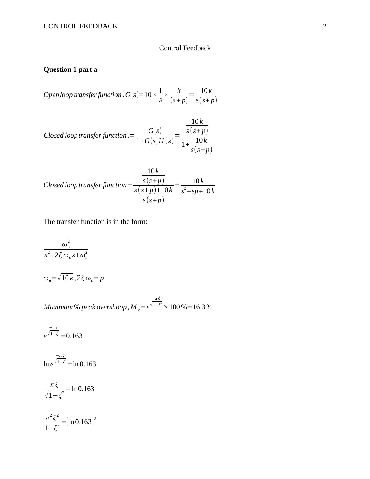
Question 1 part a
Openloop transfer function ,G ( s )=10 × 1
s × k
(s + p) = 10 k
s( s+ p)
Closed looptransfer function ,= G ( s )
1+G ( s ) H (s)=
10 k
s ( s+ p)
1+ 10 k
s(s + p)
Closed looptransfer function=
10 k
s (s + p)
s (s+ p)+10 k
s (s + p)
= 10 k
s2 +sp+10 k
The transfer function is in the form:
ωn
2
s2+ 2ζ ωn s+ωn
2
ωn= 10 k , 2ζ ωn= p
Maximum % peak overshoop , M p=e
π ζ
1ζ 2
× 100 %=16.3 %
e
π ζ
1ζ 2
=0.163
ln e
π ζ
1ζ 2
=ln 0.163
π ζ
1ζ2 =ln 0.163
π2 ζ2
1ζ2 = ( ln0.163 )2
Document Page
CONTROL FEEDBACK 3
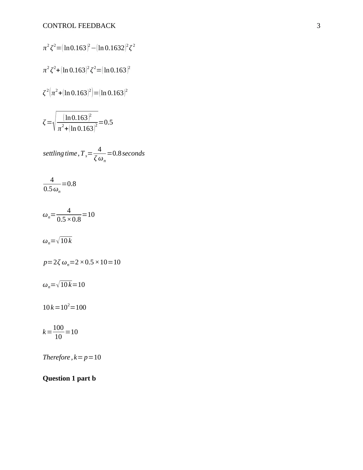
π2 ζ2= ( ln0.163 )2 ( ln 0.1632 ) 2 ζ 2
π2 ζ2+ ( ln 0.163 ) 2 ζ 2= ( ln 0.163 )2
ζ 2 ( π2 + ( ln 0.163 )2 )= ( ln 0.163 )2
ζ = ( ln 0.163 )2
π2 + ( ln 0.163 )2 =0.5
settling time, T s= 4
ζ ωn
=0.8 seconds
4
0.5 ωn
=0.8
ωn= 4
0.5 ×0.8 =10
ωn= 10 k
p=2ζ ωn=2 ×0.5 ×10=10
ωn= 10 k=10
10 k =102=100
k =100
10 =10
Therefore , k= p=10
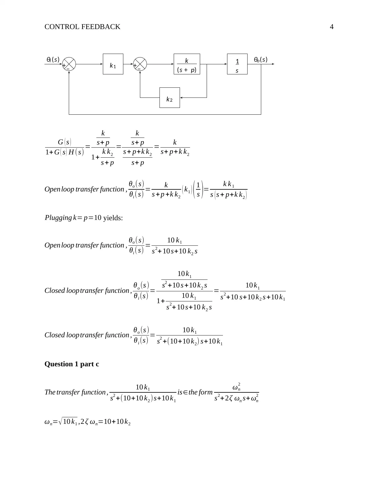
Question 1 part b
Document Page
CONTROL FEEDBACK 4
G ( s )
1+ G ( s ) H (s) =
k
s+ p
1+ k k2
s + p
=
k
s+ p
s + p+k k2
s+ p
= k
s+ p+k k2
Openloop transfer function , θo (s)
θi ( s) = k
s +p +k k2
( k1 ) ( 1
s )= k k 1
s ( s + p+k k2 )
Plugging k= p=10 yields:
Openloop transfer function , θo (s)
θi ( s) = 10 k1
s2+ 10 s+10 k2 s
Closed looptransfer function , θo (s )
θi (s) =
10 k1
s2 +10 s +10 k2 s
1+ 10 k1
s2+ 10 s+10 k2 s
= 10 k1
s2+10 s+10 k2 s +10 k1
Closed looptransfer function , θo (s )
θi (s) = 10 k1
s2 +(10+10 k2) s+10 k1
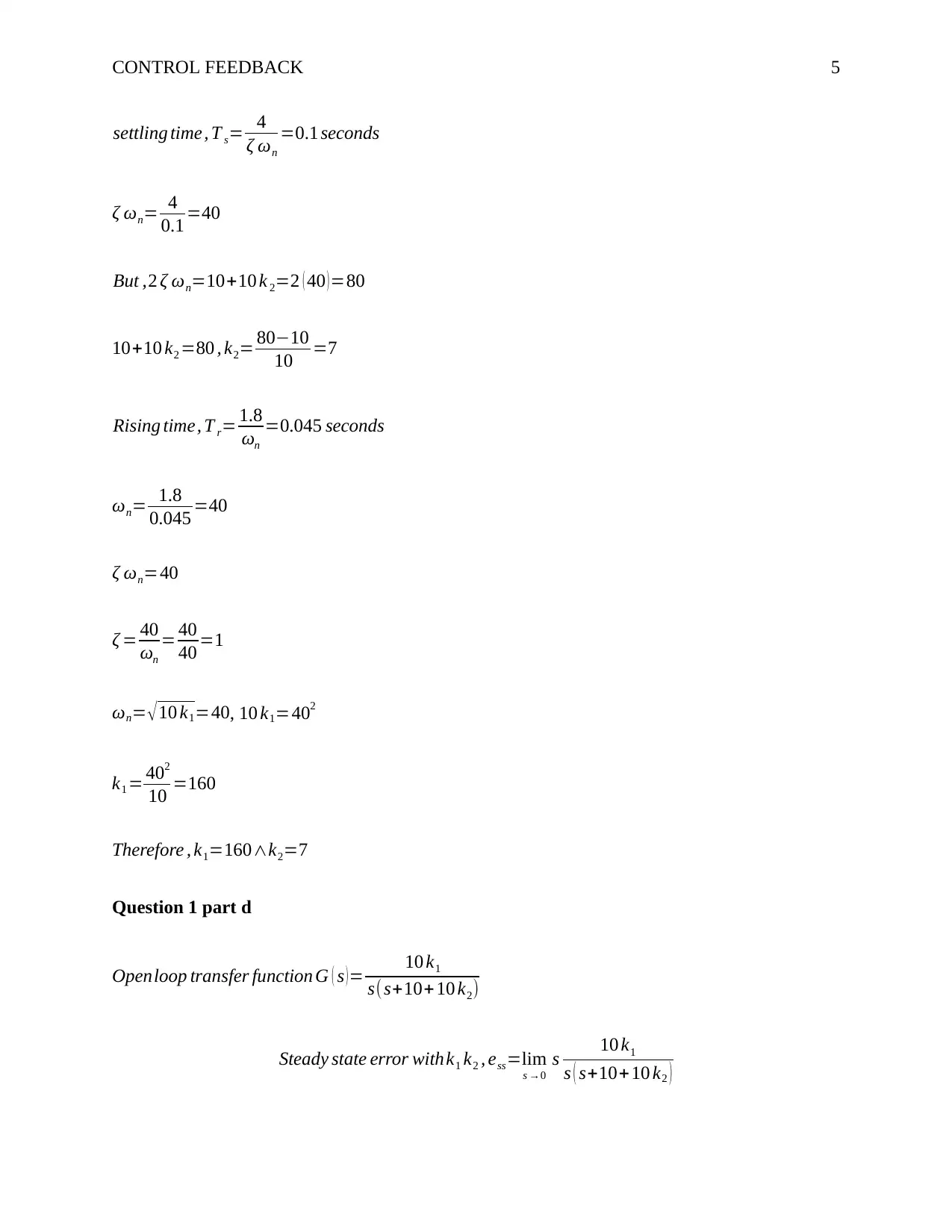
Question 1 part c
The transfer function , 10 k1
s2 +(10+10 k2 )s+10 k1
isthe form ωn
2
s2+ 2ζ ωn s+ ωn
2
ωn= 10 k1 ,2 ζ ωn=10+10 k2

+
θi (s) k1
+ k
(s + p)
k2
1
s
θo(s)
tabler-icon-diamond-filled.svg

Paraphrase This Document

Need a fresh take? Get an instant paraphrase of this document with our AI Paraphraser
Document Page
CONTROL FEEDBACK 5
settling time, T s= 4
ζ ωn
=0.1 seconds
ζ ωn= 4
0.1 =40
But ,2 ζ ωn=10+10 k 2=2 ( 40 )=80
10+10 k2 =80 , k2= 8010
10 =7
Rising time, T r= 1.8
ωn
=0.045 seconds
ωn= 1.8
0.045 =40
ζ ωn=40
ζ = 40
ωn
= 40
40 =1
ωn= 10 k1=40, 10 k1=402
k1 = 402
10 =160
Therefore , k1=160k2=7
Question 1 part d
Openloop transfer function G ( s ) = 10 k1
s(s+10+ 10 k2)
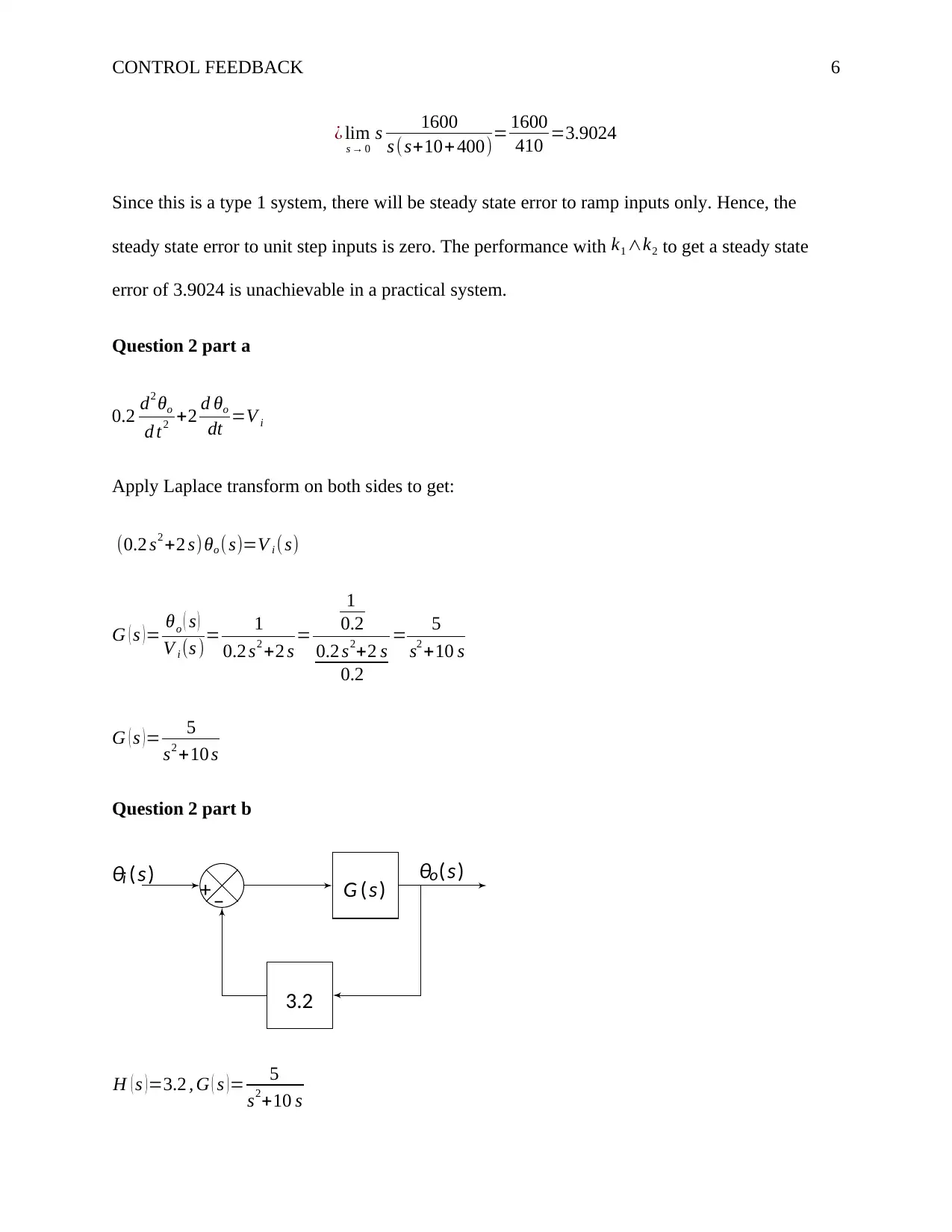
Steady state error withk1 k2 , ess=lim
s 0
s 10 k1
s ( s+10+10 k2 )
Document Page
CONTROL FEEDBACK 6
¿ lim
s 0
s 1600
s ( s+10+ 400)= 1600
410 =3.9024
Since this is a type 1 system, there will be steady state error to ramp inputs only. Hence, the
steady state error to unit step inputs is zero. The performance with k1 k2 to get a steady state
error of 3.9024 is unachievable in a practical system.
Question 2 part a
0.2 d2 θo
d t2 +2 d θo
dt =V i
Apply Laplace transform on both sides to get:
(0.2 s2 +2 s)θo (s)=V i (s)
G ( s ) = θo ( s )
V i (s )= 1
0.2 s2 +2 s =
1
0.2
0.2 s2+2 s
0.2
= 5
s2 +10 s
G ( s )= 5
s2 +10 s
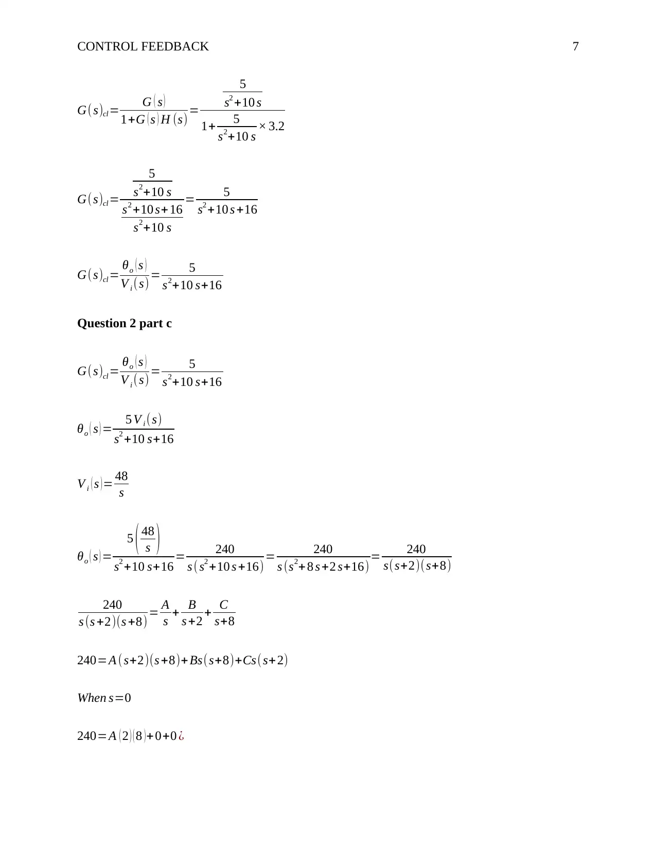
Question 2 part b
H ( s )=3.2 , G ( s )= 5
s2+10 s

+ G (s)
3.2
θi (s) θo(s)
Document Page
CONTROL FEEDBACK 7
G(s)cl = G ( s )
1+G ( s ) H (s)=
5
s2 +10 s
1+ 5
s2+10 s × 3.2
G(s)cl =
5
s2+10 s
s2 +10 s+ 16
s2+10 s
= 5
s2 +10 s +16
G(s)cl = θo ( s )
V i (s)= 5
s2+10 s+16
Question 2 part c
G(s)cl = θo ( s )
V i (s)= 5
s2+10 s+16
θo ( s ) = 5 V i (s)
s2 +10 s+16
V i ( s )= 48
s
θo ( s ) =
5 ( 48
s )
s2 +10 s+16 = 240
s ( s2 +10 s +16) = 240
s (s2+ 8 s +2 s+16)= 240
s(s+2)(s+8)
240
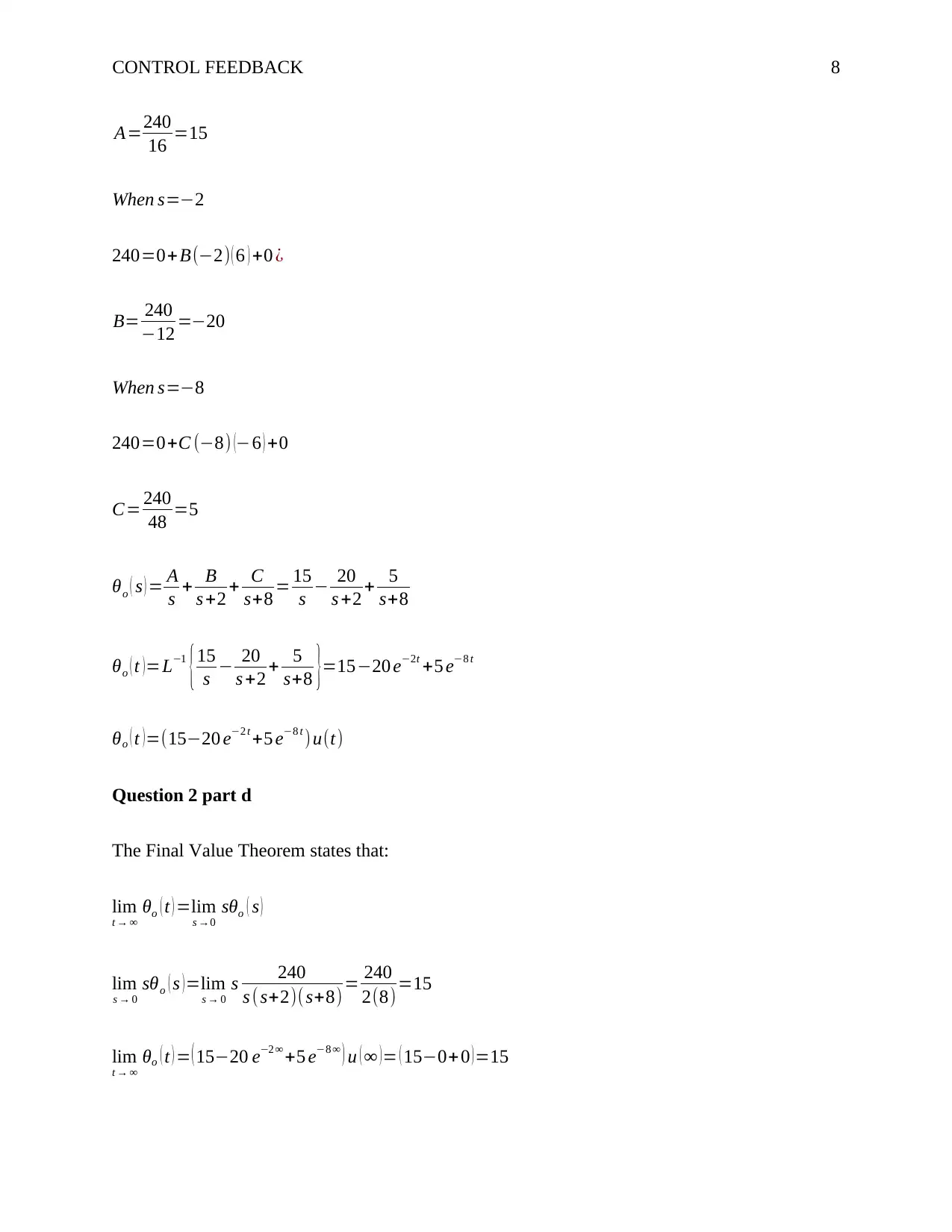
s (s +2)(s +8) = A
s + B
s +2 + C
s+8
240=A ( s+2)(s +8)+ Bs(s+8)+Cs( s+2)
When s=0
240=A ( 2 ) ( 8 )+ 0+0 ¿
tabler-icon-diamond-filled.svg

Paraphrase This Document

Need a fresh take? Get an instant paraphrase of this document with our AI Paraphraser
Document Page
CONTROL FEEDBACK 8
A=240
16 =15
When s=2
240=0+ B(2) ( 6 ) +0 ¿
B= 240
12 =20
When s=8
240=0+C (8) (6 ) +0
C= 240
48 =5
θo ( s ) = A
s + B
s +2 + C
s+8 = 15
s 20
s +2 + 5
s+8
θo ( t )=L1
{15
s 20
s +2 + 5
s+8 }=1520 e2t +5 e8 t
θo ( t ) =(1520 e2 t +5 e8 t )u(t)
Question 2 part d
The Final Value Theorem states that:
lim
t
θo ( t ) =lim
s 0
o ( s )
lim
s 0
o ( s ) =lim
s 0
s 240
s (s+2)( s+8)= 240
2(8)=15
lim
t
θo ( t ) = ( 1520 e2 +5 e8 ) u ( )= ( 150+0 )=15
Document Page
CONTROL FEEDBACK 9
Therefore , lim
t
θo ( t )=lim
s 0
o ( s )
The steady output does not match the input in part (c) because the servomechanism does not
have a unity feedback.
Question 2 part e
Increasing the gain parameters from 3.2 increases the response of the system. However,
increasing the value beyond a particular safety zone could make the system unstable. Introducing
an integral and differential control into the system could increase the steady-state output for the
same magnitude input step without affecting response speed.
Question 3 part a
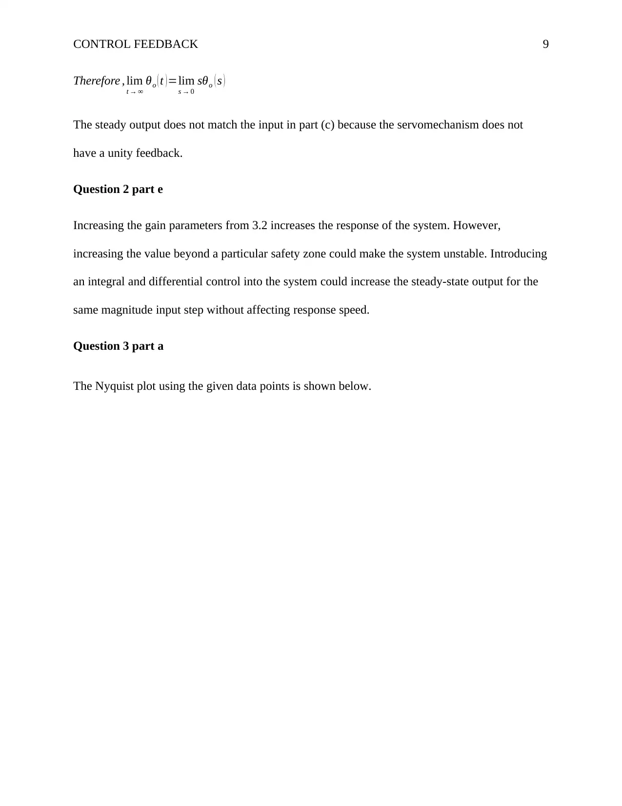
The Nyquist plot using the given data points is shown below.
Document Page
CONTROL FEEDBACK 10
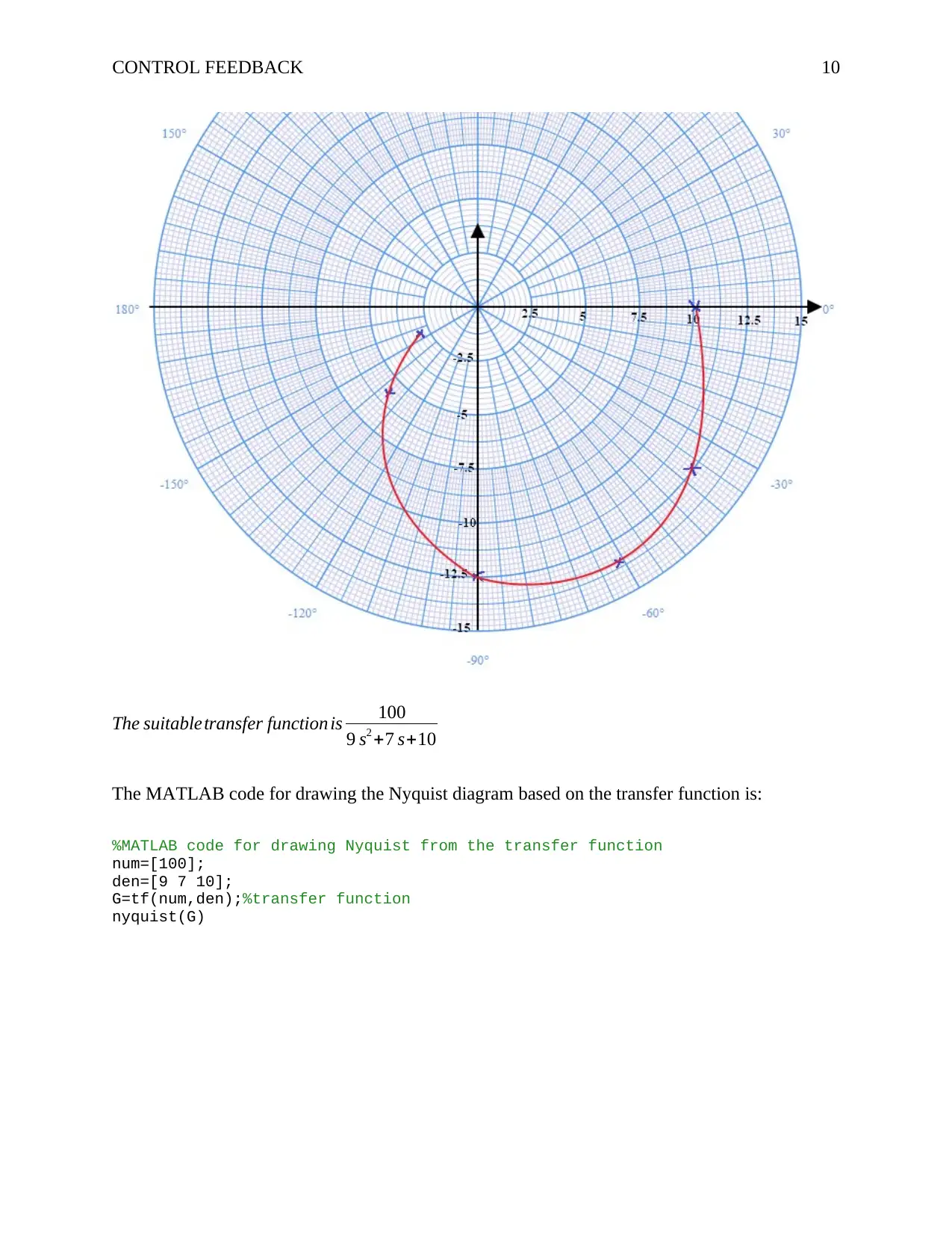
The suitabletransfer function is 100
9 s2 +7 s+10
The MATLAB code for drawing the Nyquist diagram based on the transfer function is:
%MATLAB code for drawing Nyquist from the transfer function
num=[100];
den=[9 7 10];
G=tf(num,den);%transfer function
nyquist(G)
tabler-icon-diamond-filled.svg

Paraphrase This Document

Need a fresh take? Get an instant paraphrase of this document with our AI Paraphraser
Document Page
CONTROL FEEDBACK 11
Question 3 part b
Transfer function= 100
9 ω2 + j 7 ω +10 = 100
( 109 ω2 ) + j 7 ω
The magnitude=20 log 100
( 109 ω2 )2
+49 ω2
dB
The phase of the system=tan1
( 7 ω
109 ω2 )
%MATLAB code for calculating magnitude and phase
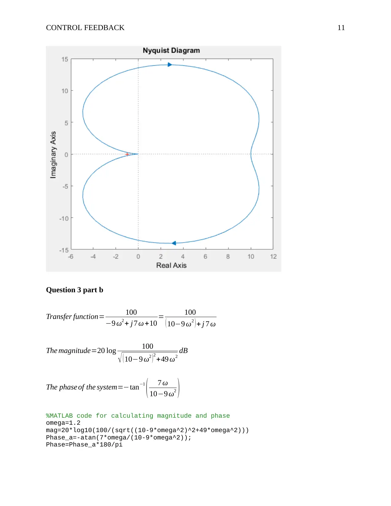
omega=1.2
mag=20*log10(100/(sqrt((10-9*omega^2)^2+49*omega^2)))
Phase_a=-atan(7*omega/(10-9*omega^2));
Phase=Phase_a*180/pi
Document Page
CONTROL FEEDBACK 12
Running the MATLAB code gives the results below :
Question 3 part c
The closed loop system will have a pole on the negative half s-plane making it instable.
k = 5 would give a phase margin of 30◦.
chevron_up_icon
1 out of 19
circle_padding
hide_on_mobile
zoom_out_icon
[object Object]