University Project: ETEN6000 Control Systems Design and Analysis

Verified

Added on  2021/06/17

|10
|1438
|23
Project
AI Summary
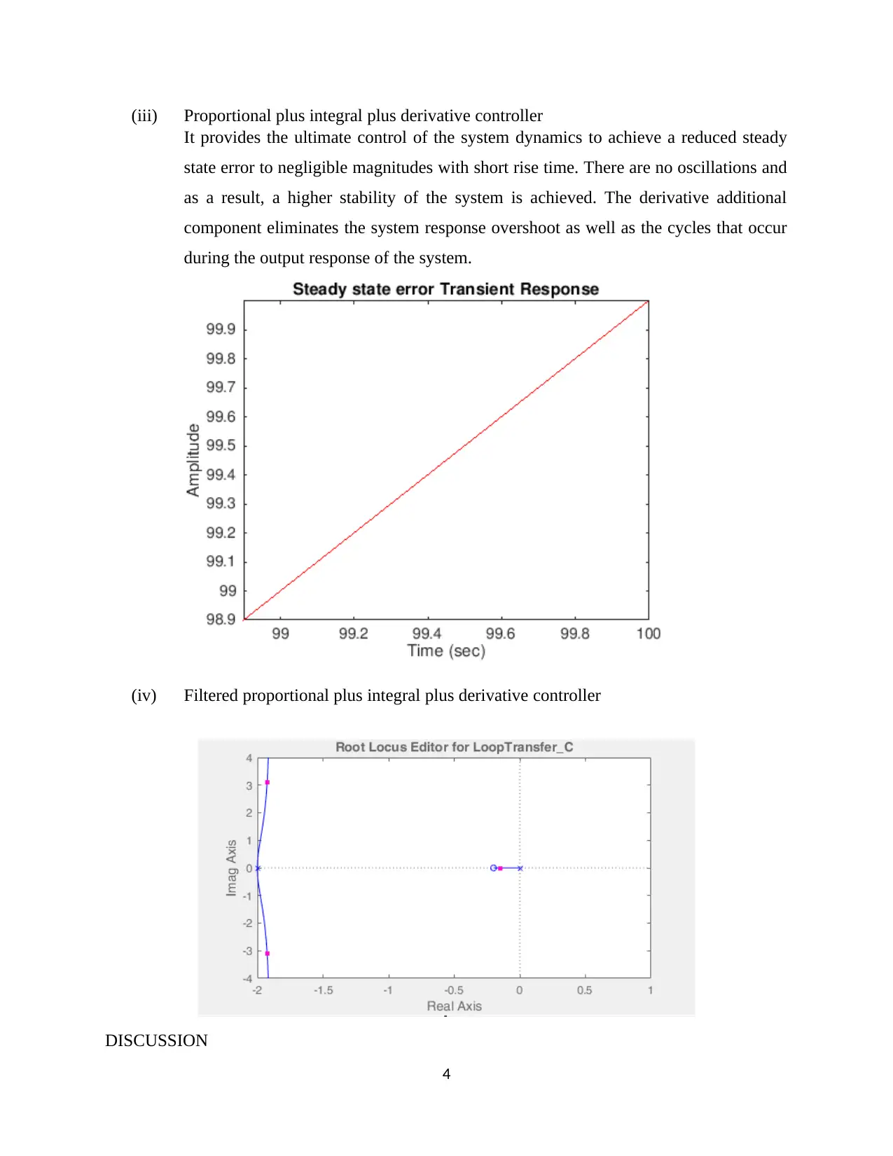
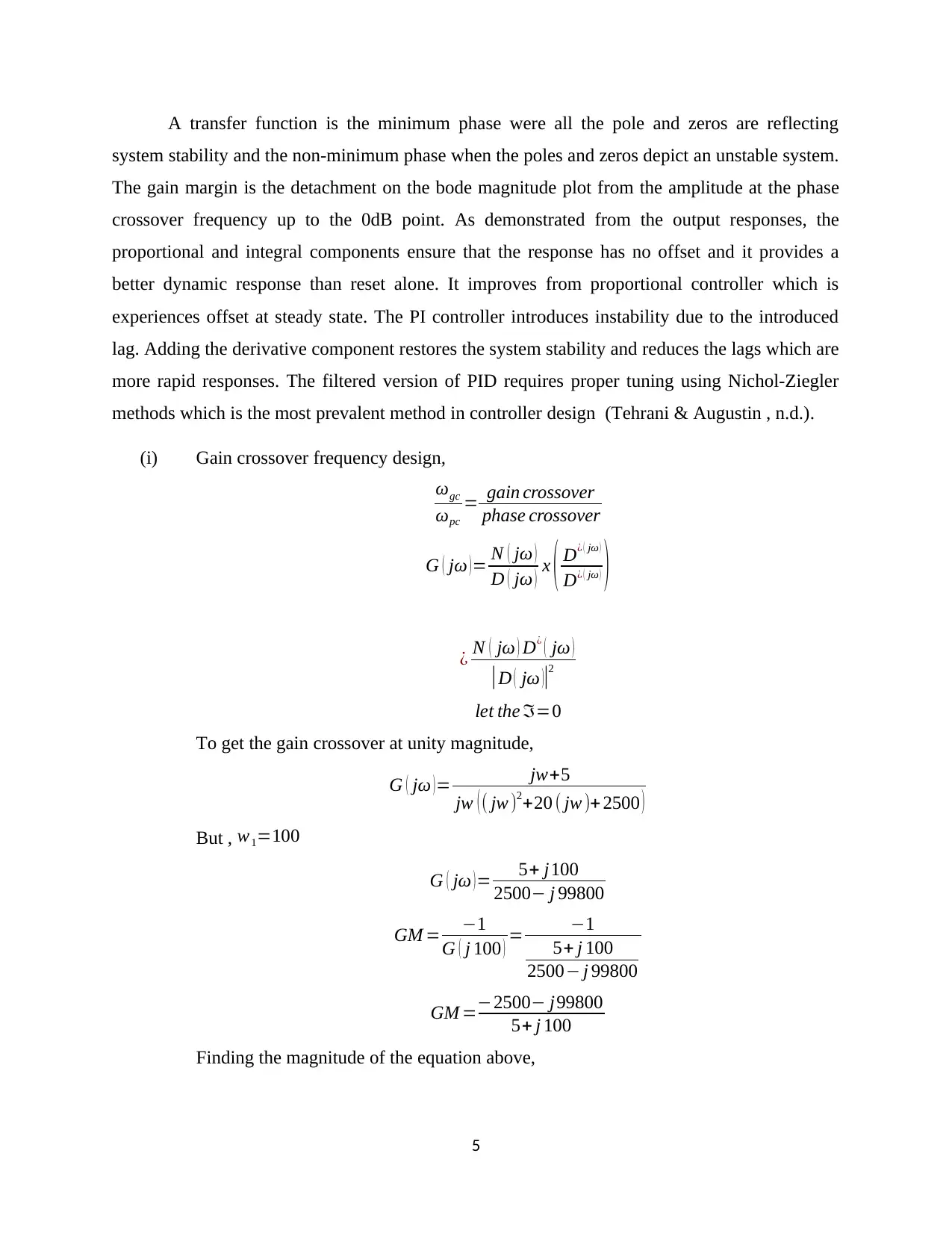
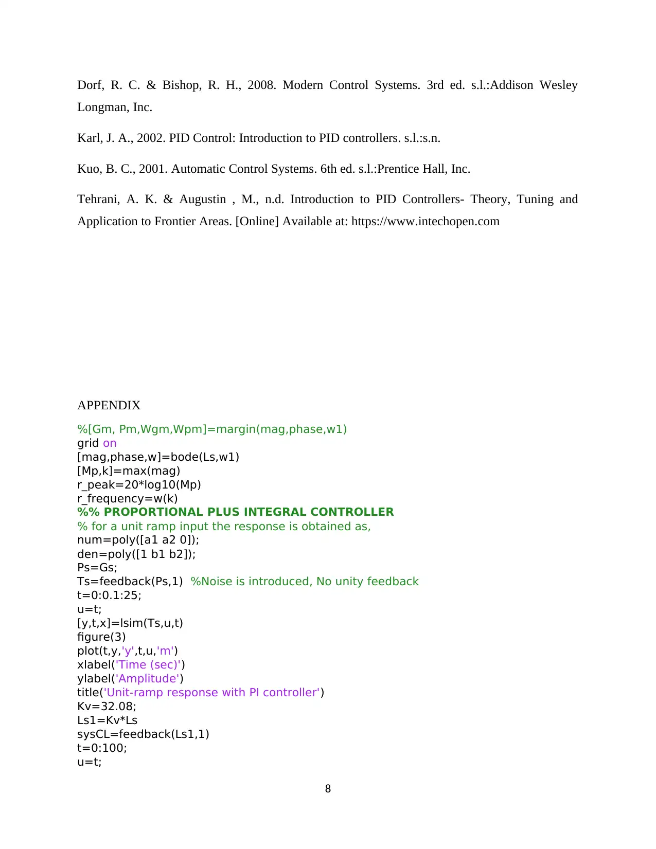
This project report focuses on the design and analysis of control systems, specifically addressing the application of proportional, integral, and derivative (PID) controllers. The project begins with an introduction to control systems, highlighting their importance in industrial applications and the use of feedback loops to achieve desired outputs. The report then outlines the design specifications, including gain crossover frequency, steady-state error, and phase margin. The core of the project involves the analysis of proportional, proportional-integral (PI), and proportional-integral-derivative (PID) controllers, including their effects on system stability, steady-state error, and transient response. The report discusses the merits and limitations of each controller type, including their impact on signal rise time, overshoot, and noise sensitivity. The design process includes mathematical derivations, bode plots, and simulations using MATLAB to meet the design criteria. The project concludes with a discussion of the results, comparing the performance of different controllers and emphasizing the importance of proper tuning. The report includes MATLAB code and analysis of a ramp input response and a discussion of the transfer function, gain margin, and the implementation of PI controllers. The project aims to provide a comprehensive understanding of control system design principles and practical implementation, offering insights into improving system performance and stability.
Document Page
UNIVERSITY AFFILIATION
ETEN6000 CONTROL SYSTEMS
DESIGN ASSIGNMENT
TITLE:
STUDENT NAME
STUDENT REGISTRATION NUMBER
PROFESSOR (TUTOR)
DATE OF SUBMISSION
INTRODUCTION
MAY 19, 2018
tabler-icon-diamond-filled.svg

Paraphrase This Document

Need a fresh take? Get an instant paraphrase of this document with our AI Paraphraser
Document Page
Controllers in linear time-invariant systems are used to ensure that the intended output is yielded
despite the errors and disturbances in the surrounding. The control systems are used in industrial
applications as they tend to improve the manufacturing processes, the efficiency of energy usage,
advanced automobile control which includes the rapid transport alongside other merits (Dorf &
Bishop, 2008). The controllers use an iterative approach to get the accurate output. The iterative
approach is achieved using the feedback loop which enables the summer to compute the error by
comparing the actual output to the input. Some systems have very complex plants which need to
be controlled hence the controller should be designed appropriately.
The controller seeks to ensure that the intended output of the process, G(s), is obtained despite
the effects of the noise signal at the feedback loop. The variables that need to be controlled are
the gain crossover frequency, steady state error, phase margin, and the noise measure. A closed
loop system has a feedback loop that aims at enabling modification of the system behavior (Kuo,
2001). The impact of the feedback loop is to ensure that the desired output is obtained from the
system. The loop takes back the actual output to the summer to check for errors and the output
signal from the summer is taken into a controller for appropriate adjustment. The feedback loop
performs the measurement and signal transmission of the system.
DESIGN SPEFICATIONS
(i) The gain crossover frequency should be, ωc=ω1
(ii) The steady state error ought to be zero in response to a unit ramp reference
(iii) The phase margin should be at least 600
(iv) The effect of measurement noise on the output should be attenuated by at least 1/100
at noise frequencies, ω=ω2
RESULTS AND DISCUSSION
(i) Proportional controller
1
Document Page
It is applied to first order process systems that have a solitary energy storage to
stabilize the unstable process. The system is set up to reduce the steady state error. An
increase in the proportional constant decreases the steady state error of the system.
Unfortunately, the controller reduces but does not remove the steady state error. Some
of the merits associated with the proportional constant gain are small signal
amplitudes and phase margins, the dynamic attributes of the system have a wider
frequency bands and larger sensitivity to noise (Karl, 2002). It decreases the signal
rise time up to a certain value. Adding the value of Kp after that could lead to
overshoot of the system response and amplifies the process noise.
2
Document Page
(ii) Proportional plus integral controller
The P-I controller seeks to eliminate the steady state error that results from using
proportional gain constant. Unfortunately, the PI controller affects the system stability
and decreases the speed of response. It does not predict future errors in the system
and cannot decrease the rise time nor eliminate the oscillations.
3
tabler-icon-diamond-filled.svg

Paraphrase This Document

Need a fresh take? Get an instant paraphrase of this document with our AI Paraphraser
Document Page
(iii) Proportional plus integral plus derivative controller
It provides the ultimate control of the system dynamics to achieve a reduced steady
state error to negligible magnitudes with short rise time. There are no oscillations and
as a result, a higher stability of the system is achieved. The derivative additional
component eliminates the system response overshoot as well as the cycles that occur
during the output response of the system.
(iv) Filtered proportional plus integral plus derivative controller
DISCUSSION
4
Document Page
A transfer function is the minimum phase were all the pole and zeros are reflecting
system stability and the non-minimum phase when the poles and zeros depict an unstable system.
The gain margin is the detachment on the bode magnitude plot from the amplitude at the phase
crossover frequency up to the 0dB point. As demonstrated from the output responses, the
proportional and integral components ensure that the response has no offset and it provides a
better dynamic response than reset alone. It improves from proportional controller which is
experiences offset at steady state. The PI controller introduces instability due to the introduced
lag. Adding the derivative component restores the system stability and reduces the lags which are
more rapid responses. The filtered version of PID requires proper tuning using Nichol-Ziegler
methods which is the most prevalent method in controller design (Tehrani & Augustin , n.d.).
(i) Gain crossover frequency design,
ωgc
ωpc
= gain crossover
phase crossover
G ( ) = N ( )
D ( ) x ( D¿ ( )
D¿ ( ) )
¿ N ( ) D¿ ( )
|D ( )|2
let the =0
To get the gain crossover at unity magnitude,
G ( ) = jw+5
jw ( ( jw )2+20 ( jw )+ 2500 )
But , w1=100
G ( ) = 5+ j100
2500 j 99800
GM = 1
G ( j 100 ) = 1
5+ j 100
2500 j 99800
GM =2500 j99800
5+ j 100
Finding the magnitude of the equation above,
5
Document Page
|G ( jw )|2
= jw +5
w ( ( w )2+20 ( w ) +2500 )
Using a bode plot, one can obtain the gain crossover frequency directly.
% Design of a control system using the ramp input
clc
clear
close all
format short
% Controller design with 4 design criterions to meet
a1=1;
a2=5;
b1=20;
b2=2500;
w1=100;
w2=1500;
%% elastic motor system
s=tf('s');
num=[a1 a2];
den=[1 b1 b2 0];
Gs=tf(num,den)
t = 0:100;
u = t;
[y,x] = lsim(Gs,u,t);
figure(1)
plot(t,y,t,u)
xlabel('Time(secs)')
ylabel('Amplitude')
title('The proportional Controller Ramp Response')
k=2.5; % proportional constant, Kp (Design criterion 1)
Cs=k;
Ls=Cs*Gs
% To meet Design criterion 2: wc=w1=4 (tolerance of about 10%)
figure(2)
bodeplot(Ls)
grid on
[Gm, Pm,Wcg,Wcp]=margin(Ls)
It is obtained as,
Wcg= 4.5673 rads/sec
(ii) Steady state error design using ramp input,
6
tabler-icon-diamond-filled.svg

Paraphrase This Document

Need a fresh take? Get an instant paraphrase of this document with our AI Paraphraser
Document Page
Computing the steady state error for the unit ramp input system response,
R ( s )= 1
s2
e ( ) = 1
lim
s 0
sG ( s ) = 1
K v
lim
s 0
sG ( s )
In our case study the disturbance is at the feedback loop, it is factored in while determining the
systems feedback.
CONCLUSION
In a nutshell, a good control system aims at generating a response quickly and without
oscillation such that there is a good transient response. The system should have a low error once
it settles hence it is considered to have a good steady-state response.
REFERENCES
7
Document Page
Dorf, R. C. & Bishop, R. H., 2008. Modern Control Systems. 3rd ed. s.l.:Addison Wesley
Longman, Inc.
Karl, J. A., 2002. PID Control: Introduction to PID controllers. s.l.:s.n.
Kuo, B. C., 2001. Automatic Control Systems. 6th ed. s.l.:Prentice Hall, Inc.
Tehrani, A. K. & Augustin , M., n.d. Introduction to PID Controllers- Theory, Tuning and
Application to Frontier Areas. [Online] Available at: https://www.intechopen.com
APPENDIX
%[Gm, Pm,Wgm,Wpm]=margin(mag,phase,w1)
grid on
[mag,phase,w]=bode(Ls,w1)
[Mp,k]=max(mag)
r_peak=20*log10(Mp)
r_frequency=w(k)
%% PROPORTIONAL PLUS INTEGRAL CONTROLLER
% for a unit ramp input the response is obtained as,
num=poly([a1 a2 0]);
den=poly([1 b1 b2]);
Ps=Gs;
Ts=feedback(Ps,1) %Noise is introduced, No unity feedback
t=0:0.1:25;
u=t;
[y,t,x]=lsim(Ts,u,t)
figure(3)
plot(t,y,'y',t,u,'m')
xlabel('Time (sec)')
ylabel('Amplitude')
title('Unit-ramp response with PI controller')
Kv=32.08;
Ls1=Kv*Ls
sysCL=feedback(Ls1,1)
t=0:100;
u=t;
8
Document Page
[y1,t1,x1]=lsim(sysCL,u,t)
figure(4)
plot(t,y1,'b',t,u,'r')
xlabel('Time (sec)')
ylabel('Amplitude')
title('Steady state error Transient Response')
axis([98.9,100.0,98.9,100.0])
9
chevron_up_icon
1 out of 10
circle_padding
hide_on_mobile
zoom_out_icon
[object Object]