Simulating and Understanding Corrosion in Additive Manufactured Steels

Verified

Added on  2022/11/30

|21
|3480
|292
Report
AI Summary
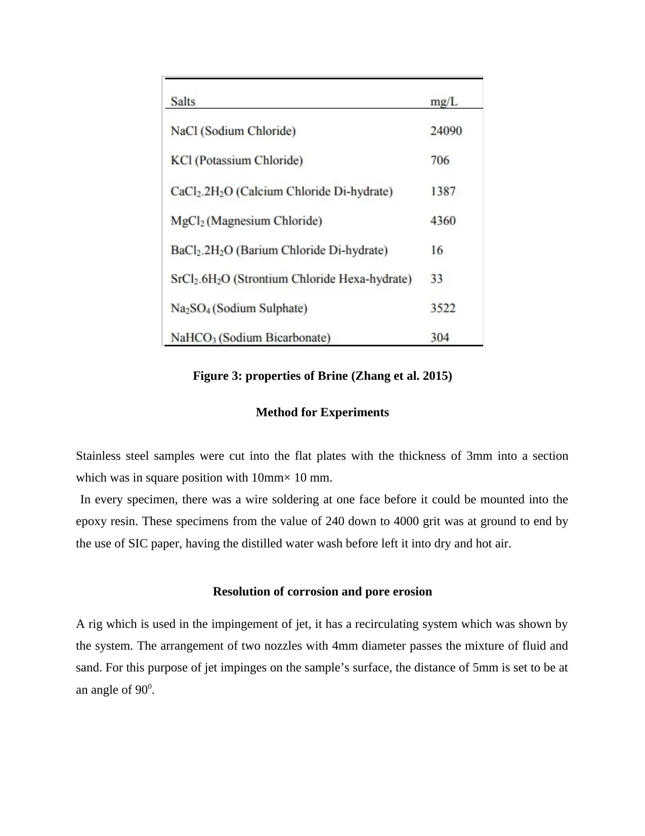
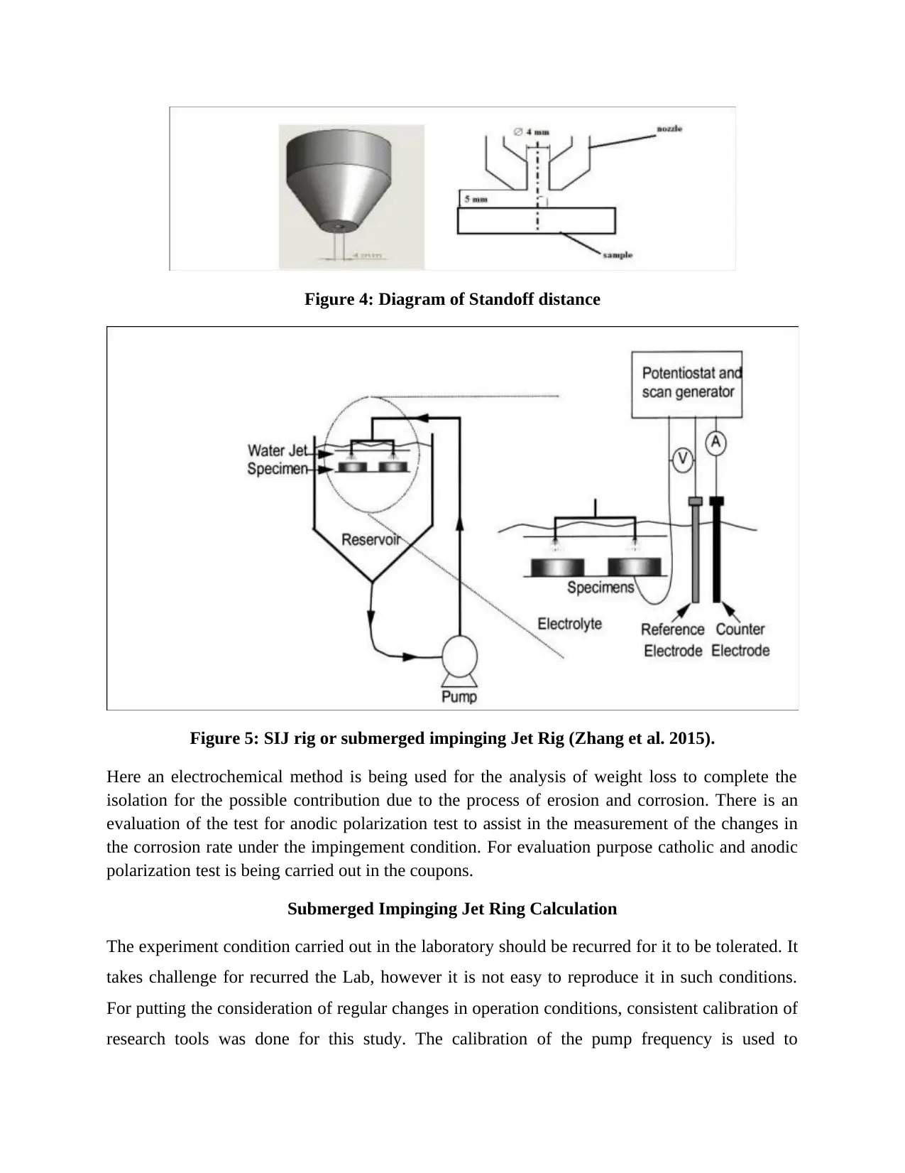
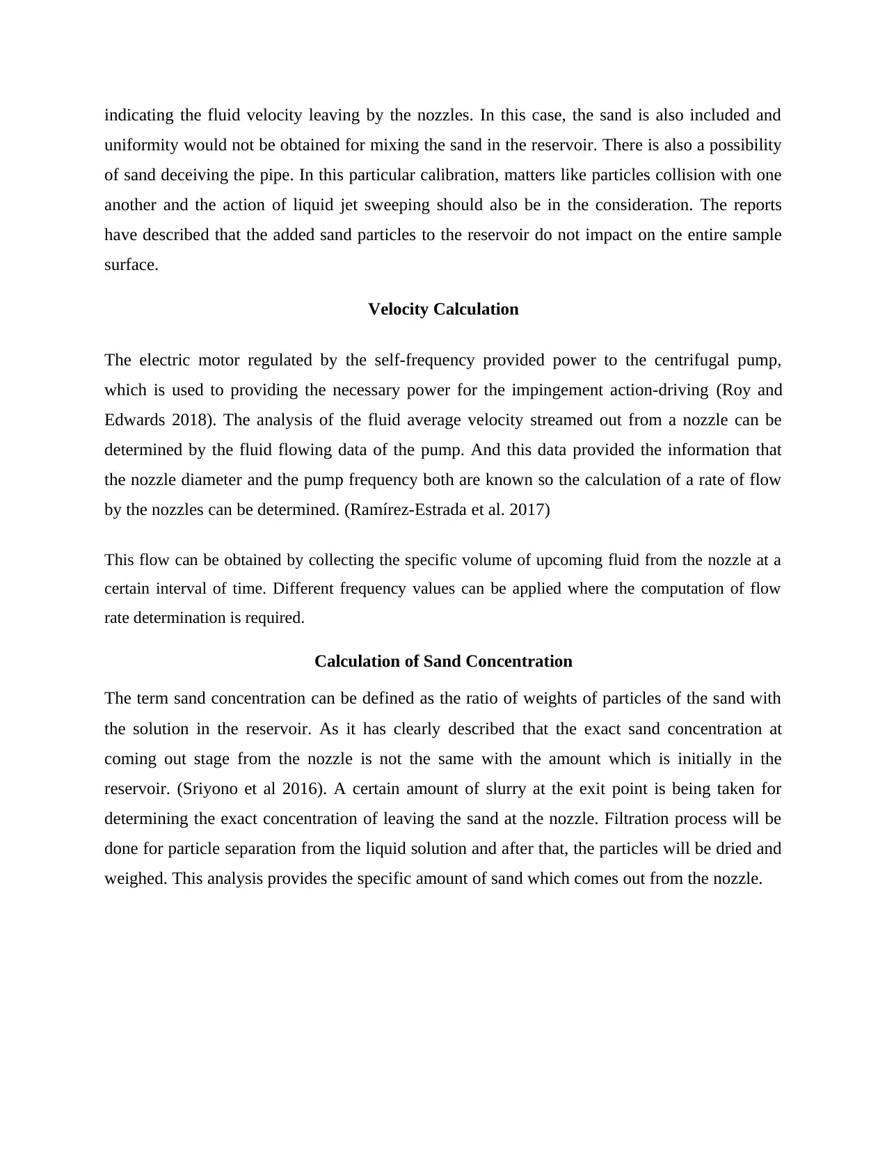
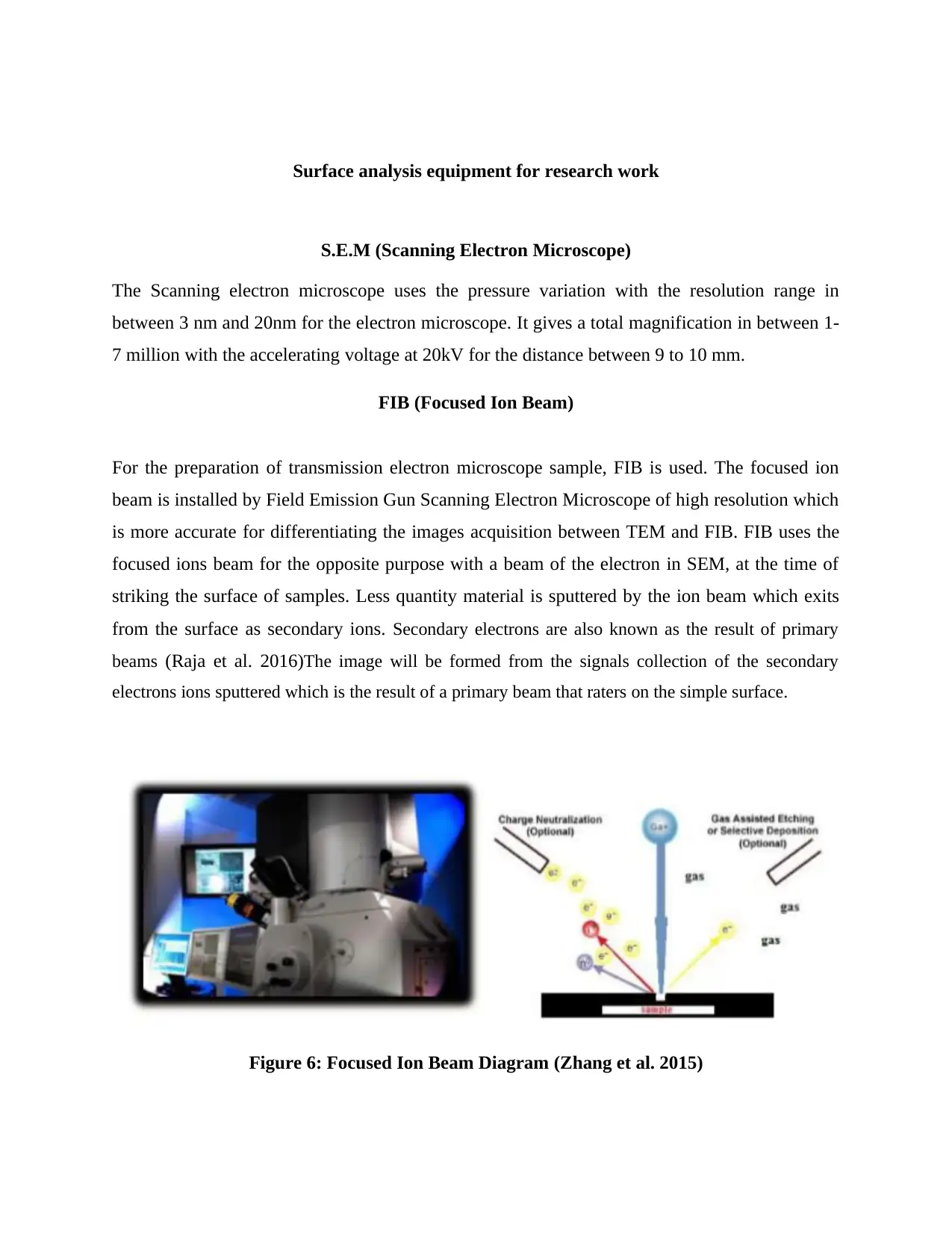
This report investigates the localized corrosion of additive manufactured stainless steels under simulated pipeline mechanical corrosion and erosion conditions, focusing on materials used in oil and gas pipelines. It details the research objective, which is to simulate and understand this corrosion, and provides a comprehensive literature review on stainless steel properties and corrosion mechanisms. The methodology includes experimental methods using a submerged impinging jet rig to simulate pipeline conditions, along with calculations for velocity and sand concentration. Surface analysis techniques such as SEM, FIB, and TEM are employed to examine the corroded surfaces. The report outlines expected results, compares them with actual outcomes, discusses the limitations and advantages of the techniques used, and concludes with a summary of the findings. The report also includes detailed information about the experimental setup, materials used, and the specific methods for corrosion testing, including potentiostatic holds, cyclic potentio-dynamic, and double loop electrochemical potentio-kinetic reactivation analysis. The research aims to enhance understanding of corrosion behavior and improve the durability of components in corrosive environments.
Document Page
PROJECT TITLE
SIMULATING AND UNDERSTANDING LOCALISED CORROSION OF ADDITIVE
MANUFACTURED STAINLESS STEELS UNDER SIMULATED PIPELINE
MECHANICAL CORROSION AND EROSION CONDITIONS.
tabler-icon-diamond-filled.svg

Paraphrase This Document

Need a fresh take? Get an instant paraphrase of this document with our AI Paraphraser
Document Page
Table of Contents
Introduction 3
Research objective 4
Literature review 5
Testing of Corrosion 6
Work Methodology 6
Methods for experiment 9
Resolution of corrosion and pore erosion 9
Submerged Impinging Jet Ring Calculation 10
Velocity Calculation 11
Calculation of Sand concentration 11
Surface analysis equipment for research work 12
S.E.M (Scanning Electron Microscope) 12
F.I.B (Focused Ion Beam) 12
T.E.M(Transmission Electron Microscopy) 13
Expected Results 13
Actual Outcomes and their comparison with the expected result 15
Technique Limitations 18
Advantages 18
Conclusion 19
References 20
Document Page
Introduction
The term, Localized corrosion describes the selective metal removal by corrosion at little areas on the
corrosive environment of metal, mostly in the form of liquid. When the small local sites are attacked
at a higher rate than the original surface, local corrosion occurs at that time.
Most of the time, it occurs when the corrosion works with the other chemical reaction such as the
erosion, fatigue and stress. The localized corrosion can cause more damage than any of the individual
destructive technique. These techniques can be defined as wastage, stress corrosion cracking, heat
exchanger tube denting etc.
Additive manufacturing is being used widely in past timing due to its ease in the production of
complex parts which are used in several applications such as aerospace and petrochemicals.
(Milewski, 2017, p. 159).
Along with the literature of additive manufacturing is also being described in this report for the
description of additive manufactured alloys. The report describes the localized corrosion of stainless
steel manufacturing by additive manufacturing technique under the simulated pipeline mechanical
corrosion and erosion condition.
Corrosion is an attack by environmental component such as land, water etc. which turns toxic. And
the natural potential hazards which are concerned with the transportation facility in the field of gas
and oil production. Almost any of the concern environments can produce the corrosion effect, which
comes under the number of complex condition for oil and gas production, processing purpose and the
pipeline system. (Popoola et al., 2013)
This process contains the three major elements such as the cathode, anode and the electrolyte. In this
construction, anode denotes the site of corroding metal and electrolyte shows as the corrosive
medium which enables the electrons transfer in the direction of the anode to cathode. And electrons
work as the electric conductor which cannot be consumed in the process of corrosion. Oil and natural
gases a carry the inherently corrosive products which are having the high impurity in it. The
examples of this corrosive media with high range are carbon dioxide, free water and hydrogen sulfide
etc. (Popoola et al., 2013)
Document Page
Research Objective
The objective of the report is to simulate and understand the localized corrosion of stainless steel
by additive manufacturing under the simulated pipeline mechanical corrosion and erosion
condition. There are several objectives which are useful to assist in achieving the main aim of the
research project which includes, the localized corrosion findings, illustration of additive
manufacturing concepts and stainless steel properties.
The main research objective of this project is to compare the expected result for the corrosion
process at various samples with the actual outcome which is being got by the experiment in such
samples.
tabler-icon-diamond-filled.svg

Paraphrase This Document

Need a fresh take? Get an instant paraphrase of this document with our AI Paraphraser
Document Page
Literature Review
The stainless steel is having the feature of high-level resistance of corrosion which is due to the
presence of alloyed chromium. This helps in the formation of chromium oxide which is based on
the passive film on the metal surfaces (Davis, 2018, p. 82). The extra elements added in stainless
steel such as copper, selenium carbon can modify the corrosion resistance which increases the
strength, ductility and the machinability.
The exploration of more extensive perspective is being done which gives the review of different
hypotheses regarding the localized corrosion in substance stainless steel. This is the initial
research which must be filled by elaborating the design based writing audit so that the
researchers should have concentrated on surveying the explanation of corrosion of metal. The
result of added substance fabrication on stainless steel corrosion is the same as the accessed in
this research exploration for controlling the examination hole and erosion controlling procedure
execution.
The various systems which are intended to gauge in corrosion level of stainless steel will
diminish the research hole between the looks quantity into led in worry of the selected subject.
It is shown that the restriction of setting erosion was upgraded by the particle implantation as
none of the exam performed on the surface. When the surface was at a relaxed position, the
improvement in localized erosion gets achieved after particle implantation.
In today, several industries have lost good amount of money for the observation purpose in
corrosion outcomes. In some reports, it describes that many oil companies had their pipeline
ruptured, by which the pollution in environment increases. And many of the companies are doing
research on it to overcome this issue. (Popoola et al., 2013)
Document Page
Testing of Corrosion
Polished stainless steel corrosion can be investigated by the several methods such as potentio-
static holds, cyclic potentio-dynamic and the double loop electrochemical potentio-kinetic
reactivation with the post- and premortem analysis.
Work Methodology
The motive of this project work is to enhance the idea and knowledge on the topic of corrosion
and erosion of stainless steel. There are various methods, which are being implemented to
achieve the aim, have been set for further investigation. There was a determination of the
breakdown potential for at least six alloys, in the phenomena of static corrosion condition. There
are two particular alloys which are being chosen for the content variation of the manganese and
the close pitting resistance which is equal to the stated number.
Document Page
Figure 1: Diagram of the SLM Machine (Zhang et al. 2017)
There was a consideration of at least four alloys under the flow-induced corrosion condition. The
erosion and corrosion behaviour of these alloys were studied in SIJ for the condition of the
saturated carbon dioxide along with air having the velocity of 15m/s. so the results were then
produced in the FEA simulation analysis which is shown in the figure later.
The inner diameter of the piping got the stress from the resistant material corrosion barrier and
the compressive residual for the prevention of further cracking. An analysis is being represented
for the pre-emptive full structural WOL in corresponded with the assumption of flow depth as
75% of the thickness of the wall with the full circumstances at 3600, is known as the crack
growth. (Kang & Kupca 2011).
From the selected alloy samples for the stainless steel, UNSS30403 and UNS32101 have
produced from the SLM 125HL machine which equipment name is 200w YLR- Fuser-Laser
(λ=1070 nm). And the location of this machine is the first floor of CADET. The proposed sample
specimen had dimensions of 10x10x10 mm3 for the experiment purpose. There was the use of
high velocity having the value of 24m/s for the study of erosion-corrosion behaviour of the
samples under the sodium chloride saturated solution known as brine. (Wu et al. 2015)
The selection of the four alloys such as UNSS30403, UNSS32304, UNS31603 and 316LSS. Was
very important for the consideration and representation of at least and every class.
tabler-icon-diamond-filled.svg

Paraphrase This Document

Need a fresh take? Get an instant paraphrase of this document with our AI Paraphraser
Document Page
Figure 2: Used Steel Sample (Zhang et al. 2017)
Concentrated Sodium Chloride experiment:
This is also known as brine. Two samples of the brine are being used in this research work of
3.5% of the NaCl solution which was aerated to be used. And also the oilfield brine saturated
with the large quantity of carbon dioxide gas which is used.
Document Page
Figure 3: properties of Brine (Zhang et al. 2015)
Method for Experiments
Stainless steel samples were cut into the flat plates with the thickness of 3mm into a section
which was in square position with 10mm× 10 mm.
In every specimen, there was a wire soldering at one face before it could be mounted into the
epoxy resin. These specimens from the value of 240 down to 4000 grit was at ground to end by
the use of SIC paper, having the distilled water wash before left it into dry and hot air.
Resolution of corrosion and pore erosion
A rig which is used in the impingement of jet, it has a recirculating system which was shown by
the system. The arrangement of two nozzles with 4mm diameter passes the mixture of fluid and
sand. For this purpose of jet impinges on the sample’s surface, the distance of 5mm is set to be at
an angle of 900.
Document Page
Figure 4: Diagram of Standoff distance
Figure 5: SIJ rig or submerged impinging Jet Rig (Zhang et al. 2015).
Here an electrochemical method is being used for the analysis of weight loss to complete the
isolation for the possible contribution due to the process of erosion and corrosion. There is an
evaluation of the test for anodic polarization test to assist in the measurement of the changes in
the corrosion rate under the impingement condition. For evaluation purpose catholic and anodic
polarization test is being carried out in the coupons.
Submerged Impinging Jet Ring Calculation
The experiment condition carried out in the laboratory should be recurred for it to be tolerated. It
takes challenge for recurred the Lab, however it is not easy to reproduce it in such conditions.
For putting the consideration of regular changes in operation conditions, consistent calibration of
research tools was done for this study. The calibration of the pump frequency is used to
tabler-icon-diamond-filled.svg

Paraphrase This Document

Need a fresh take? Get an instant paraphrase of this document with our AI Paraphraser
Document Page
indicating the fluid velocity leaving by the nozzles. In this case, the sand is also included and
uniformity would not be obtained for mixing the sand in the reservoir. There is also a possibility
of sand deceiving the pipe. In this particular calibration, matters like particles collision with one
another and the action of liquid jet sweeping should also be in the consideration. The reports
have described that the added sand particles to the reservoir do not impact on the entire sample
surface.
Velocity Calculation
The electric motor regulated by the self-frequency provided power to the centrifugal pump,
which is used to providing the necessary power for the impingement action-driving (Roy and
Edwards 2018). The analysis of the fluid average velocity streamed out from a nozzle can be
determined by the fluid flowing data of the pump. And this data provided the information that
the nozzle diameter and the pump frequency both are known so the calculation of a rate of flow
by the nozzles can be determined. (Ramírez-Estrada et al. 2017)
This flow can be obtained by collecting the specific volume of upcoming fluid from the nozzle at a
certain interval of time. Different frequency values can be applied where the computation of flow
rate determination is required.
Calculation of Sand Concentration
The term sand concentration can be defined as the ratio of weights of particles of the sand with
the solution in the reservoir. As it has clearly described that the exact sand concentration at
coming out stage from the nozzle is not the same with the amount which is initially in the
reservoir. (Sriyono et al 2016). A certain amount of slurry at the exit point is being taken for
determining the exact concentration of leaving the sand at the nozzle. Filtration process will be
done for particle separation from the liquid solution and after that, the particles will be dried and
weighed. This analysis provides the specific amount of sand which comes out from the nozzle.
Document Page
Surface analysis equipment for research work
S.E.M (Scanning Electron Microscope)
The Scanning electron microscope uses the pressure variation with the resolution range in
between 3 nm and 20nm for the electron microscope. It gives a total magnification in between 1-
7 million with the accelerating voltage at 20kV for the distance between 9 to 10 mm.
FIB (Focused Ion Beam)
For the preparation of transmission electron microscope sample, FIB is used. The focused ion
beam is installed by Field Emission Gun Scanning Electron Microscope of high resolution which
is more accurate for differentiating the images acquisition between TEM and FIB. FIB uses the
focused ions beam for the opposite purpose with a beam of the electron in SEM, at the time of
striking the surface of samples. Less quantity material is sputtered by the ion beam which exits
from the surface as secondary ions. Secondary electrons are also known as the result of primary
beams (Raja et al. 2016)The image will be formed from the signals collection of the secondary
electrons ions sputtered which is the result of a primary beam that raters on the simple surface.
Figure 6: Focused Ion Beam Diagram (Zhang et al. 2015)
chevron_up_icon
1 out of 21
circle_padding
hide_on_mobile
zoom_out_icon
[object Object]