Application of Counters and Timers in Electrical Engineering Systems

Verified

Added on  2022/08/11

|5
|660
|31
Homework Assignment
AI Summary
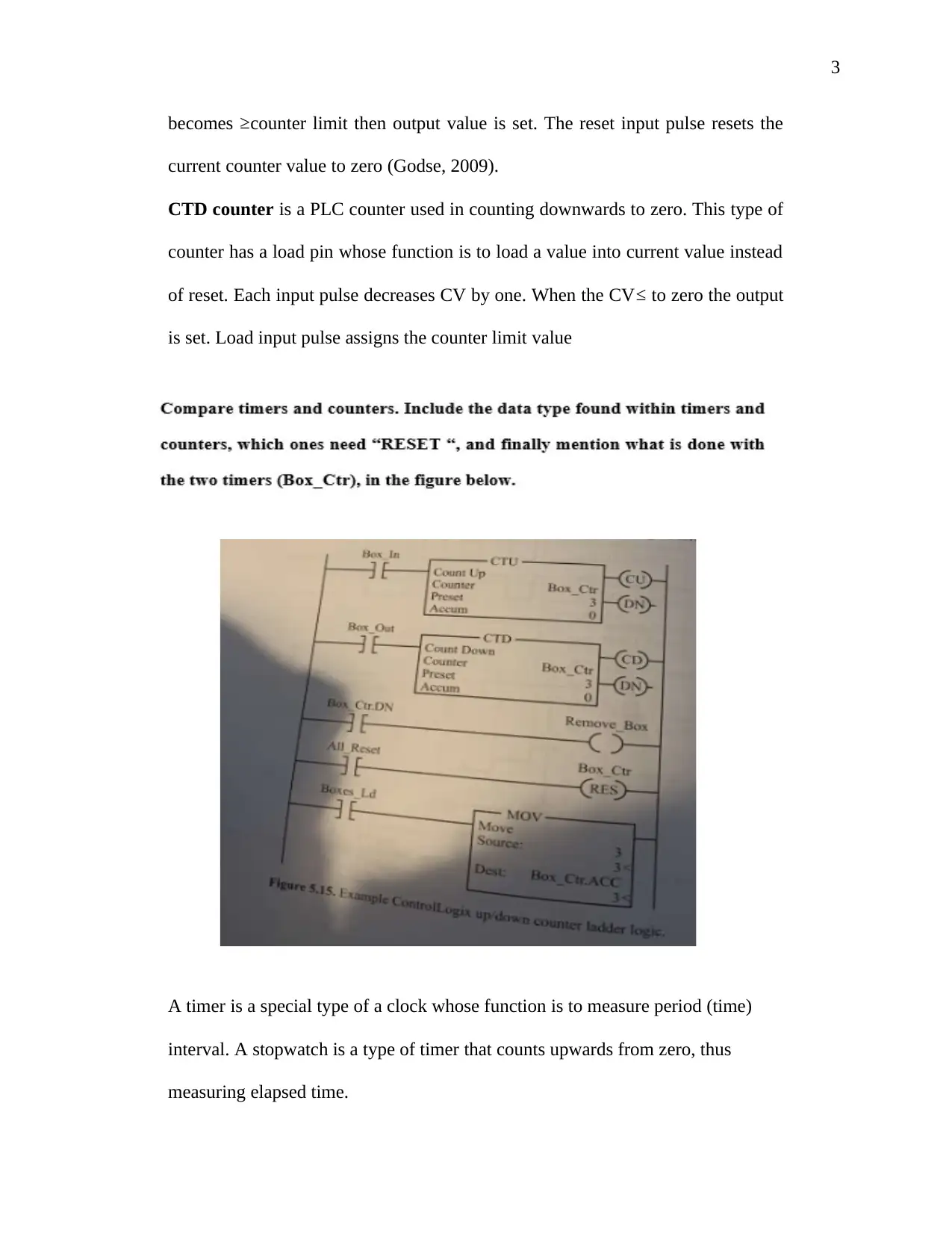
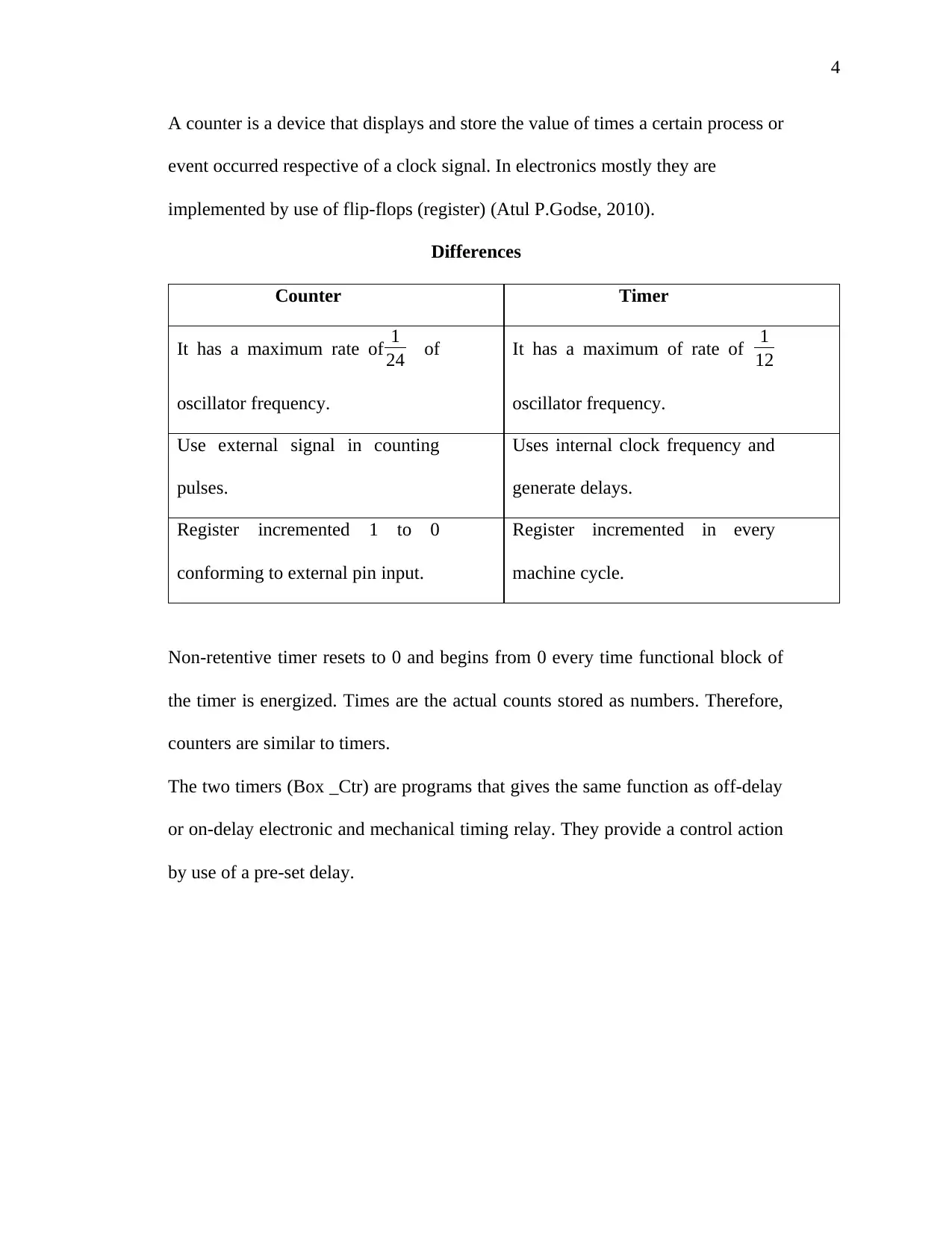
This assignment provides an overview of counters and timers, focusing on their application in electrical engineering and control systems. It begins by explaining the functions of TON (Timer On), TOF (Timer Off), and RTO (Retentive Timer On) timers, detailing their behavior and operational differences. The assignment then describes PLC counters, including CTU (Counter Up) and CTD (Counter Down), highlighting their roles in counting and control applications. It differentiates between timers and counters, emphasizing their respective uses in measuring time intervals and counting events, as well as the difference between internal clock frequency and external signal in counting pulses. The assignment also notes the similarities between timers and counters, such as the use of pre-set delays in control actions. References to relevant literature, including works by Atul P. Godse and S. Money, are included to support the information provided. This document is designed to enhance understanding of these fundamental concepts in electrical engineering.
Document Page
1
Counters and Timers
Name
Institutional Affiliation
tabler-icon-diamond-filled.svg

Paraphrase This Document

Need a fresh take? Get an instant paraphrase of this document with our AI Paraphraser
Document Page
2
Counters and Timers.
TON timer is a timer used in delaying turning an output ON. The out bit of the
timer turns ON after the timer has completed running. When pre-set value is
loaded into existing value the 1st time the timer is scanning the program. When the
timer’s input conditions rises, the timer starts to decrease and when the existing
value reaches zero, while input conditions is ON, the out bit turns ON. When
input conditions falls, preset value is loaded to current value.
TOF timer is a timer used in delaying an output OFF. The out bit of the timer
turns OFF after the timer has completed running. When the timers input
conditions increases, the out bit of the timer turns ON and loads the pre-set value
to current value. Falling in the input condition of the timer, the timer starts to
decrease, out bit of the timer remains ON as the timer is running and when
current value equals TO zero ,bit out of the timer turns OFF. If input conditions
of the timer increases while the timer is decreasing, out bit of the timer remains
ON and time stops operating (Money, 2014).
RTO timer is a timer that counts interval of time when the instruction feed is true
and holds the accumulated value. Incase power cycles arises or the instruction
becomes false, the program starts to count the base time interval and the
operational conditions becomes true.
CTU counter is a PLC counter that is used in counting upwards. Individual pulse
on the count input increases the CV of the counter by one. In case the CV
Document Page
3
becomes counter limit then output value is set. The reset input pulse resets the
current counter value to zero (Godse, 2009).
CTD counter is a PLC counter used in counting downwards to zero. This type of
counter has a load pin whose function is to load a value into current value instead
of reset. Each input pulse decreases CV by one. When the CV to zero the output
is set. Load input pulse assigns the counter limit value
A timer is a special type of a clock whose function is to measure period (time)
interval. A stopwatch is a type of timer that counts upwards from zero, thus
measuring elapsed time.
Document Page
4
A counter is a device that displays and store the value of times a certain process or
event occurred respective of a clock signal. In electronics mostly they are
implemented by use of flip-flops (register) (Atul P.Godse, 2010).
Differences
Counter Timer
It has a maximum rate of 1
24 of
oscillator frequency.
It has a maximum of rate of 1
12
oscillator frequency.
Use external signal in counting
pulses.
Uses internal clock frequency and
generate delays.
Register incremented 1 to 0
conforming to external pin input.
Register incremented in every
machine cycle.
Non-retentive timer resets to 0 and begins from 0 every time functional block of
the timer is energized. Times are the actual counts stored as numbers. Therefore,
counters are similar to timers.
The two timers (Box _Ctr) are programs that gives the same function as off-delay
or on-delay electronic and mechanical timing relay. They provide a control action
by use of a pre-set delay.
tabler-icon-diamond-filled.svg

Paraphrase This Document

Need a fresh take? Get an instant paraphrase of this document with our AI Paraphraser
Document Page
5
References
Atul P.Godse, D. A. (2010). Microprocessor and Microcontroller . London: Technical
Publication.
Godse, D. A. (2009). Microcontrollers. London: Technical Publication.
Money, S. (2014). Newnes Microprocessor Pocket Book. New York: Elsevier.
chevron_up_icon
1 out of 5
circle_padding
hide_on_mobile
zoom_out_icon
[object Object]