CPCCBC4011B - Structural Principles in Portal Frame Construction
VerifiedAdded on 2023/06/11
|32
|5134
|59
Report
AI Summary
This report provides a comprehensive overview of portal frame construction, focusing on its structural principles and application in low-rise commercial buildings. It covers essential elements such as the footing system, structural system (including fly bracing, columns, rafters, end wall columns, girts, purlins, and bracing), floor system (surface treatment and joints), wall systems, roof system (cladding and flashing), and service systems (electricity, telecommunications, sewage, water, and fire protection). The report includes observations and images from an industrial unit to illustrate key concepts and practical applications of portal frame construction techniques. The document is contributed by a student and available on Desklib, where students can find similar solved assignments and past papers.
Portal frame construction 1
PORTAL FRAME CONSTRUCTION
By Name
Course
Instructor
Institution
Location
Date
PORTAL FRAME CONSTRUCTION
By Name
Course
Instructor
Institution
Location
Date
Paraphrase This Document
Need a fresh take? Get an instant paraphrase of this document with our AI Paraphraser

Portal frame construction 2
Table of Contents
1.0 Introduction.........................................................................................................................................3
2.0 Background.........................................................................................................................................4
3.0 Footing system....................................................................................................................................5
4.0 Structural system................................................................................................................................7
4.1 Fly bracing..........................................................................................................................................8
4.2 Column and rafter...............................................................................................................................9
4.3 Endwall column................................................................................................................................11
4.4 Girts and purlins...............................................................................................................................12
4.5 Bracing..............................................................................................................................................13
5.0 Floor system......................................................................................................................................13
5.1 Surface treatment..............................................................................................................................14
5.2 Floor joints.......................................................................................................................................16
5.21 Contraction Joints...........................................................................................................................16
5.22Construction joints..........................................................................................................................16
5.23 Isolation joints................................................................................................................................17
5.24 Expansion joint...............................................................................................................................18
6.0 Wall sytems.......................................................................................................................................18
6.1 Connctions and fixtures...................................................................................................................19
7.0 Roof stsem for portal frame systems..............................................................................................19
7.1 Roof cladding....................................................................................................................................20
7.2 Gutter and flashing details...............................................................................................................21
8.0 Service systems.................................................................................................................................22
8.1 Electricity and telecommunications...............................................................................................22
8.2 Sewage and water.............................................................................................................................22
8.3 Fire protection...................................................................................................................................23
9.0 CONCLUSION................................................................................................................................24
10. 0 Reference.......................................................................................................................................26
Portal frame construction 3
PORTAL FRAME CONSTRUCTION
1.0 Introduction
Portal frame construction refers to the technique of designing and constructing structures,
whereby two-dimensional rigid frames with basic characteristics of the rigid joint are between
the beam and the column are utilized (Hiriyur,2010). The main aim of using this method of
designing and construction is to reduce the bending moments in the beam in order to allow the
frame to act as one structural unit. With that, the size of the structural element can be reduced or
at the same time, and the span can be increased for the same size of the structural elements. Due
to that, the portal frames are considered to be very efficient and reliable construction method to
be used for the buildings with long span.
Portal frames are generally being used in the low-rise structures, which are comprised of beams,
columns or pitched rafters that are connected by the moment resisting connections. The
resistance to vertical and lateral actions is offered by a suitable haunch, or the deepening of the
rafter sections This type of continuous frame structure is usually stable in its plane, and it offers
clear span which is not obstructed by the bracing. In most cases, the portal frame construction is
used in the construction of single-level structures, and it is usually seen in the construction of
factories, warehouses, barns and other areas where large open spaces are needed at low cost and
a pitched roof is also accepted.
A portal frame structure usually comprises a series of transverse frames which are braced
longitudinally. The primary steelwork is made up of rafters and columns, which makes the form
portal frames and bracing. The gable frame can be either a portal frame or a braced arrangement
of columns and rafters.
⊘ This is a preview!⊘
Do you want full access?
Subscribe today to unlock all pages.
Trusted by 1+ million students worldwide
Portal frame construction 4
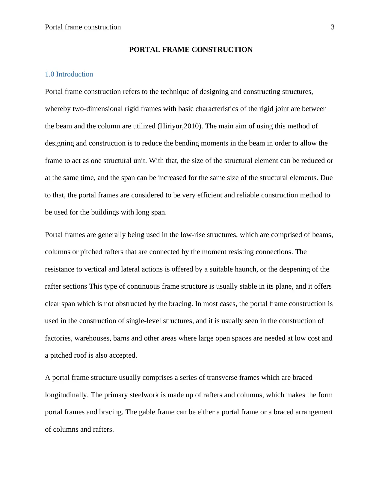
The light gauge secondary steelwork is made up of the side rails which are used for the walls and
the purlins that are used for the roof. The secondary steelwork offers support to the building
envelope, but it also plays a very significant role in restraining the primary steelwork. The wall
cladding and the roof separates the building envelope from the external environment as well as
offering acoustic and thermal insulation. The function of cladding is to transfer the loads to the
secondary steelwork and at the same time to restrain the flange of rails or purlins to which it is
attached (Paolacci and Giannini 2012). The figure below shows the anatomy of a typical portal
frame.
Fig 1: A cross-section showing portal frame and its restraints
Paraphrase This Document
Need a fresh take? Get an instant paraphrase of this document with our AI Paraphraser
Portal frame construction 5
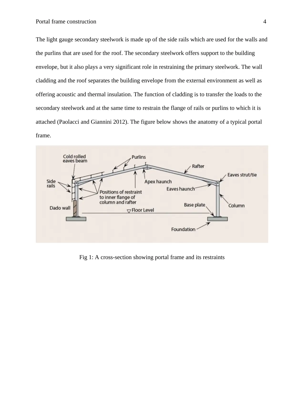
Fig 2: Principal Components of a portal framed structure.
The key focus of this paper provides a discussion of the technical aspects of the portal frame
construction. The area which is analyzed in this paper include; structural system, footing system,
wall system, floor system, roof system, and services. The information which is contained in this
paper is based on the deep investigation of Industrial unit 6D,1-3 Endeavour road. The
photographs are included in the discussion part to over clarification. The areas which were
mentioned in the assignment brief have been covered for simplicity.
2.0 Background
The industrial unit is located within the center of the Sutherland Shire’s Industrial Precinct. It has
a total area of approximately 850 m2. The ground floor is typically a warehouse of
Portal frame construction 6
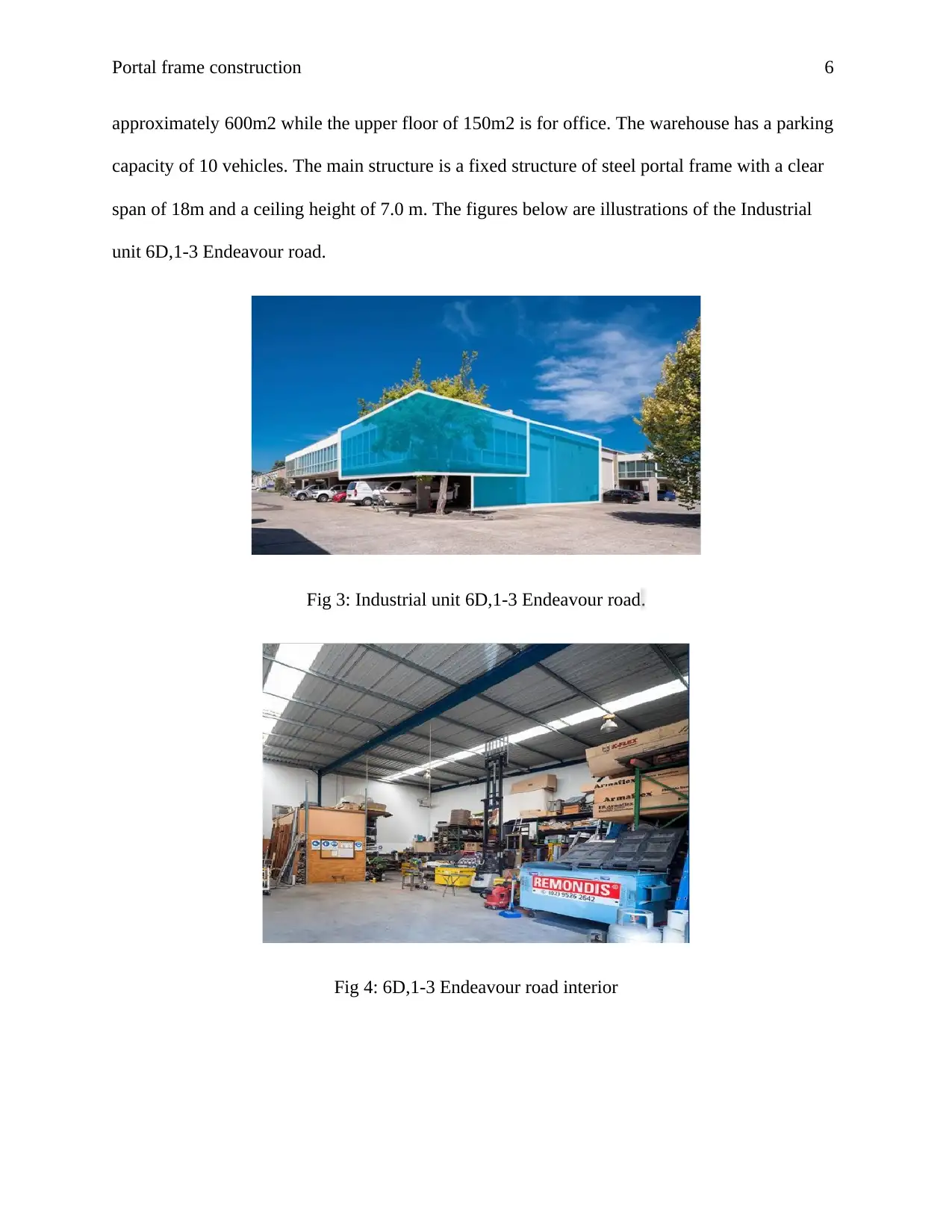
approximately 600m2 while the upper floor of 150m2 is for office. The warehouse has a parking
capacity of 10 vehicles. The main structure is a fixed structure of steel portal frame with a clear
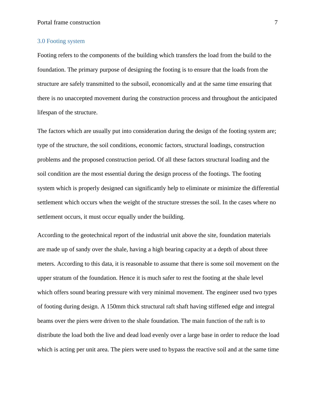
span of 18m and a ceiling height of 7.0 m. The figures below are illustrations of the Industrial
unit 6D,1-3 Endeavour road.
Fig 3: Industrial unit 6D,1-3 Endeavour road.
Fig 4: 6D,1-3 Endeavour road interior
approximately 600m2 while the upper floor of 150m2 is for office. The warehouse has a parking
capacity of 10 vehicles. The main structure is a fixed structure of steel portal frame with a clear
span of 18m and a ceiling height of 7.0 m. The figures below are illustrations of the Industrial
unit 6D,1-3 Endeavour road.
Fig 3: Industrial unit 6D,1-3 Endeavour road.
Fig 4: 6D,1-3 Endeavour road interior
⊘ This is a preview!⊘
Do you want full access?
Subscribe today to unlock all pages.
Trusted by 1+ million students worldwide
Portal frame construction 7
3.0 Footing system
Footing refers to the components of the building which transfers the load from the build to the
foundation. The primary purpose of designing the footing is to ensure that the loads from the
structure are safely transmitted to the subsoil, economically and at the same time ensuring that
there is no unaccepted movement during the construction process and throughout the anticipated
lifespan of the structure.
The factors which are usually put into consideration during the design of the footing system are;
type of the structure, the soil conditions, economic factors, structural loadings, construction
problems and the proposed construction period. Of all these factors structural loading and the
soil condition are the most essential during the design process of the footings. The footing
system which is properly designed can significantly help to eliminate or minimize the differential
settlement which occurs when the weight of the structure stresses the soil. In the cases where no
settlement occurs, it must occur equally under the building.
According to the geotechnical report of the industrial unit above the site, foundation materials
are made up of sandy over the shale, having a high bearing capacity at a depth of about three
meters. According to this data, it is reasonable to assume that there is some soil movement on the
upper stratum of the foundation. Hence it is much safer to rest the footing at the shale level
which offers sound bearing pressure with very minimal movement. The engineer used two types
of footing during design. A 150mm thick structural raft shaft having stiffened edge and integral
beams over the piers were driven to the shale foundation. The main function of the raft is to
distribute the load both the live and dead load evenly over a large base in order to reduce the load
which is acting per unit area. The piers were used to bypass the reactive soil and at the same time
Paraphrase This Document
Need a fresh take? Get an instant paraphrase of this document with our AI Paraphraser
Portal frame construction 8
transfer the superstructure load at the edge beam to the lower level of subsoil where suitable
ABP exist. The figure below shows the arrangement of this structural members.
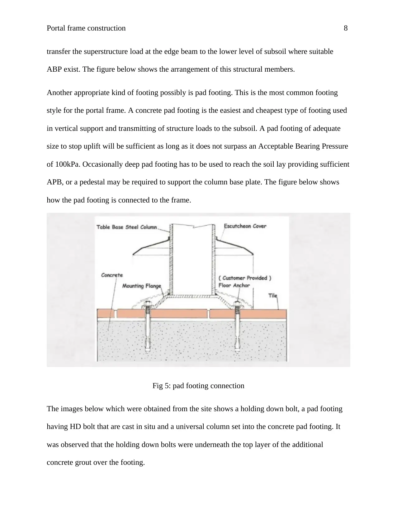
Another appropriate kind of footing possibly is pad footing. This is the most common footing
style for the portal frame. A concrete pad footing is the easiest and cheapest type of footing used
in vertical support and transmitting of structure loads to the subsoil. A pad footing of adequate
size to stop uplift will be sufficient as long as it does not surpass an Acceptable Bearing Pressure
of 100kPa. Occasionally deep pad footing has to be used to reach the soil lay providing sufficient
APB, or a pedestal may be required to support the column base plate. The figure below shows
how the pad footing is connected to the frame.
Fig 5: pad footing connection
The images below which were obtained from the site shows a holding down bolt, a pad footing
having HD bolt that are cast in situ and a universal column set into the concrete pad footing. It
was observed that the holding down bolts were underneath the top layer of the additional
concrete grout over the footing.
transfer the superstructure load at the edge beam to the lower level of subsoil where suitable
ABP exist. The figure below shows the arrangement of this structural members.
Another appropriate kind of footing possibly is pad footing. This is the most common footing
style for the portal frame. A concrete pad footing is the easiest and cheapest type of footing used
in vertical support and transmitting of structure loads to the subsoil. A pad footing of adequate
size to stop uplift will be sufficient as long as it does not surpass an Acceptable Bearing Pressure
of 100kPa. Occasionally deep pad footing has to be used to reach the soil lay providing sufficient
APB, or a pedestal may be required to support the column base plate. The figure below shows
how the pad footing is connected to the frame.
Fig 5: pad footing connection
The images below which were obtained from the site shows a holding down bolt, a pad footing
having HD bolt that are cast in situ and a universal column set into the concrete pad footing. It
was observed that the holding down bolts were underneath the top layer of the additional
concrete grout over the footing.
Portal frame construction 9
Fig 6: hold down bolts
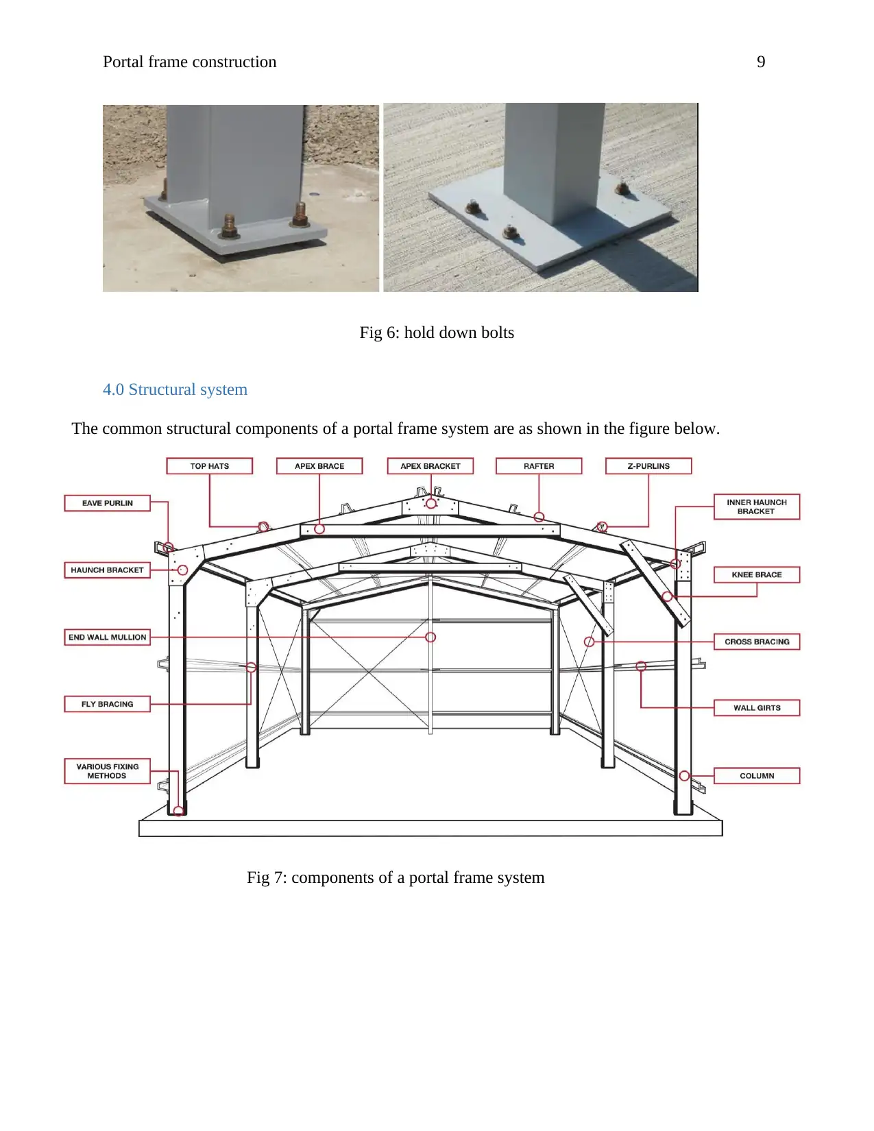
4.0 Structural system
The common structural components of a portal frame system are as shown in the figure below.
Fig 7: components of a portal frame system
Fig 6: hold down bolts
4.0 Structural system
The common structural components of a portal frame system are as shown in the figure below.
Fig 7: components of a portal frame system
⊘ This is a preview!⊘
Do you want full access?
Subscribe today to unlock all pages.
Trusted by 1+ million students worldwide
Portal frame construction
10
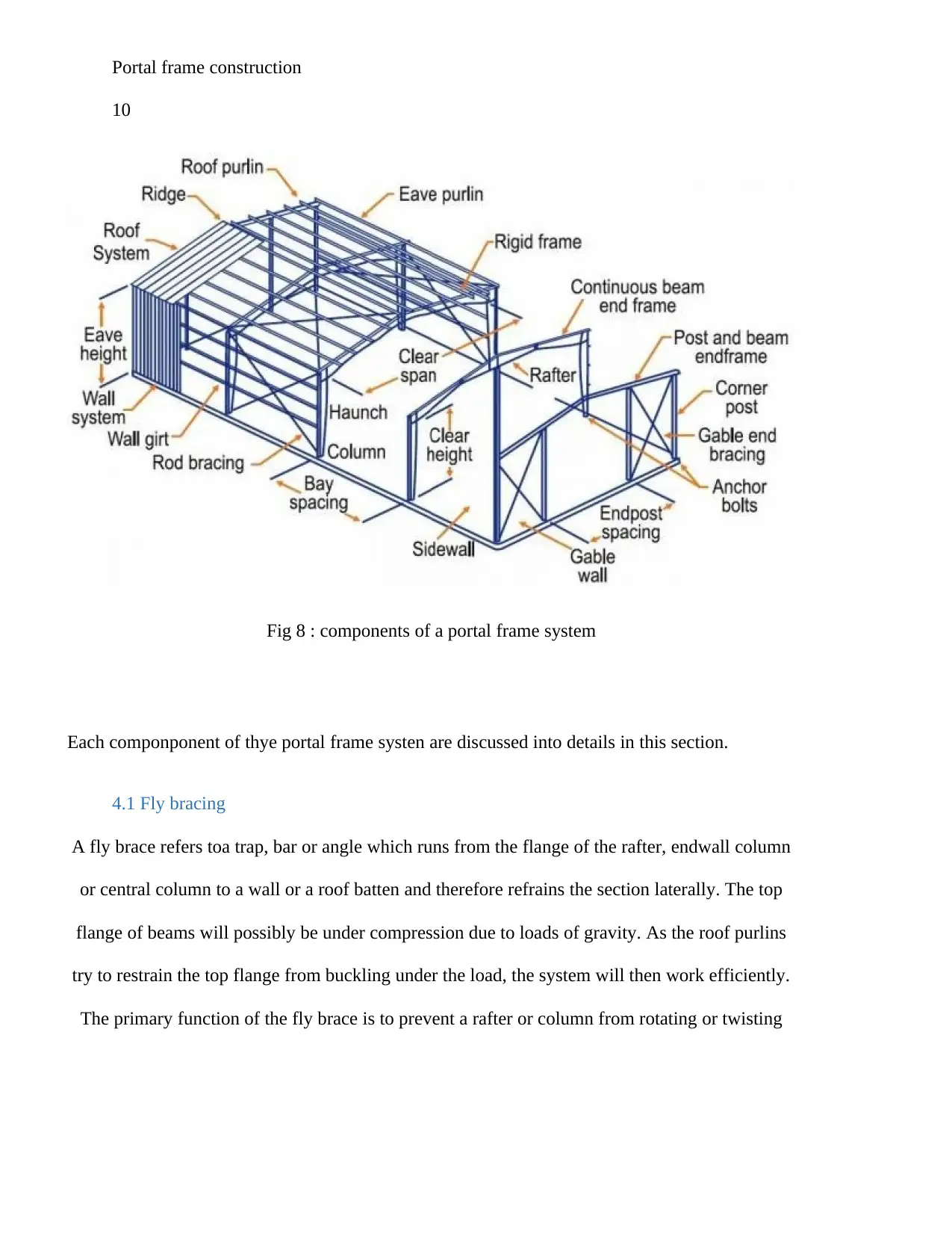
Fig 8 : components of a portal frame system
Each componponent of thye portal frame systen are discussed into details in this section.
4.1 Fly bracing
A fly brace refers toa trap, bar or angle which runs from the flange of the rafter, endwall column
or central column to a wall or a roof batten and therefore refrains the section laterally. The top
flange of beams will possibly be under compression due to loads of gravity. As the roof purlins
try to restrain the top flange from buckling under the load, the system will then work efficiently.
The primary function of the fly brace is to prevent a rafter or column from rotating or twisting
10
Fig 8 : components of a portal frame system
Each componponent of thye portal frame systen are discussed into details in this section.
4.1 Fly bracing
A fly brace refers toa trap, bar or angle which runs from the flange of the rafter, endwall column
or central column to a wall or a roof batten and therefore refrains the section laterally. The top
flange of beams will possibly be under compression due to loads of gravity. As the roof purlins
try to restrain the top flange from buckling under the load, the system will then work efficiently.
The primary function of the fly brace is to prevent a rafter or column from rotating or twisting
Paraphrase This Document
Need a fresh take? Get an instant paraphrase of this document with our AI Paraphraser
Portal frame construction
11
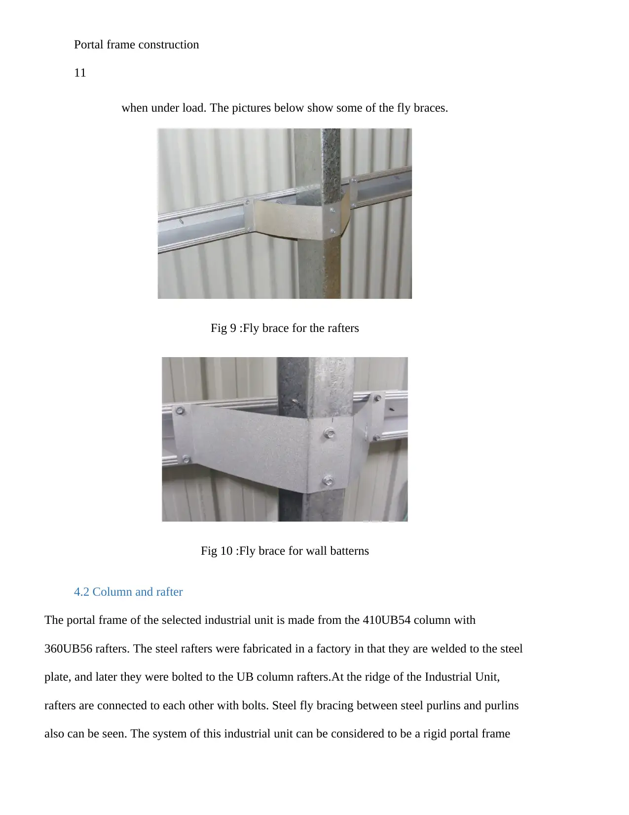
when under load. The pictures below show some of the fly braces.
Fig 9 :Fly brace for the rafters
Fig 10 :Fly brace for wall batterns
4.2 Column and rafter
The portal frame of the selected industrial unit is made from the 410UB54 column with
360UB56 rafters. The steel rafters were fabricated in a factory in that they are welded to the steel
plate, and later they were bolted to the UB column rafters.At the ridge of the Industrial Unit,
rafters are connected to each other with bolts. Steel fly bracing between steel purlins and purlins
also can be seen. The system of this industrial unit can be considered to be a rigid portal frame
11
when under load. The pictures below show some of the fly braces.
Fig 9 :Fly brace for the rafters
Fig 10 :Fly brace for wall batterns
4.2 Column and rafter
The portal frame of the selected industrial unit is made from the 410UB54 column with
360UB56 rafters. The steel rafters were fabricated in a factory in that they are welded to the steel
plate, and later they were bolted to the UB column rafters.At the ridge of the Industrial Unit,
rafters are connected to each other with bolts. Steel fly bracing between steel purlins and purlins
also can be seen. The system of this industrial unit can be considered to be a rigid portal frame
Portal frame construction
12
system which gives excellent resistance to side wind load, at the same time support roof load,
and it can be designed to carry the weight of the external wall cladding such as a precast concrete
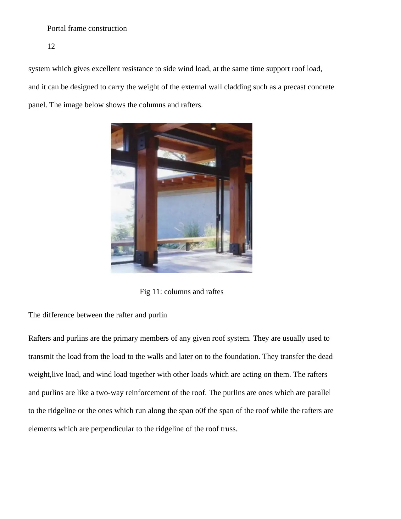
panel. The image below shows the columns and rafters.
Fig 11: columns and raftes
The difference between the rafter and purlin
Rafters and purlins are the primary members of any given roof system. They are usually used to
transmit the load from the load to the walls and later on to the foundation. They transfer the dead
weight,live load, and wind load together with other loads which are acting on them. The rafters
and purlins are like a two-way reinforcement of the roof. The purlins are ones which are parallel
to the ridgeline or the ones which run along the span o0f the span of the roof while the rafters are
elements which are perpendicular to the ridgeline of the roof truss.
12
system which gives excellent resistance to side wind load, at the same time support roof load,
and it can be designed to carry the weight of the external wall cladding such as a precast concrete
panel. The image below shows the columns and rafters.
Fig 11: columns and raftes
The difference between the rafter and purlin
Rafters and purlins are the primary members of any given roof system. They are usually used to
transmit the load from the load to the walls and later on to the foundation. They transfer the dead
weight,live load, and wind load together with other loads which are acting on them. The rafters
and purlins are like a two-way reinforcement of the roof. The purlins are ones which are parallel
to the ridgeline or the ones which run along the span o0f the span of the roof while the rafters are
elements which are perpendicular to the ridgeline of the roof truss.
⊘ This is a preview!⊘
Do you want full access?
Subscribe today to unlock all pages.
Trusted by 1+ million students worldwide
1 out of 32
Related Documents


Your All-in-One AI-Powered Toolkit for Academic Success.
+13062052269
info@desklib.com
Available 24*7 on WhatsApp / Email
![[object Object]](/_next/static/media/star-bottom.7253800d.svg)
Unlock your academic potential
Copyright © 2020–2026 A2Z Services. All Rights Reserved. Developed and managed by ZUCOL.