CPCCBC5018A: Assessment 8 - Factory Complex Footings Report
VerifiedAdded on 2022/10/11
|15
|3066
|14
Report
AI Summary
This report, CPCCBC5018A Assessment 8, provides a comprehensive analysis of footing construction for a factory complex. It details the types of footings used, specifically strip and pad footings, along with their construction methods and sequences, adhering to relevant Australian Standards (AS 2870). The report outlines the necessary plant and equipment for footing construction, including excavators, concrete mixers, and vibrators. Furthermore, it discusses the methods for precise placement and verticality of steel columns, referencing AS 4100 and highlighting the role of surveyors. The report also covers the temporary support of concrete wall panels, emphasizing the use of bracing methods and detailing the bracing setup. The document references figures and standards throughout, providing a practical guide to construction processes and methodologies. The report concludes by emphasizing the importance of planning and adherence to standards in ensuring the structural integrity of the factory complex.
Running head: CPCCBC5018A: ASSESSMENT 8 1
CPCCBC5018A: Assessment 8
Institutional affiliation
First name Last name
CPCCBC5018A: Assessment 8
Institutional affiliation
First name Last name
Paraphrase This Document
Need a fresh take? Get an instant paraphrase of this document with our AI Paraphraser
CPCCBC5018A: ASSESSMENT 8 2
Footings Detailed on the Plans for Project 3
Building structures are connected to the ground by use of foundations which basically
transfers the loads from the building into the ground. There are different types of foundations
including the shallow and the deep foundations. Deep foundations are normally constructed at a
higher depths and transfers the loads deep into the soil while the shallow foundations are situated
near the surface to transfer the loads at relatively shallow depths of the soil. Shallow foundations
are sometimes referred to as footings and are categorized into strip, pad, cantilever or mat
footings (Anderson, 2018). According to design plans provided for the construction of the
Factory Complex, the pad and strip footings are to be used in the foundations during this project.
The Type of Footing Detailed on the Plans
The construction of the factory complex requires the use of shallow foundations and
therefore various types of footings have been designed for use during constructions (Kim, 2017).
According to the provided plans, two types of footings are provided namely the strip and pad
footings.
According to Halder (2019), strip footing is a type of footing which is used in the load
bearing walls and when the construction involves a series of columns in a row which are very
close to each other. The columns being closely spaced and it is therefore economical that a strip
or continuous footing is provided covering all the columns in the row (Viana da Fonseca,
Buttling, & Coutinho, 2014). In the plan strip footings are provided along the wall and the
columns joining all the units, rooms and the offices in the complex. However, it is important to
note that footing is stiffened with reinforcements and piers of 450 mm diameters are provided in
to the soil strata to provide extra supports bellow the foundation (Far & Flint, 2017) .This due to
CPCCBC5018A: ASSESSMENT 8 3
weak soils under which the building is to be constructed. Section 3 of the Australian Standards,
AS 2870 (2011) provides the various requirements for the design of strip footings for residential
buildings and factory complexes.
According to Killeen (2014), pad footings are usually used in the cases where columns
are largely spaced. Pad footings have been provided in the plans for the construction of the
foundation for the factory complex. Looking at the plans, only a few pad footings are to be
provided especially in the columns that are largely spaced along the loading areas thus not
connected with walls. Rectangular pads are used measuring 600mm x 1200 mm are utilised with
reinforcements bars of Y16 sizes provided at both the top and the bottom. Also, a bar spacing of
200 mm need to be provided during the construction of the footing. The plan also provides for
the inclusion of circular piers in the natural clay strata with piers having a 750 mm diameter such
that the soil bearing strength restricted to a minimum of 250 kPa. The Australian Standards,
AS2870 (2011) provides the requirements for the design of the pad footing under different load
conditions.
Footings Construction Method and Sequence
The requirements for the construction of a strip footings are provided in the sections 6.5
of the Australian Standards AS2870 with size of the footings depending of the loads and the type
of soil under which the structure is to be constructed (Sivakugan, Ameratunga, & Das, 2018).
Some of the conditions that are critical for the construction of both pad and strip footings are that
the foundation should provide 100 kPa of the allowable bearing pressure, the topsoil that contain
grass roots should be completely removed and the excavated trenches should be cleaned and any
water removed before concreted is placed (AS 2870, 2011).
⊘ This is a preview!⊘
Do you want full access?
Subscribe today to unlock all pages.
Trusted by 1+ million students worldwide
CPCCBC5018A: ASSESSMENT 8 4
The general sequence of the construction of the footing involves the excavation of
trenches into the ground around the structure perimeter, depending on the required depth of the
footing typically below the frost line of the soil. This step is followed by the pouring of a thin
concrete of appropriate mix design and thickness at the trench bottom. The concrete is then
allowed for a period of time, typically a day to harden. This provides a flat and clean platform for
the laying of the steel reinforcements and wire mesh for the footings.
The stage next involves the establishment of the footing strip plate through the pouring of
concrete in the laid mesh along the perimeter of the building foundation and allowed to harden.
The reinforcements and formworks are established after the hardening of the footing plate based
on the steel bar details provided in the plan after which the final concrete is poured and allowed
to harden through the curing period. According to the specifications, inspections on the
reinforcements must be carried out by the engineer prior to the pouring of the concrete.
Generally, some of the typical components of the footing after the establishment of the
reinforced concrete pad and strip socket include the 150 mm minimum hard-core, the 150mm
concrete subfloor, a dump proof course, the 100 mm rigid insulation, a 75 mm concrete screed
and a finished foot path or driveway path (Strip Foundation, 2018).
Description of the Type of Plant and Equipment Necessary for Footings Construction
A number of plants and equipment are required in the construction of footings including
the ones needed for trenching, concrete pouring, formworks, reinforcements and the
compactions. Such equipment include excavators, ready mixt concrete plant, plate compactors,
concrete pump, water pumps and bowers ,mechanical activated vibrators ,bar bending machines
Paraphrase This Document
Need a fresh take? Get an instant paraphrase of this document with our AI Paraphraser
CPCCBC5018A: ASSESSMENT 8 5
and dump trucks measuring equipment. Smaller tools such as harmers and pairs of pliers are also
required for the wood formwork installation and linking of steel reinforcements (Priya, 2017).
Excavators are needed for the footing excavations in the establishment of trenches for
accommodating the footings based on the drawings. Concrete mixer plants is used in the mixing
of concrete required in large quantities, concrete pumps convey the mixed concrete to the dug
trenches while the water pumps and bowers provided the require water for mixing concrete.
Also, the mechanical activated vibrators are used in the compaction of the poured concrete for
the minimisation of voids or pores.
The bar bending tools are necessary for measuring, cutting and bending of the
reinforcement steel for the footings. Vibrating Plate compactor is necessary during the
construction of the footing for the compaction of areas around the finished footing foundations.
This compacting equipment can reach such confined points which cannot be accessed by larger
vibrating rollers during constructions. The dump trucks transport he needed materials and
equipment to the construction site and the excavated soil to the dumping sites. It is however
worth noting that there are other smaller tools that the builders should equip themselves with
including levelling tools.
Method for the Placement of Steel Columns for Precise Placement and Verticality
The various methods for placing steel columns accurately and vertically are provided by
the Australian Standards AS4100.According to Higgs (2015), the Structural, Mechanical and
Engineering surveyors are tasked with ensuring the precise vertical positions of steel structures
such as the steel columns. The methods used by the surveyors in determination of verticality
CPCCBC5018A: ASSESSMENT 8 6
depends on various factors including the site conditions, the available equipment and the time
constraints. The methods for the determination of correct placement and verticality during the
placement of the steel columns includes both traditional and modern technologies including
positioning, plumbing and the remote methodologies.
The accuracy of the methods are determined based on the section 15.3.2 of the AS 4100 ,
which states that the deviation of a steel column base from its value should not exceed 6 mm
along the principal axes with reference to its position plan. Also, the deviation of any of the
points above the compression member that is the column should not be more than height/500
(AS 4100, 1998).
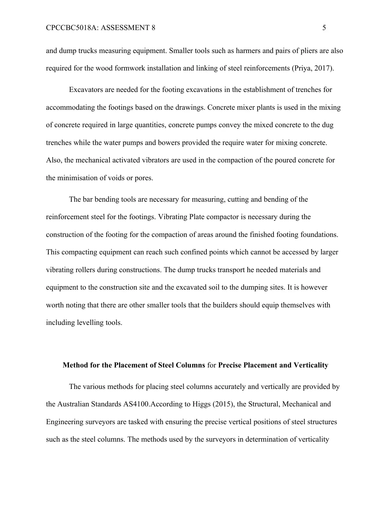
Looking at the positioning, the engineers need to ensure that the anchor bolts are
correctly positioned during the placement of the steel column. However, only correct positioning
of bolts may not guarantee accuracy due to construction variations .Therefore, other calculations
of the column positions are necessary such as mearing the width and the breath of the column
then marking the centre points. The positions of the marked points are then calculated relative to
the positions provided in the design. For instance having a column A, when the measures are
made in the X and Y exes it is found that the column deviates from its design positions to be
4mm and 2 mm in the Y and X axes respectively. According to AS 4100 the measurements are
within +/- 6mm therefore the column correctly placed (Higgs, 2015).
depends on various factors including the site conditions, the available equipment and the time
constraints. The methods for the determination of correct placement and verticality during the
placement of the steel columns includes both traditional and modern technologies including
positioning, plumbing and the remote methodologies.
The accuracy of the methods are determined based on the section 15.3.2 of the AS 4100 ,
which states that the deviation of a steel column base from its value should not exceed 6 mm
along the principal axes with reference to its position plan. Also, the deviation of any of the
points above the compression member that is the column should not be more than height/500
(AS 4100, 1998).
Looking at the positioning, the engineers need to ensure that the anchor bolts are
correctly positioned during the placement of the steel column. However, only correct positioning
of bolts may not guarantee accuracy due to construction variations .Therefore, other calculations
of the column positions are necessary such as mearing the width and the breath of the column
then marking the centre points. The positions of the marked points are then calculated relative to
the positions provided in the design. For instance having a column A, when the measures are
made in the X and Y exes it is found that the column deviates from its design positions to be
4mm and 2 mm in the Y and X axes respectively. According to AS 4100 the measurements are
within +/- 6mm therefore the column correctly placed (Higgs, 2015).
⊘ This is a preview!⊘
Do you want full access?
Subscribe today to unlock all pages.
Trusted by 1+ million students worldwide
CPCCBC5018A: ASSESSMENT 8 7
Figure 1: Column Positioning
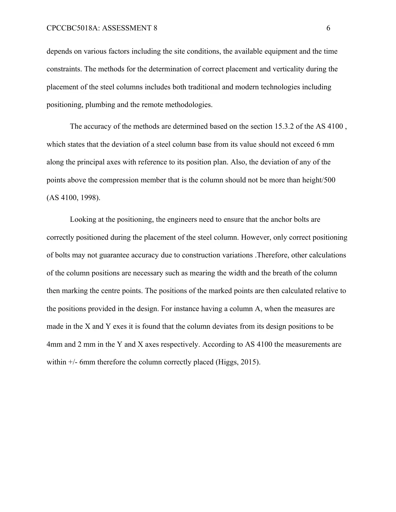
The verticality of the column should now be ensured after correct positioning and some
of the methods of ensuring verticality is the use of plumb bob, the total station, the spirit levels
and the mote methods. The plum bob and spirit methods involves the placement of the spirit
levels directly on the column and checking its verticality as shown in figure 2.
Figure 2: Column Verticality by Plumbing and Spirit Level
Figure 1: Column Positioning
The verticality of the column should now be ensured after correct positioning and some
of the methods of ensuring verticality is the use of plumb bob, the total station, the spirit levels
and the mote methods. The plum bob and spirit methods involves the placement of the spirit
levels directly on the column and checking its verticality as shown in figure 2.
Figure 2: Column Verticality by Plumbing and Spirit Level
Paraphrase This Document
Need a fresh take? Get an instant paraphrase of this document with our AI Paraphraser
CPCCBC5018A: ASSESSMENT 8 8
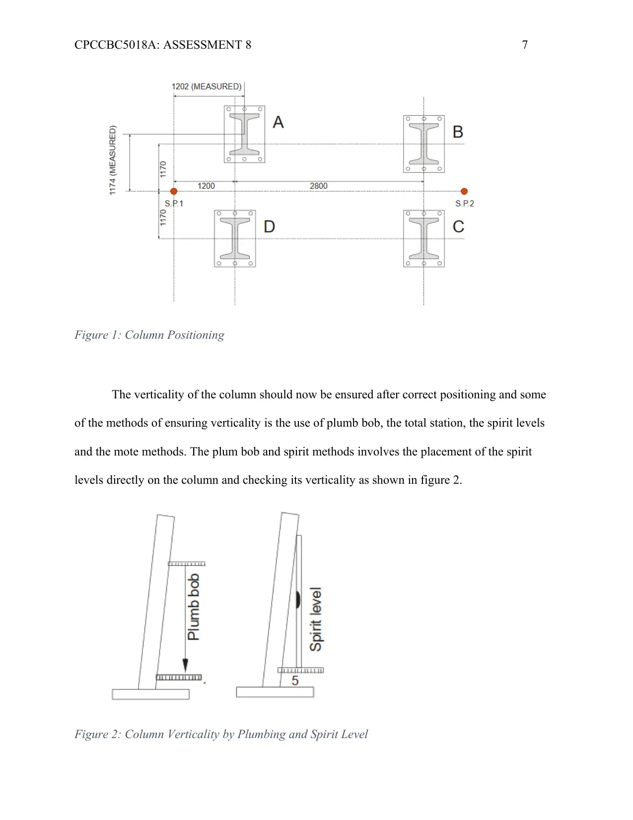
The remote methodology is important in cases where high accuracies are needed and the
access difficulties. This method involves the use of digital machines and software which utilize
the total station techniques where the machine is strategically positioned to pick chainages or
points which are interpreted and drawn using the Computer-Aided Drafting software.
Figure 3: Remote Methodology
Suitable Method for the Temporary Support of the Concrete Wall Panels (For Project 3)
The process of erection and connection of concrete wall panels calls for proper planning
to ensure that everything is provided for during the process. The items that need to be adequately
planned for include the methods of assembly and erection of the panels, the method of temporary
support provision, final structural connections provision, the erection tolerance based on codes
and the handling requirements such as adequate cranes (BCA-Australia,2015).
CPCCBC5018A: ASSESSMENT 8 9
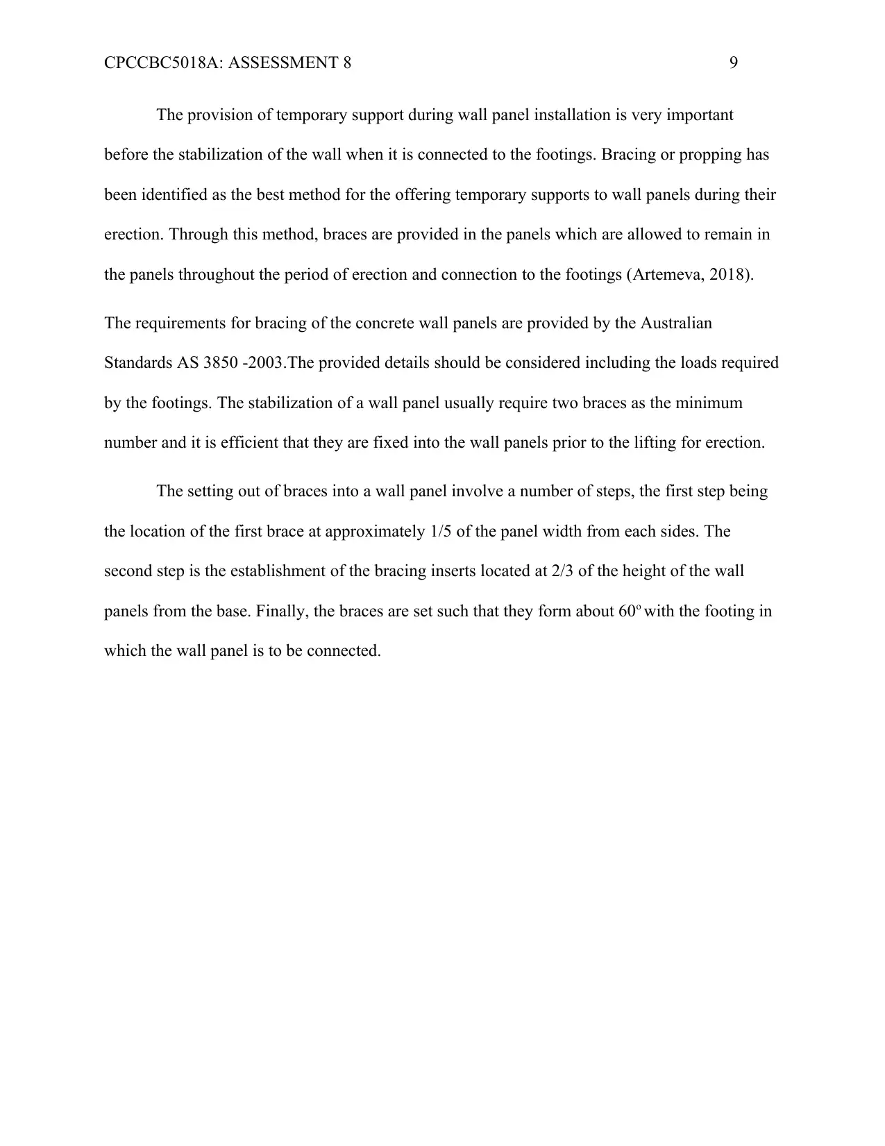
The provision of temporary support during wall panel installation is very important
before the stabilization of the wall when it is connected to the footings. Bracing or propping has
been identified as the best method for the offering temporary supports to wall panels during their
erection. Through this method, braces are provided in the panels which are allowed to remain in
the panels throughout the period of erection and connection to the footings (Artemeva, 2018).
The requirements for bracing of the concrete wall panels are provided by the Australian
Standards AS 3850 -2003.The provided details should be considered including the loads required
by the footings. The stabilization of a wall panel usually require two braces as the minimum
number and it is efficient that they are fixed into the wall panels prior to the lifting for erection.
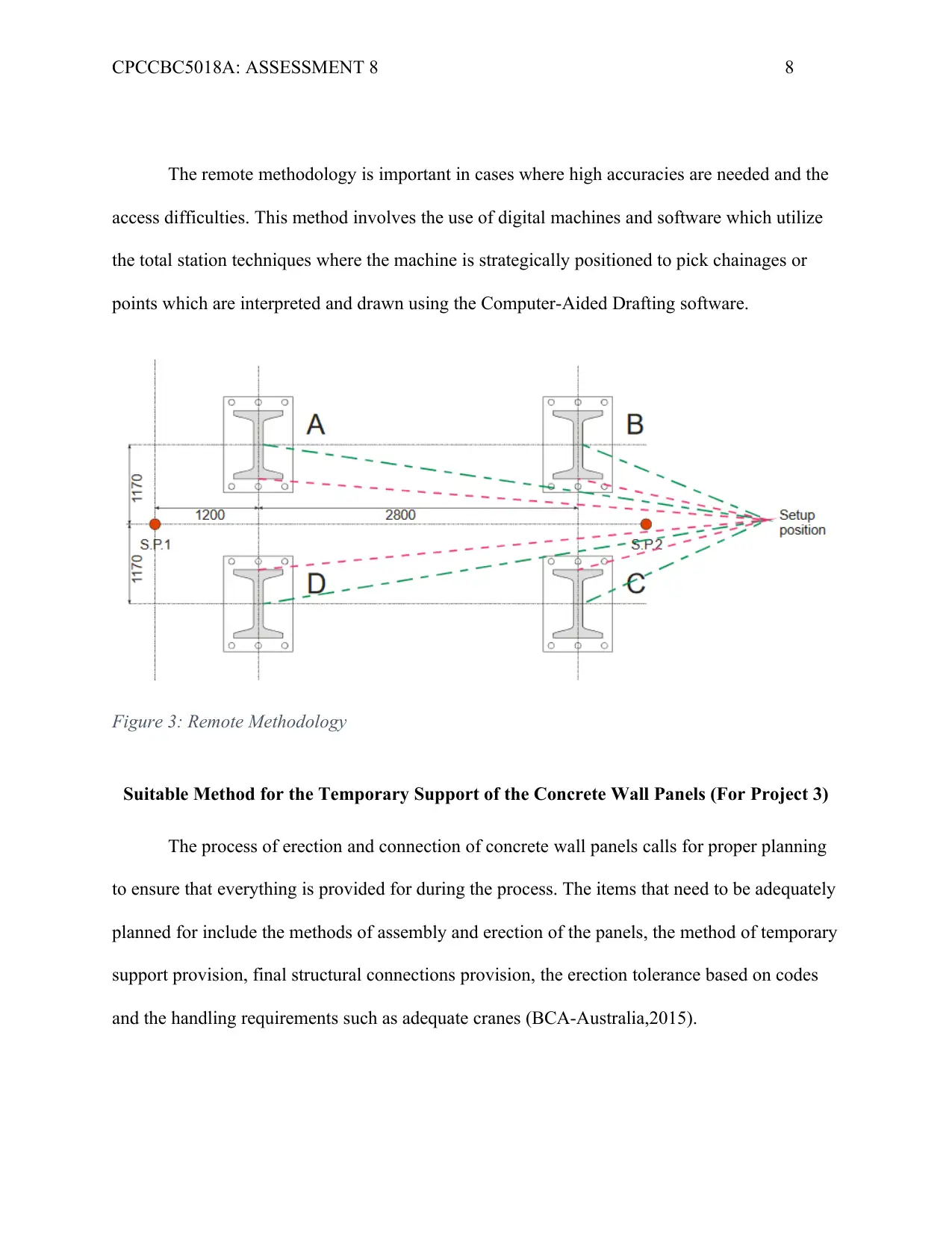
The setting out of braces into a wall panel involve a number of steps, the first step being
the location of the first brace at approximately 1/5 of the panel width from each sides. The
second step is the establishment of the bracing inserts located at 2/3 of the height of the wall
panels from the base. Finally, the braces are set such that they form about 60o with the footing in
which the wall panel is to be connected.
The provision of temporary support during wall panel installation is very important
before the stabilization of the wall when it is connected to the footings. Bracing or propping has
been identified as the best method for the offering temporary supports to wall panels during their
erection. Through this method, braces are provided in the panels which are allowed to remain in
the panels throughout the period of erection and connection to the footings (Artemeva, 2018).
The requirements for bracing of the concrete wall panels are provided by the Australian
Standards AS 3850 -2003.The provided details should be considered including the loads required
by the footings. The stabilization of a wall panel usually require two braces as the minimum
number and it is efficient that they are fixed into the wall panels prior to the lifting for erection.
The setting out of braces into a wall panel involve a number of steps, the first step being
the location of the first brace at approximately 1/5 of the panel width from each sides. The
second step is the establishment of the bracing inserts located at 2/3 of the height of the wall
panels from the base. Finally, the braces are set such that they form about 60o with the footing in
which the wall panel is to be connected.
⊘ This is a preview!⊘
Do you want full access?
Subscribe today to unlock all pages.
Trusted by 1+ million students worldwide
CPCCBC5018A: ASSESSMENT 8 10
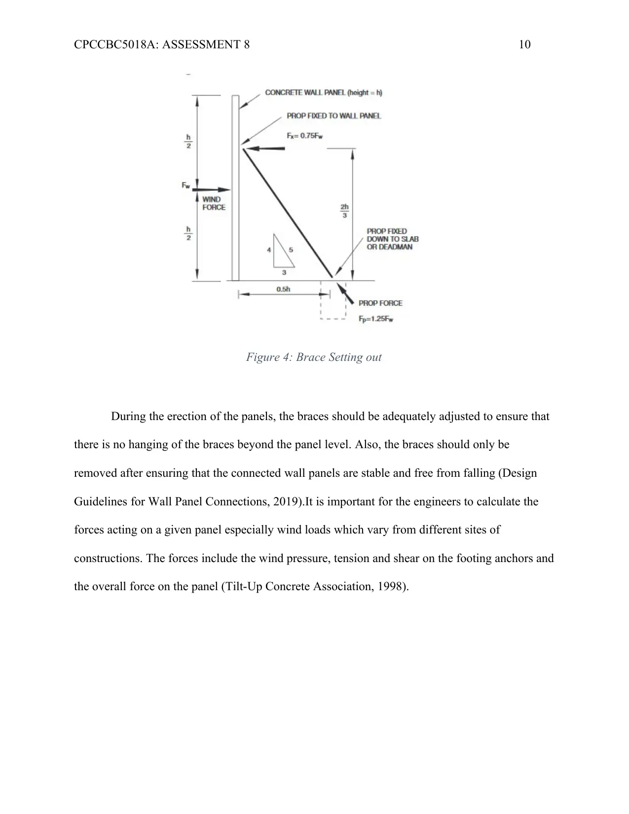
Figure 4: Brace Setting out
During the erection of the panels, the braces should be adequately adjusted to ensure that
there is no hanging of the braces beyond the panel level. Also, the braces should only be
removed after ensuring that the connected wall panels are stable and free from falling (Design
Guidelines for Wall Panel Connections, 2019).It is important for the engineers to calculate the
forces acting on a given panel especially wind loads which vary from different sites of
constructions. The forces include the wind pressure, tension and shear on the footing anchors and
the overall force on the panel (Tilt-Up Concrete Association, 1998).
Paraphrase This Document
Need a fresh take? Get an instant paraphrase of this document with our AI Paraphraser
CPCCBC5018A: ASSESSMENT 8 11
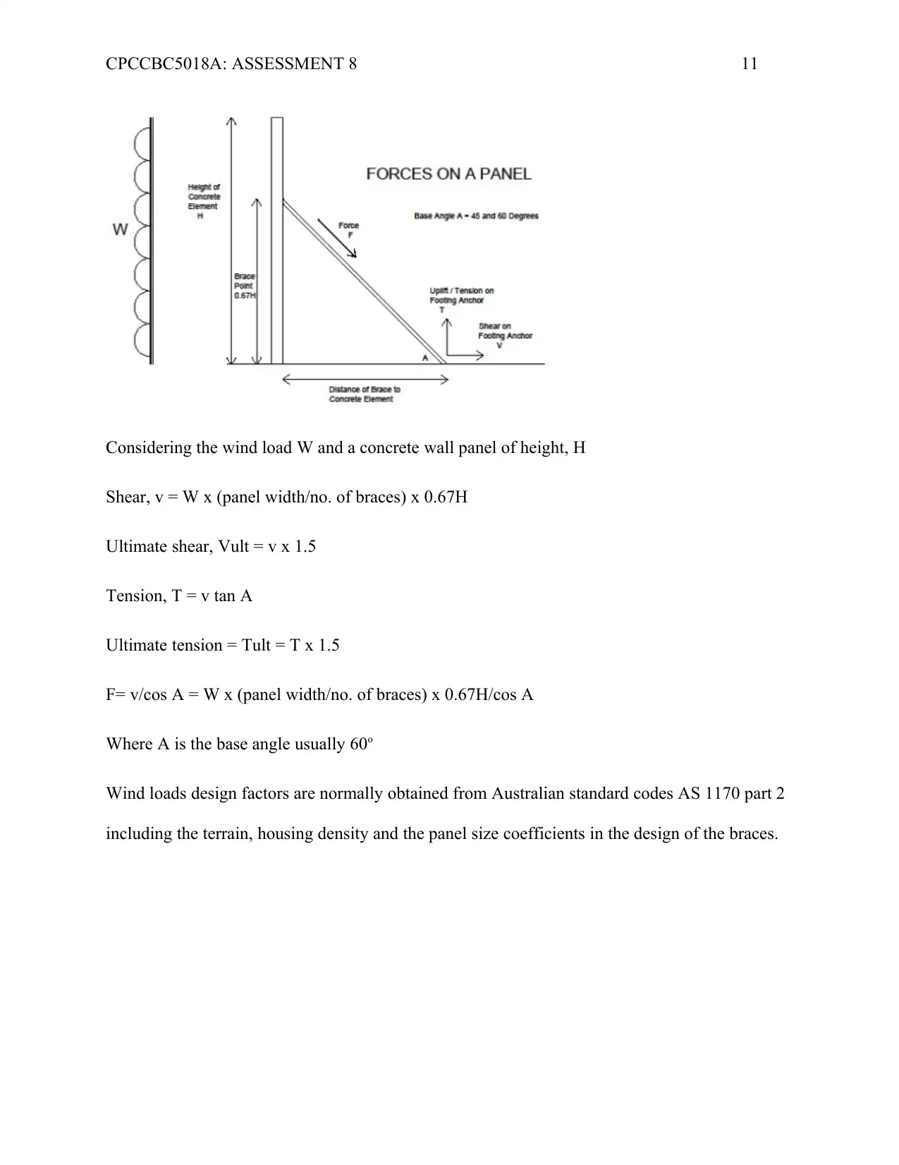
Considering the wind load W and a concrete wall panel of height, H
Shear, v = W x (panel width/no. of braces) x 0.67H
Ultimate shear, Vult = v x 1.5
Tension, T = v tan A
Ultimate tension = Tult = T x 1.5
F= v/cos A = W x (panel width/no. of braces) x 0.67H/cos A
Where A is the base angle usually 60o
Wind loads design factors are normally obtained from Australian standard codes AS 1170 part 2
including the terrain, housing density and the panel size coefficients in the design of the braces.
CPCCBC5018A: ASSESSMENT 8 12
The Need for Termite Protection for the Building in Project 2 (Medium Rise Apartments)
Termites have been identified as a major causes of damages to buildings and homes and
therefore new buildings must be protected from them. The methods of protecting buildings
against termites include the use of barriers such as granular and sheet materials and use of
chemicals (Victorian Building Authority, 2019). The Building Codes of Australia provides for
various elements of a building and the corresponding termite management systems. According to
the code, building elements such as the ground concrete slab, the suspended floors and the
various attachments to the building should be provided with a termite management system. Also,
the Australian Standards AS 3660.1 outlines the requirements for various termite management
systems.
The slab perimeter of the ground floor ,various penetrations or joints and the areas below
the slab the of the medium rise apartments need termite protection by use of components such as
use of sheet an granular material or chemicals during the construction of the ground slab. The
footing systems of the building should also be protected (BCA-2015).
⊘ This is a preview!⊘
Do you want full access?
Subscribe today to unlock all pages.
Trusted by 1+ million students worldwide
1 out of 15
Related Documents


Your All-in-One AI-Powered Toolkit for Academic Success.
+13062052269
info@desklib.com
Available 24*7 on WhatsApp / Email
![[object Object]](/_next/static/media/star-bottom.7253800d.svg)
Unlock your academic potential
Copyright © 2020–2026 A2Z Services. All Rights Reserved. Developed and managed by ZUCOL.