Faculty of Science: Crane Design and Analysis Report (2018)
VerifiedAdded on 2020/05/16
|14
|2345
|156
Report
AI Summary
This report provides a preliminary design and analysis of a single girder overhead traveling crane, adhering to BS EN 1991-3:2006 and BS EN 1993-6:2007 standards. The objective was to determine the strength characteristics of the crane by considering live and dead loads and stress endurance. The report details the design calculations, including bending moment, shear force, and deflection analysis using singularity functions and equivalent stress techniques. The design data includes a 6m crane bridge span and a 3.2tn lifting capacity. The system constraints such as maximum vertical displacement and stress limits are defined. Assumptions include a simply supported beam and uniform loading. The report also includes the selection of a suitable bridge girder profile (S15x42.9) and concludes that the design is safe within the given constraints but recommends considering dynamic conditions for future designs.
Faculty of Science, Engineering and Computing
Preliminary Design of a Single girder overhead traveling Crane
As per BS EN 1991-3:2006 and BS EN 1993-6:2007
Prepared By: YXZ
Dated: 23rd February 2018
Mechanical System –OT Crane design Page 1
Preliminary Design of a Single girder overhead traveling Crane
As per BS EN 1991-3:2006 and BS EN 1993-6:2007
Prepared By: YXZ
Dated: 23rd February 2018
Mechanical System –OT Crane design Page 1
Paraphrase This Document
Need a fresh take? Get an instant paraphrase of this document with our AI Paraphraser
EXECUTIVE SUMMARY
Normally cranes come in different sizes and configurations. In this report, we considered an
Overhead Traveling (OT) crane often referred to as ‘bridge crane’. The objective was to
underscore the strength characteristics of the crane by considering the live and dead loads and
stress endurance limit of the system under consideration. A major design to size and select the
dimensions of the bridge girder was undertaken and interesting results were realized. Notably,
this was a preliminary design and analysis report whose aim was mainly to undertake the design
calculation and illustrate N-Q-M diagrams by applying the singularity-functions methods and the
equivalent stress techniques; then it was based on a real-life engineering application. In
conclusion section, the need to undertake some system design improvements was emphasized.
Mechanical System –OT Crane design Page 2
1. INTRODUCTION
An Overhead Traveling (OT) crane or rather commonly referred to as ‘bridge crane’ is normally
configured by having parallel runways such that the gap between the rails is spanned by a
horizontally traveling bridge. The degree of freedom is restricted only in the x-y plane such that
the bridge moves in the longitudinal direction. The crane has got a hoist which does the lifting of
objects via electrically excited system. The trolley therefore moves horizontally on the beam
bridge. Admittedly, these crane types have found wide applications in various industries such as
shipping, machining and other industrial stations and whose major functionality is to lift and
move heavy objects like wheels of bogies among others. For instance, in the rolling stock
industry, the OT crane is used to facilitate replacement of old wheel and axles of bogies
(Globalspec.com, 2018). The bridge is normally built using either plate welding or hot rolling of
steel (Cranes, 2018). However, most of commercially available steel material comes from hot
rolling which itself is an opportunity to provide sufficient structural integrity of the bridge. The
strength of the beam must be adequate to carry the live and dead loads and endure the various
stresses as the system is in operation (Directindustry.com, 2018). Therefore, hereinafter, a major
design to size and select the dimensions of the bridge girder ensues. This is a preliminary design
and analysis report whose aim is to: undertake the design calculation and illustrate N-Q-M
diagrams by applying the singularity-functions methods and the equivalent stress techniques;
then we base it in a real-life engineering application (Mathalino.com, 2018).
Mechanical System –OT Crane design Page 3
⊘ This is a preview!⊘
Do you want full access?
Subscribe today to unlock all pages.
Trusted by 1+ million students worldwide
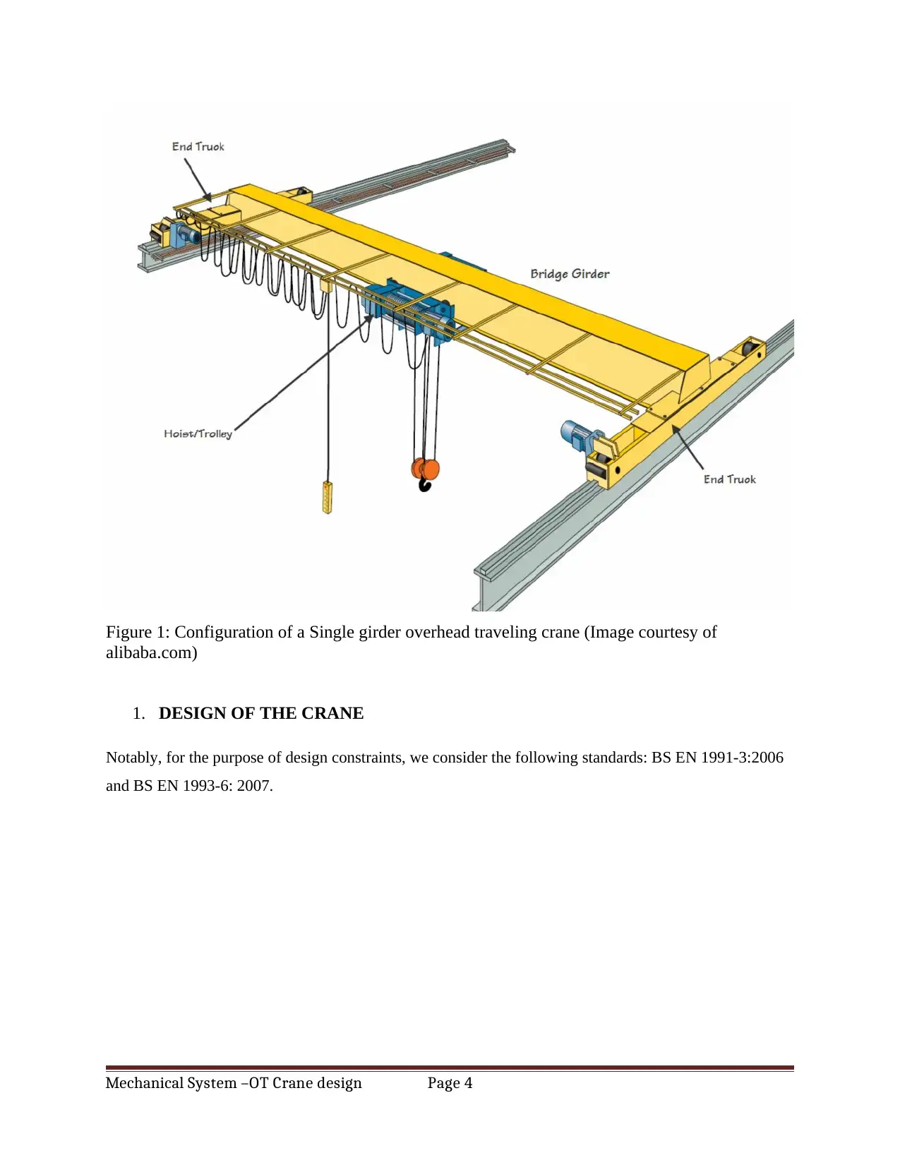
Figure 1: Configuration of a Single girder overhead traveling crane (Image courtesy of
alibaba.com)
1. DESIGN OF THE CRANE
Notably, for the purpose of design constraints, we consider the following standards: BS EN 1991-3:2006
and BS EN 1993-6: 2007.
Mechanical System –OT Crane design Page 4
alibaba.com)
1. DESIGN OF THE CRANE
Notably, for the purpose of design constraints, we consider the following standards: BS EN 1991-3:2006
and BS EN 1993-6: 2007.
Mechanical System –OT Crane design Page 4
Paraphrase This Document
Need a fresh take? Get an instant paraphrase of this document with our AI Paraphraser
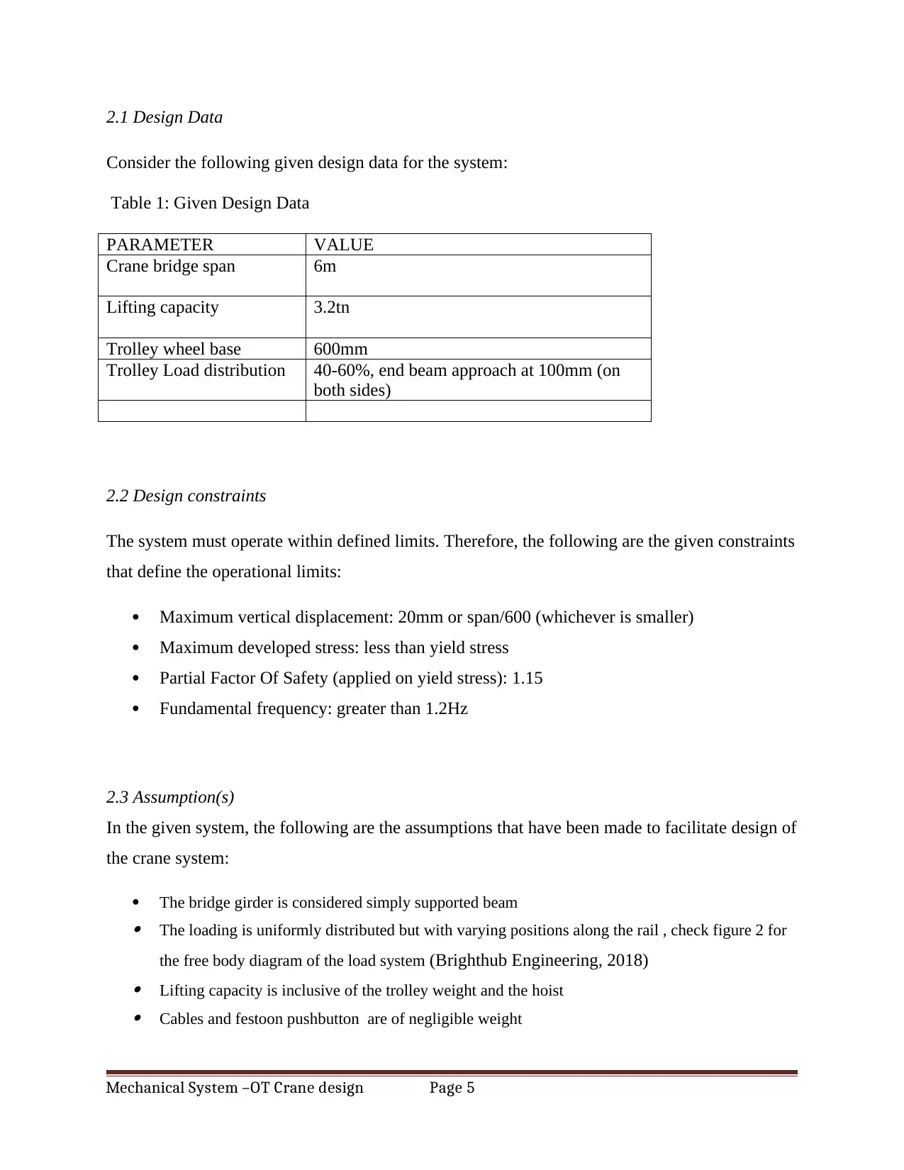
2.1 Design Data
Consider the following given design data for the system:
Table 1: Given Design Data
PARAMETER VALUE
Crane bridge span 6m
Lifting capacity 3.2tn
Trolley wheel base 600mm
Trolley Load distribution 40-60%, end beam approach at 100mm (on
both sides)
2.2 Design constraints
The system must operate within defined limits. Therefore, the following are the given constraints
that define the operational limits:
Maximum vertical displacement: 20mm or span/600 (whichever is smaller)
Maximum developed stress: less than yield stress
Partial Factor Of Safety (applied on yield stress): 1.15
Fundamental frequency: greater than 1.2Hz
2.3 Assumption(s)
In the given system, the following are the assumptions that have been made to facilitate design of
the crane system:
The bridge girder is considered simply supported beam The loading is uniformly distributed but with varying positions along the rail , check figure 2 for
the free body diagram of the load system (Brighthub Engineering, 2018) Lifting capacity is inclusive of the trolley weight and the hoist Cables and festoon pushbutton are of negligible weight
Mechanical System –OT Crane design Page 5
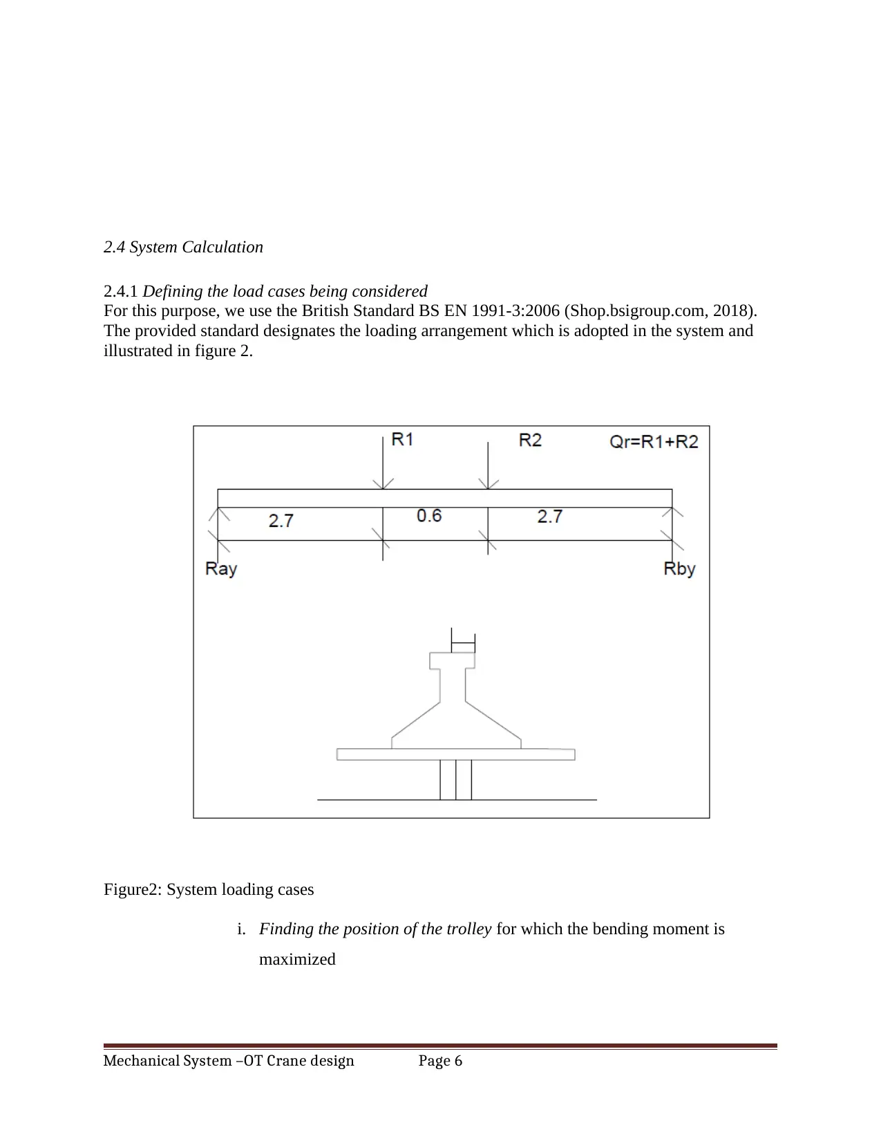
2.4 System Calculation
2.4.1 Defining the load cases being considered
For this purpose, we use the British Standard BS EN 1991-3:2006 (Shop.bsigroup.com, 2018).
The provided standard designates the loading arrangement which is adopted in the system and
illustrated in figure 2.
Figure2: System loading cases
i. Finding the position of the trolley for which the bending moment is
maximized
Mechanical System –OT Crane design Page 6
⊘ This is a preview!⊘
Do you want full access?
Subscribe today to unlock all pages.
Trusted by 1+ million students worldwide
From the given data, we know that the rail shares the load in the ration of 40 to 60% hence
correspondingly R1 and R2 are determined:
But Qr= total loading (equivalent to the lifting loading plus other weight components)=
3.2x9.81=31.392 (fix at 31.4kN)
R1= 0.4x31.4= 12.56kN
R2= 0.6x 31.4= 18.84kN
Next, we find the reactions at supports A and B shown in the FBD figure 2
Given the system is at static equilibrium such that:
Ray+Rby=R1+R2=Qr and with a little consideration from the FBD we see that the reactions are
actually sharing the load equally hence: R1=R2= Qr/2= 31.4/2=15.7kN
We then find the Bending moment equation by considering moments about A:
Ma= -12.56x-18.84(x+d1)+15.7x6
= -12.56x-18.84x-18.84d1)+94.2
Ma= -31.4x +82.896….(i)
For the position of maximum bending moment, we put equation (i) as being equal to 0 hence:
-31.4(x) +82.896= 0; -31.4x=-82.896, x= 2.64 (that is 2.64m from point A as shown in
figure2)
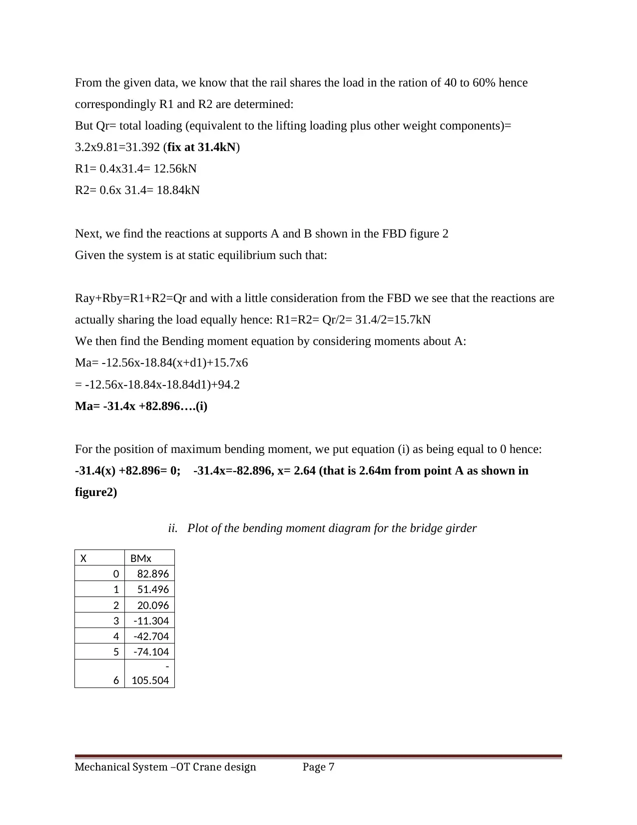
ii. Plot of the bending moment diagram for the bridge girder
X BMx
0 82.896
1 51.496
2 20.096
3 -11.304
4 -42.704
5 -74.104
6
-
105.504
Mechanical System –OT Crane design Page 7
correspondingly R1 and R2 are determined:
But Qr= total loading (equivalent to the lifting loading plus other weight components)=
3.2x9.81=31.392 (fix at 31.4kN)
R1= 0.4x31.4= 12.56kN
R2= 0.6x 31.4= 18.84kN
Next, we find the reactions at supports A and B shown in the FBD figure 2
Given the system is at static equilibrium such that:
Ray+Rby=R1+R2=Qr and with a little consideration from the FBD we see that the reactions are
actually sharing the load equally hence: R1=R2= Qr/2= 31.4/2=15.7kN
We then find the Bending moment equation by considering moments about A:
Ma= -12.56x-18.84(x+d1)+15.7x6
= -12.56x-18.84x-18.84d1)+94.2
Ma= -31.4x +82.896….(i)
For the position of maximum bending moment, we put equation (i) as being equal to 0 hence:
-31.4(x) +82.896= 0; -31.4x=-82.896, x= 2.64 (that is 2.64m from point A as shown in
figure2)
ii. Plot of the bending moment diagram for the bridge girder
X BMx
0 82.896
1 51.496
2 20.096
3 -11.304
4 -42.704
5 -74.104
6
-
105.504
Mechanical System –OT Crane design Page 7
Paraphrase This Document
Need a fresh take? Get an instant paraphrase of this document with our AI Paraphraser
0 1 2 3 4 5 6
-150
-100
-50
0
50
100
BMx
BMx
Figure 3: Bending moment diagram
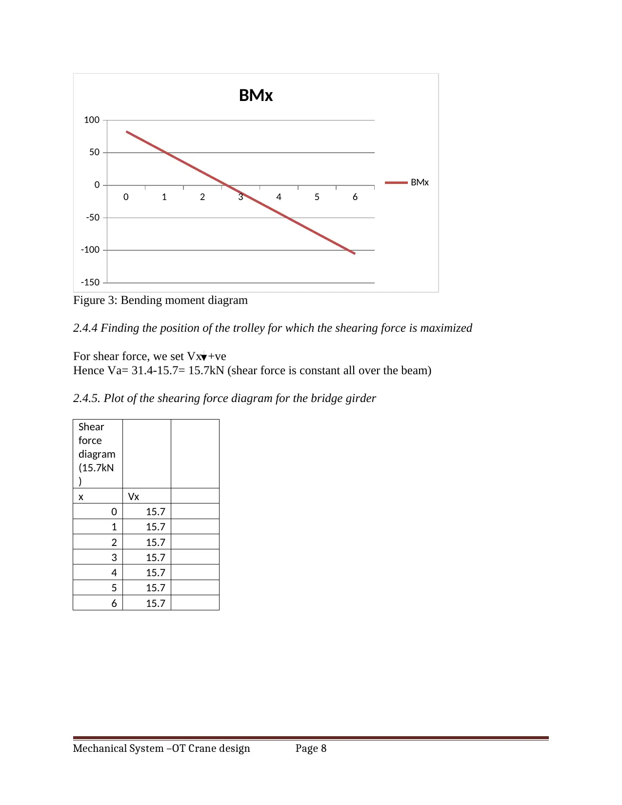
2.4.4 Finding the position of the trolley for which the shearing force is maximized
For shear force, we set Vx +ve
Hence Va= 31.4-15.7= 15.7kN (shear force is constant all over the beam)
2.4.5. Plot of the shearing force diagram for the bridge girder
Shear
force
diagram
(15.7kN
)
x Vx
0 15.7
1 15.7
2 15.7
3 15.7
4 15.7
5 15.7
6 15.7
Mechanical System –OT Crane design Page 8
-150
-100
-50
0
50
100
BMx
BMx
Figure 3: Bending moment diagram
2.4.4 Finding the position of the trolley for which the shearing force is maximized
For shear force, we set Vx +ve
Hence Va= 31.4-15.7= 15.7kN (shear force is constant all over the beam)
2.4.5. Plot of the shearing force diagram for the bridge girder
Shear
force
diagram
(15.7kN
)
x Vx
0 15.7
1 15.7
2 15.7
3 15.7
4 15.7
5 15.7
6 15.7
Mechanical System –OT Crane design Page 8
0 1 2 3 4 5 6
0
2
4
6
8
10
12
14
16
18
Vx
Vx
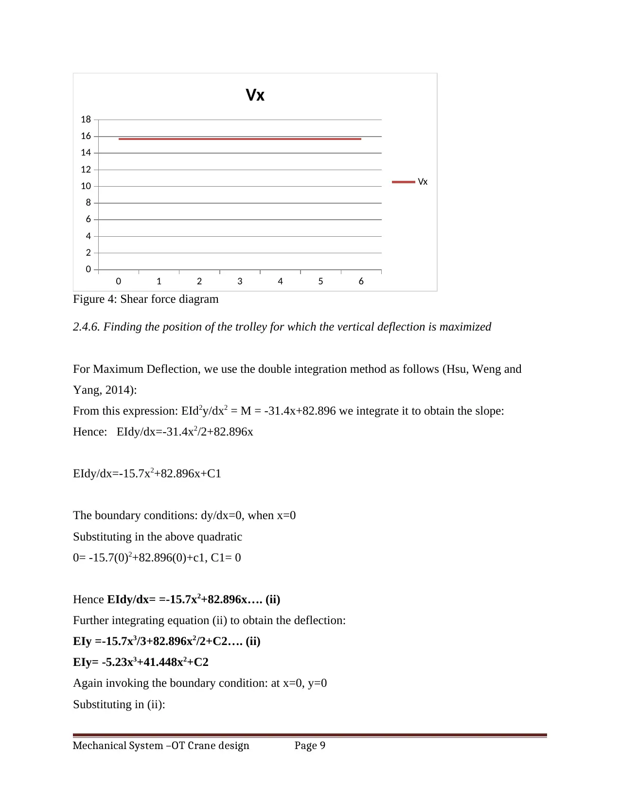
Figure 4: Shear force diagram
2.4.6. Finding the position of the trolley for which the vertical deflection is maximized
For Maximum Deflection, we use the double integration method as follows (Hsu, Weng and
Yang, 2014):
From this expression: EId2y/dx2 = M = -31.4x+82.896 we integrate it to obtain the slope:
Hence: EIdy/dx=-31.4x2/2+82.896x
EIdy/dx=-15.7x2+82.896x+C1
The boundary conditions: dy/dx=0, when x=0
Substituting in the above quadratic
0= -15.7(0)2+82.896(0)+c1, C1= 0
Hence EIdy/dx= =-15.7x2+82.896x…. (ii)
Further integrating equation (ii) to obtain the deflection:
EIy =-15.7x3/3+82.896x2/2+C2…. (ii)
EIy= -5.23x3+41.448x2+C2
Again invoking the boundary condition: at x=0, y=0
Substituting in (ii):
Mechanical System –OT Crane design Page 9
0
2
4
6
8
10
12
14
16
18
Vx
Vx
Figure 4: Shear force diagram
2.4.6. Finding the position of the trolley for which the vertical deflection is maximized
For Maximum Deflection, we use the double integration method as follows (Hsu, Weng and
Yang, 2014):
From this expression: EId2y/dx2 = M = -31.4x+82.896 we integrate it to obtain the slope:
Hence: EIdy/dx=-31.4x2/2+82.896x
EIdy/dx=-15.7x2+82.896x+C1
The boundary conditions: dy/dx=0, when x=0
Substituting in the above quadratic
0= -15.7(0)2+82.896(0)+c1, C1= 0
Hence EIdy/dx= =-15.7x2+82.896x…. (ii)
Further integrating equation (ii) to obtain the deflection:
EIy =-15.7x3/3+82.896x2/2+C2…. (ii)
EIy= -5.23x3+41.448x2+C2
Again invoking the boundary condition: at x=0, y=0
Substituting in (ii):
Mechanical System –OT Crane design Page 9
⊘ This is a preview!⊘
Do you want full access?
Subscribe today to unlock all pages.
Trusted by 1+ million students worldwide
0=-5.23(0)3+41.448(0)2+C2
0= +C2
Hence the slope equation: dy/dx =-5.23x3+41.448x2… (iii)
For maximum deflection, we differentiate or rather we pick the slope equation (ii) and equate to
zero hence:
EIdy==-15.7x2+82.896x=0
X(82.896-15.7x)= 0
X=0, or x=-82.896/15.7=5.22
We take the latter as it is more practical considering the system in figure 2 hence position is at
5.22m from point A
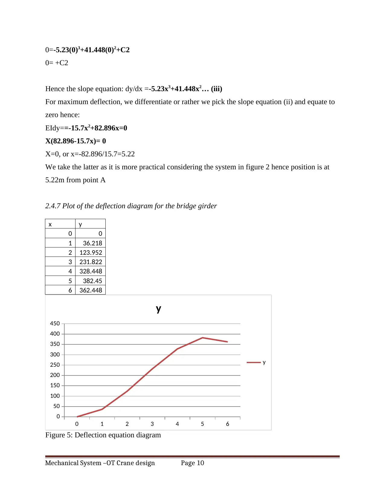
2.4.7 Plot of the deflection diagram for the bridge girder
x y
0 0
1 36.218
2 123.952
3 231.822
4 328.448
5 382.45
6 362.448
0 1 2 3 4 5 6
0
50
100
150
200
250
300
350
400
450
y
y
Figure 5: Deflection equation diagram
Mechanical System –OT Crane design Page 10
0= +C2
Hence the slope equation: dy/dx =-5.23x3+41.448x2… (iii)
For maximum deflection, we differentiate or rather we pick the slope equation (ii) and equate to
zero hence:
EIdy==-15.7x2+82.896x=0
X(82.896-15.7x)= 0
X=0, or x=-82.896/15.7=5.22
We take the latter as it is more practical considering the system in figure 2 hence position is at
5.22m from point A
2.4.7 Plot of the deflection diagram for the bridge girder
x y
0 0
1 36.218
2 123.952
3 231.822
4 328.448
5 382.45
6 362.448
0 1 2 3 4 5 6
0
50
100
150
200
250
300
350
400
450
y
y
Figure 5: Deflection equation diagram
Mechanical System –OT Crane design Page 10
Paraphrase This Document
Need a fresh take? Get an instant paraphrase of this document with our AI Paraphraser
2.4.8. For the defined load cases and the selected positions:
(a) Estimating the corresponding stresses
First we need to go back to the position at which maximum deflection occurs hence x=5.22 is the
position and we substitute in the bending moment equation:
M= -31.4(5.22)+ 82.896= -81.012kNm
Now we need to size the beam hence from this expression, we can get the moment of Inertia I
(Codecogs.com, 2018):
M/I=E/R
I= MR/E
Taking E= 203GPa and R= 300/2=150mm (neutral axis)
I= 81.012 x 0.15/203x109= 5.986x10⁻¹¹m4
Fixing b at 0.3, d can be found since we know: I= bd3/12 (assume rectangular section)
Hence d= {(12x 5.986x10-11)/0.3}1/3= 1.338m
Now, Ax= 6x 1.338= 8.028m2
And Az= 0.3 x 6= 1.8m2
Hence:
Local shear stress τ,Ed
= Qr/Ay= 31.4/(0.3x 1.338)= 78.226MPa
Longitudinal stress σx,Ed
= Qr/Ax= 31.4/1.8= 17.44MPa
Traverse stress σz,Ed
= Qr/Az= 31.4/8.028= 3.911MPa
Yield stress fy
=200MPa, fy/Ym= 200/1.15= 173.91MPa
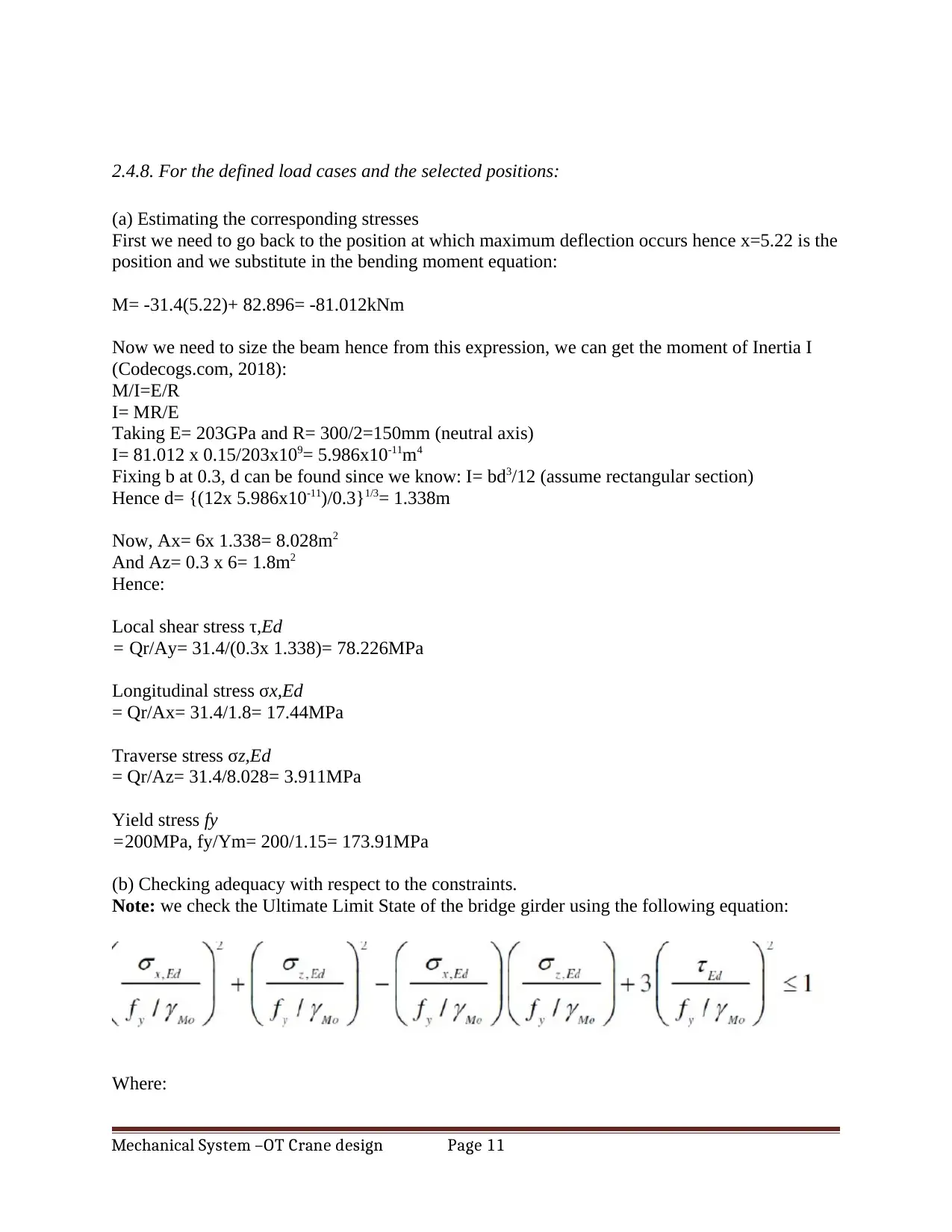
(b) Checking adequacy with respect to the constraints.
Note: we check the Ultimate Limit State of the bridge girder using the following equation:
Where:
Mechanical System –OT Crane design Page 11
(a) Estimating the corresponding stresses
First we need to go back to the position at which maximum deflection occurs hence x=5.22 is the
position and we substitute in the bending moment equation:
M= -31.4(5.22)+ 82.896= -81.012kNm
Now we need to size the beam hence from this expression, we can get the moment of Inertia I
(Codecogs.com, 2018):
M/I=E/R
I= MR/E
Taking E= 203GPa and R= 300/2=150mm (neutral axis)
I= 81.012 x 0.15/203x109= 5.986x10⁻¹¹m4
Fixing b at 0.3, d can be found since we know: I= bd3/12 (assume rectangular section)
Hence d= {(12x 5.986x10-11)/0.3}1/3= 1.338m
Now, Ax= 6x 1.338= 8.028m2
And Az= 0.3 x 6= 1.8m2
Hence:
Local shear stress τ,Ed
= Qr/Ay= 31.4/(0.3x 1.338)= 78.226MPa
Longitudinal stress σx,Ed
= Qr/Ax= 31.4/1.8= 17.44MPa
Traverse stress σz,Ed
= Qr/Az= 31.4/8.028= 3.911MPa
Yield stress fy
=200MPa, fy/Ym= 200/1.15= 173.91MPa
(b) Checking adequacy with respect to the constraints.
Note: we check the Ultimate Limit State of the bridge girder using the following equation:
Where:
Mechanical System –OT Crane design Page 11
σx,Ed: design value of the local longitudinal stress at the point of consideration
σz,Ed: design value of the local transverse stress at the point of consideration
τEd: design value of the local shear stress at the point of consideration
fy: yield stress for the selected material
γMo: partial factor of safety
We substitute the respective values in the above expression of constraints:
Let us break into terms:
(ρx/f/γ)2= (17.44/173.91)2= 0.010056
(ρz/f/γ)2 = (3.911/173.91)2 = 5.057x 10⁻⁴
(ρz/f/γ) (ρx/f/γ)= 0.10028x0.02248= 4.4609
3(τ/f/γ) = 3(78.226/173.91) = 0.6069
Checking by substituting in the above expression of constraint:
=0.010056+ 5.057x 10⁻⁴-4.4609+ 0.6069= -3.843<1
Hence the design is safe
2. SELECTION OF THE BRIDGE GIRDER
Based on the design output and using a theoretical approach, we undertake a selection of
a girder bridge profile. It must meet the given design specifications and be of minimum
weight.
From Harrington hoists catalogue (Qu et al., 2014), we select the bridge girder: S15x42.9
with a capacity of 6.1m span and capacity of 3 to 5 tones
3. CONCLUSION
From the foregoing, we can conclude that the design output and the selected
commercially available bridge girder match (bridges, 2018). In the calculation, a capacity
of 3.2 ton and span of 6m was used to design the system by considering the structural
integrity of the bridge girder. From checking of structural constraints, it has been
Mechanical System –OT Crane design Page 12
⊘ This is a preview!⊘
Do you want full access?
Subscribe today to unlock all pages.
Trusted by 1+ million students worldwide
1 out of 14

Your All-in-One AI-Powered Toolkit for Academic Success.
+13062052269
info@desklib.com
Available 24*7 on WhatsApp / Email
![[object Object]](/_next/static/media/star-bottom.7253800d.svg)
Unlock your academic potential
Copyright © 2020–2025 A2Z Services. All Rights Reserved. Developed and managed by ZUCOL.