UCLan MP4706: Crane LMI System Experimental Analysis Report
VerifiedAdded on 2022/09/25
|7
|1435
|17
Report
AI Summary
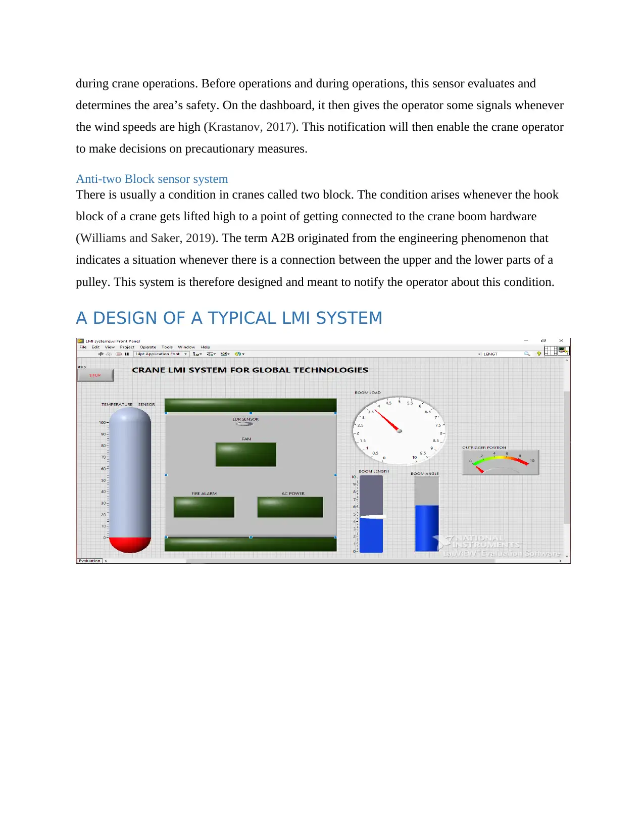
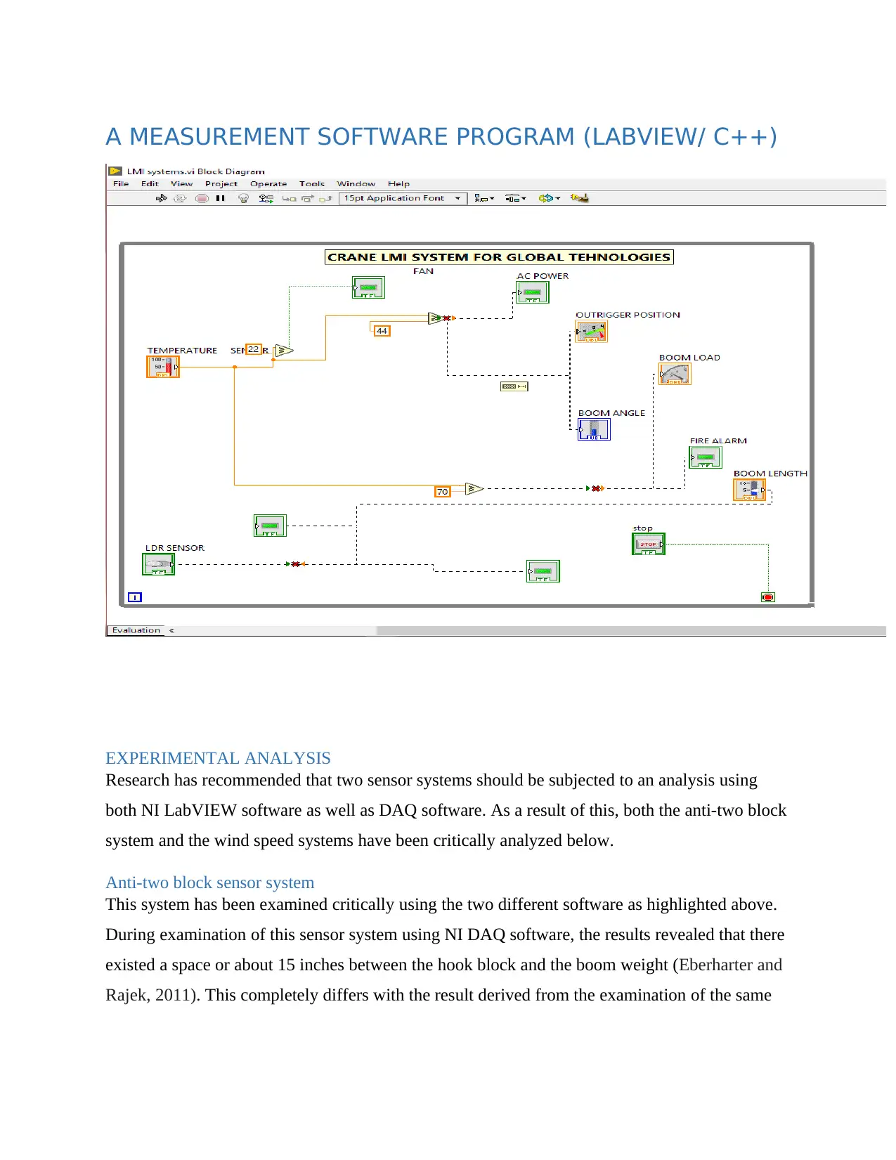
This report provides a comprehensive analysis of a Crane Load Moment Indicator (LMI) system, crucial for hydraulic cranes, and focuses on experimental analysis. The report details the functions of various LMI system components, including load plate systems, angle and length transmitters, angle sensors, wind speed sensors, and anti-two block sensors. The core of the report involves the experimental analysis of anti-two block and wind speed sensor systems using NI LabVIEW and NI DAQ software. The findings highlight differences in results between the two software platforms, emphasizing the importance of NI DAQ for accurate evaluations. The report also evaluates signal conditioning elements, such as attenuation, filtering, and amplification, for various sensors like thermocouples and strain gauges. Finally, the report proposes future development phases, including cost-effective controller creation, the adoption of both wired and wireless data transmission, and integration of the Internet of Things for remote monitoring and control of the crane operation. The conclusion recommends the use of NI DAQ for LMI system development due to its superior accuracy compared to NI LabVIEW.

2020
CRANE LMI SYSTEM
Student name
CRANE LMI SYSTEM
Student name
Paraphrase This Document
Need a fresh take? Get an instant paraphrase of this document with our AI Paraphraser

Table of Contents
INTRODUCTION TO LMI SYSTEM........................................................................................................1
LMI SYSTENS IN CRANES......................................................................................................................1
Load Plate System...................................................................................................................................1
Angle and Length transmitter system......................................................................................................1
Angle sensor system................................................................................................................................1
Wind speed sensor...................................................................................................................................2
Anti-two Block sensor system.................................................................................................................2
A DESIGN OF A TYPICAL LMI SYSTEM..........................................................................................................2
A MEASUREMENT SOFTWARE PROGRAM (LABVIEW/ C++).........................................................................3
EXPERIMENTAL ANALYSIS..................................................................................................................3
Anti-two block sensor system..................................................................................................................3
Wind speed sensor...................................................................................................................................4
SIGNAL CONDITIONING ELEMENTS EVALUATION........................................................................4
PROPOSAL OF THE NEXT PHASE OF DEVELOPMENT.....................................................................4
CONCLUSION...........................................................................................................................................6
References..................................................................................................................................................6

INTRODUCTION TO LMI SYSTEM
Hydraulic cranes are cranes that make use of the Load Moment Indicator. With the help of
transducers, the Load Moment Indicator reads the values of the measurement of the load (Wei-
kang, 2012). The operations of transducers employ pressure. The transducers also read the value
of the pressure in the cylinder which is found in the lift of the crane. The Load Moment Indicator
is employed mainly to show how the load lifting takes place. The operator of the load can
therefore use this phenomenon to calculate the load amount that the crane is lifting and also to
find out whether it exceeds the requirement. Generally, Load Moment Indicator is supposed to
determine the moment as well as the bear force within the arms of the crane during its operation.
LMI SYSTENS IN CRANES
Load Plate System
For loads that are quite heavy, cranes that do their loading as well as their offloading use the load
plate system. Examples of such cranes are those that load and offload coils, steel plates, steel
mills, tracks among many other heavy loads. The space where loads are placed before they are
transferred into other vessels is known as the load plate (Willim and Richter, 2015).
Angle and Length transmitter system
This LMI system part of a crane measures the angle of telescoping of the cylinder. This
measuring is done in comparison to the gravitational force. Every crane uses this transmitter
system and the system accurately determines the crane’s boom length a well as its boom angle.
The sensor is not able to resist some kinds of environments. This results in their removal from
cranes that are mobile and which could be taken to various parts of the country to work.
Angle sensor system
This is one of the fundamental systems of the crane Load Moment Indicator system. It
guarantees a simplified method of measuring the steering wheel’s position and angle. It can also
tell the steer wheel’s turning angle as the operator uses the crane (Kaloop, et al., 2014). In this
sensor, a scanning tool has been fitted. The tool gives data on the general position of the steer
wheel. It also gives data on whenever there is the turning and in how many degrees.
Wind speed sensor.
Any type of crane is generally designed and created in manner that it cannot function in harsh
and high wind speed areas. This is meant to ensure that both the crane and its operator are safe
⊘ This is a preview!⊘
Do you want full access?
Subscribe today to unlock all pages.

Trusted by 1+ million students worldwide

during crane operations. Before operations and during operations, this sensor evaluates and
determines the area’s safety. On the dashboard, it then gives the operator some signals whenever
the wind speeds are high (Krastanov, 2017). This notification will then enable the crane operator
to make decisions on precautionary measures.
Anti-two Block sensor system
There is usually a condition in cranes called two block. The condition arises whenever the hook
block of a crane gets lifted high to a point of getting connected to the crane boom hardware
(Williams and Saker, 2019). The term A2B originated from the engineering phenomenon that
indicates a situation whenever there is a connection between the upper and the lower parts of a
pulley. This system is therefore designed and meant to notify the operator about this condition.
A DESIGN OF A TYPICAL LMI SYSTEM
Paraphrase This Document
Need a fresh take? Get an instant paraphrase of this document with our AI Paraphraser

A MEASUREMENT SOFTWARE PROGRAM (LABVIEW/ C++)
EXPERIMENTAL ANALYSIS
Research has recommended that two sensor systems should be subjected to an analysis using
both NI LabVIEW software as well as DAQ software. As a result of this, both the anti-two block
system and the wind speed systems have been critically analyzed below.
Anti-two block sensor system
This system has been examined critically using the two different software as highlighted above.
During examination of this sensor system using NI DAQ software, the results revealed that there
existed a space or about 15 inches between the hook block and the boom weight (Eberharter and
Rajek, 2011). This completely differs with the result derived from the examination of the same

system using NI LabVIEW software. When NI LABVIEW was used, the space was found to be
around 5 inches only.
Wind speed sensor
40km/h should be the set wind speed and intensity. With use of NI DAQ, the limit was attained
faster by the crane than when NI LabVIEW was used under constantly kept conditions. This only
means that evaluation as well as analysis is done best with two wind speed sensor systems
incorporated in crane development ((Guo and Zhang, 2011).
SIGNAL CONDITIONING ELEMENTS EVALUATION
Below is a table containing various signal conditioning;
Attenuation CJC Filtering Amplification Excitation Isolation
Thermistor No No Yes Yes Yes Yes
Load and
pressure
No No Yes Yes Yes Yes
RTD No No Yes Yes Yes Yes
Accelerometer No No Yes Yes Yes Yes
Thermocouple Yes No Yes Yes Yes Yes
Strain Gauge No No Yes Yes Yes Yes
PROPOSAL OF THE NEXT PHASE OF DEVELOPMENT
1. Creation of controllers that cost less.
This would ensure a reduction in the general cost of a crane as well as the LMI system.
2. Adopting the technology of both wired and wireless means of transmitting data.
By adoption of this technology in the design of the sensor system for cranes, data
transmission speed will be improved (Damnjanovic, et al., 2014). This will be better than the
current modes that are mechanical.
3. The Internet of Things should be incorporated in the development stage.
⊘ This is a preview!⊘
Do you want full access?
Subscribe today to unlock all pages.

Trusted by 1+ million students worldwide

Inclusion of the internet of things will help in the remote access of the LMI system
display. The control and monitoring of the crane operation will abled to be monitored
remotely as the data will be uploaded in the cloud.
CONCLUSION
As compared to NI LabVIEW examination, NI DAQ evaluation is more precise and accurate. It
is therefore recommended that in the creation and development of the structure of the crane Load
Moment Indicator, NI DAQ examination should be applied.
References
Wei-kang, Z.H.U., 2012. Electrical and Hydraulic Failure Analysis of Hydraulic cranes. Energy
Research and Management, 4.
Willim, H.D. and Richter, Y., Liebherr Werk Ehingen GmbH, 2015. Load hook control device
for a crane. U.S. Patent 8,944,262.
Kaloop, M.R., Sayed, M.A., Kim, D. and Kim, E., 2014. Movement identification model of port
container crane based on structural health monitoring system. Structural Engineering and
Mechanics, 50(1), pp.105-119.
Guo, Q. and Zhang, H., 2011, May. Intelligent real-time monitoring system of tower crane load
moment. In 2011 3rd International Workshop on Intelligent Systems and Applications (pp. 1-4).
IEEE.
Williams, T. and Saker, T., Keppel Letourneau Usa Inc, 2019. Anti-two-block sensing systems.
U.S. Patent 10,233,058.
Krastanov, K., 2017. ABOUT THE SAFETY BY USING OF MOBILE CRANES. The Eurasia
Proceedings of Science, Technology, Engineering & Mathematics, 1, pp.213-217.
Damnjanovic, A., Odenwalder, J.P., Lundby, S.A. and Wei, Y., Qualcomm Inc, 2014. Method
and apparatus for high rate data transmission in wireless communication. U.S. Patent 8,693,383.
Eberharter, J.K. and Rajek, M., 2011. Dynamic anti-collision system for hydraulic cranes. IFAC
Proceedings Volumes, 44(1), pp.1070-1071.
1 out of 7
Related Documents
Your All-in-One AI-Powered Toolkit for Academic Success.
+13062052269
info@desklib.com
Available 24*7 on WhatsApp / Email
Unlock your academic potential
Copyright © 2020–2026 A2Z Services. All Rights Reserved. Developed and managed by ZUCOL.


