University of Central Lancashire: Crane LMI System Report (MP4706)

Verified

Added on  2022/09/24

|8
|1588
|32
Report
AI Summary
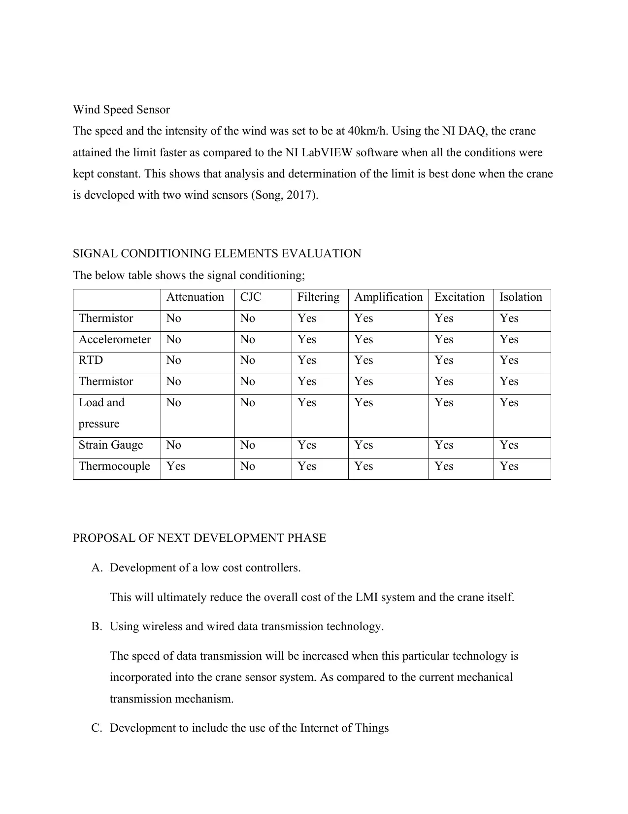
This report provides a detailed analysis of a Crane Load Moment Indicator (LMI) system, focusing on its various components and functionalities. The introduction explains the significance of LMI systems in cranes, emphasizing their role in measuring load values and ensuring safe operation. The report then delves into specific LMI systems, including the load plate system, angle and length transmitter system, angle sensor system, wind speed sensor, and anti-two-block sensor system. A critical analysis section presents experimental evaluations of the anti-two-block sensor and wind speed sensor, using NI LabVIEW and DAQ software. The analysis highlights the importance of accurate measurements and the effectiveness of different software tools. The report concludes with a discussion of the next development phase, including the use of low-cost controllers, wireless data transmission, and the Internet of Things. The references section provides a comprehensive list of sources used in the report. The report is a result of a university assignment, and the solution is available on Desklib.
Document Page
CRANE LMI SYSTEM FOR GLOBAL TECHNOLOGIES
Student Name
Professor’s Name
Date
tabler-icon-diamond-filled.svg

Paraphrase This Document

Need a fresh take? Get an instant paraphrase of this document with our AI Paraphraser
Document Page
Table of Contents
INTRODUCTION TO LMI SYSTEM............................................................................................3
LMI SYSTEMS IN CRANES..........................................................................................................3
Load plate system.........................................................................................................................3
Angle and length transmitter system............................................................................................3
Angle sensor system.....................................................................................................................3
Wind speed sensor........................................................................................................................4
Anti-two Block sensor system......................................................................................................4
LMI SYSTEM FRONT PANEL......................................................................................................4
A MEASUREMENT SYSTEM BLOCK DIAGRAM....................................................................5
EXPERIMENTAL CRITICAL ANALYSIS...................................................................................5
The Anti-Two-Block Sensor System............................................................................................5
Wind Speed Sensor.......................................................................................................................6
SIGNAL CONDITIONING ELEMENTS EVALUATION............................................................6
NEXT DEVELOPMENT PHASE...................................................................................................6
CONCLUSION................................................................................................................................6
References........................................................................................................................................7
Document Page
INTRODUCTION TO LMI SYSTEM
Cranes that are involved in the usage of Loan Moment Indicator are known as hydraulic. The
Loan Moment Indicator in cranes is used in reading the load’s measurement value using
transducers. Pressure is employed in the transducers operation. They as well read the cylinder’s
pressure in the crane’s lift. The significance of the Loan Moment Indicator in cranes is to tell how
loads are lifted (Baohuai & Zhang, 2019). Using this specific mechanism, the load’s operator can
be able to tell the amount of load that the crane is lifting and whether the load that the crane is
lifting has exceeded. In simple terms, the LMI is employed to measure the moment and bear
force in the crane’s arms when its operating.
LMI SYSTEMS IN CRANES
Load plate system
There is employment of the load plate system on cranes that are used in offloading and loading of
loads and goods that are very heavy. These cranes consist of those employed in offloading and
loading coils, tracks, steel mills, steel plates, the ocean vessels and many other loads that too
heavy. The meaning of this word load plate is a space that the load is put as it awaits to be
transferred into a different plate vessel (Bell et al. 2014).
Angle and length transmitter system
This is part of the crane’s LMI system that is used in the measurement of the cylinder’s
telescoping and angle when compared the force of gravity. The use of this transmitter system is
majorly employed by all cranes. When this system is employed, the measurement of boom angle
and the boom length of the crane are assured (Banaś et al. 2014). Although this sensor system
does not resist to some of the environments, places with harsh conditions, particularly to the
mobile cranes that work in different parts of a country where they are carried into, there is
removal of this sensor system.
Angle sensor system
This system is amongst the most important and essential in the Load Moment Indicator crane
system. The work of this sensor system is to ease the measurement of the angle and the position
of the steer wheel that the crane’s operator is using. It can as well be used to show the turning
angle of the steering wheel. There is a scanning tool in this angle sensor that is used to give data
Document Page
about the steering wheel’s general position and that is given in degrees and when it has turned
(Wu & Cai, 2018).
Wind speed sensor
Always, cranes of all types are manufactured and designed that they can’t work in places where
the speed wind is very high and harsh conditions. All this is for the safety of the crane operator
and the crane. This wind speed sensor that is built-in the cranes is used in measurement and to
determine the safety of the area during and before the operation. This crane sensor of wind
usually notifies the operator when there is very high wind speed on the dashboard so that the
operator takes the precautions that are necessary (Shi, Teng & Li, 2016).
Anti-two Block sensor system
The main purpose of this system is to prevent and warn the crane operator from a condition
known as two block that is created in cranes. This two block condition is critically a condition
that is involved when the crane’s hook block on the lower side is lifted highly to the extent of
connecting to the boom hardware’s parts of the crane. This word A2B came from the tackle and
block engineering physics vocabulary which clarifies that when the lower and upper part of the
pulley connect with each other (Barbesi et al. 2017).
A design of a typical LMI system
tabler-icon-diamond-filled.svg

Paraphrase This Document

Need a fresh take? Get an instant paraphrase of this document with our AI Paraphraser
Document Page
A measurement software program (LabVIEW/ C++)
EXPERIMENTAL CRITICAL ANALYSIS
As research stresses that two systems of sensor be critically examined by the use of the NI
LabVIEW software along with the DAQ software, this sensor system of anti-two block and the
sensor of the speed wind were critically evaluated as shown here below.
The Anti-Two-Block Sensor System
This sensor system of anti-two is critically evaluated using NI LabVIEW software besides NI
DAQ software. From the analysis that NI DAQ was used, it was apparent that the space below
which the weight of the boom as well as the hook of the block is actually examined and was
found to be approximately 15 inches from the analysis. That seems to be different from this
critical examination of NI LabVIEW software which the distance limit among the weight of the
boom as well as the crane’s hook block was found to be 5 inches only (Barbesi et al. 2017).
Document Page
Wind Speed Sensor
The speed and the intensity of the wind was set to be at 40km/h. Using the NI DAQ, the crane
attained the limit faster as compared to the NI LabVIEW software when all the conditions were
kept constant. This shows that analysis and determination of the limit is best done when the crane
is developed with two wind sensors (Song, 2017).
SIGNAL CONDITIONING ELEMENTS EVALUATION
The below table shows the signal conditioning;
Attenuation CJC Filtering Amplification Excitation Isolation
Thermistor No No Yes Yes Yes Yes
Accelerometer No No Yes Yes Yes Yes
RTD No No Yes Yes Yes Yes
Thermistor No No Yes Yes Yes Yes
Load and
pressure
No No Yes Yes Yes Yes
Strain Gauge No No Yes Yes Yes Yes
Thermocouple Yes No Yes Yes Yes Yes
PROPOSAL OF NEXT DEVELOPMENT PHASE
A. Development of a low cost controllers.
This will ultimately reduce the overall cost of the LMI system and the crane itself.
B. Using wireless and wired data transmission technology.
The speed of data transmission will be increased when this particular technology is
incorporated into the crane sensor system. As compared to the current mechanical
transmission mechanism.
C. Development to include the use of the Internet of Things
Document Page
This technology will help in remote access of crane dashboard which will enhance
assistance in controlling crane as well as decision making.
CONCLUSION
To finish up, the NI DAQ investigation supposedly is increasingly precise when contrasted with
the NI LabView programming examination. It is in this way suggested NI DAQ investigation be
utilized in see and during the way toward planning and advancement of the crane LMI
framework.
References
Baohuai, W.X.Z. and Zhang, X., 2019. Development of the Measuring and Controlling System of
Heat Exchanger Performance Testing Equipment Based on LabVIEW [J]. Journal of Mechanical
Engineering, 4, p.057.
Bell, I., Falcon, J., Limroth, J. and Robinson, K., 2014, September. Integration of hardware into
the LabVIEW environment for rapid prototyping and the development of control design
applications. In Proc. of the UKACC Control 2004 Mini Symposia (pp. 79-81).
Banaś, W., Herbuś, K., Kost, G., Nierychlok, A., Ociepka, P. and Reclik, D., 2014. Simulation of
the Stewart platform carried out using the Siemens NX and NI LabVIEW programs. In Advanced
Materials Research (Vol. 837, pp. 537-542). Trans Tech Publications Ltd.
Wu, B. and Cai, C., 2018. Hydraulic monitoring system based on LabVIEW. In 2008 Second
International Symposium on Intelligent Information Technology Application (Vol. 2, pp. 254-
258). IEEE.
Barbesi, D., Vilas, V.V., Millet, S., Sandow, M., Colle, J.Y. and de las Heras, L.A., 2017. A
LabVIEW®-based software for the control of the AUTORAD platform: a fully automated
multisequential flow injection analysis Lab-on-Valve (MSFIA-LOV) system for radiochemical
analysis. Journal of radioanalytical and nuclear chemistry, 313(1), pp.217-227.
Song, R., 2017, February. Research on Testing System of Asynchronous Motor Based on
LabVIEW. In 2016 2nd International Conference on Materials Engineering and Information
Technology Applications (MEITA 2016). Atlantis Press.
tabler-icon-diamond-filled.svg

Paraphrase This Document

Need a fresh take? Get an instant paraphrase of this document with our AI Paraphraser
Document Page
Shi, C., Teng, G. and Li, Z., 2016. An approach of pig weight estimation using binocular stereo
system based on LabVIEW. Computers and Electronics in Agriculture, 129, pp.37-43.
chevron_up_icon
1 out of 8
circle_padding
hide_on_mobile
zoom_out_icon
[object Object]