Coursework on Creep and Fatigue in Advanced Solid Mechanics (ENGT5258)
VerifiedAdded on 2023/05/30
|19
|2327
|493
Homework Assignment
AI Summary
This assignment delves into the principles of advanced solid mechanics, focusing on creep and fatigue phenomena. It begins with an exploration of stress relaxation and creep rupture strength, including factors influencing creep behavior. The assignment presents calculations and analyses related to creep and fatigue, including the application of Miner's rule for cumulative fatigue damage. It explores various fatigue life methods like nominal stress-life, local strain-life, and fatigue crack growth methods. The document also covers the concept of endurance limits, stress concentration, and notch sensitivity, providing detailed explanations and equations. Furthermore, the assignment analyzes stress concentrations, fatigue limits, and the impact of stress ratios. The document concludes with calculations and derivations demonstrating the application of the concepts discussed throughout the assignment. The solution is comprehensive, providing a thorough understanding of creep and fatigue in solid mechanics.
Advanced Solid Mechanics 1
ADVANCE SOLID MECHANICS
By Name
Course
Instructor
Institution
Location
Date
ADVANCE SOLID MECHANICS
By Name
Course
Instructor
Institution
Location
Date
Paraphrase This Document
Need a fresh take? Get an instant paraphrase of this document with our AI Paraphraser
Advanced Solid Mechanics 2
QUESTION ONE
Part 1 Stress relaxation
This is reduction in stress which can be observed with accordance to the quantity of deflection
produced in the structure. It is usually true since maintaining a material in a deformed position
for some period of time leads to plastic deformation1. Creep is an increased plastic deformation
in a constant force applied.
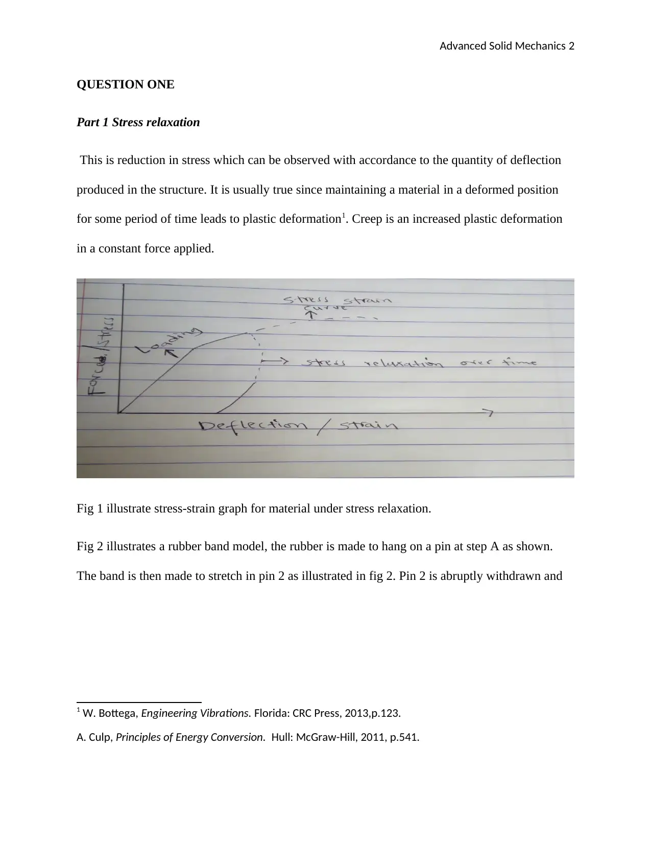
Fig 1 illustrate stress-strain graph for material under stress relaxation.
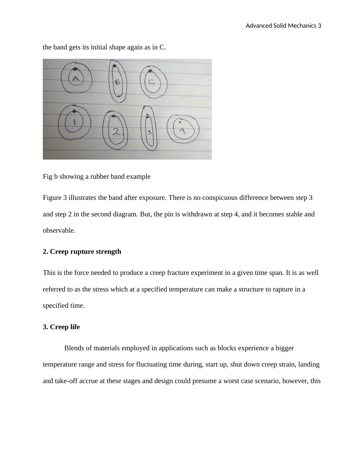
Fig 2 illustrates a rubber band model, the rubber is made to hang on a pin at step A as shown.
The band is then made to stretch in pin 2 as illustrated in fig 2. Pin 2 is abruptly withdrawn and
1 W. Bottega, Engineering Vibrations. Florida: CRC Press, 2013,p.123.
A. Culp, Principles of Energy Conversion. Hull: McGraw-Hill, 2011, p.541.
Advanced Solid Mechanics 3
the band gets its initial shape again as in C.
Fig b showing a rubber band example
Figure 3 illustrates the band after exposure. There is no conspicuous difference between step 3
and step 2 in the second diagram. But, the pin is withdrawn at step 4, and it becomes stable and
observable.
2. Creep rupture strength
This is the force needed to produce a creep fracture experiment in a given time span. It is as well
referred to as the stress which at a specified temperature can make a structure to rapture in a
specified time.
3. Creep life
Blends of materials employed in applications such as blocks experience a bigger
temperature range and stress for fluctuating time during, start up, shut down creep strain, landing
and take-off accrue at these stages and design could presume a worst case scenario, however, this
⊘ This is a preview!⊘
Do you want full access?
Subscribe today to unlock all pages.

Trusted by 1+ million students worldwide
Advanced Solid Mechanics 4
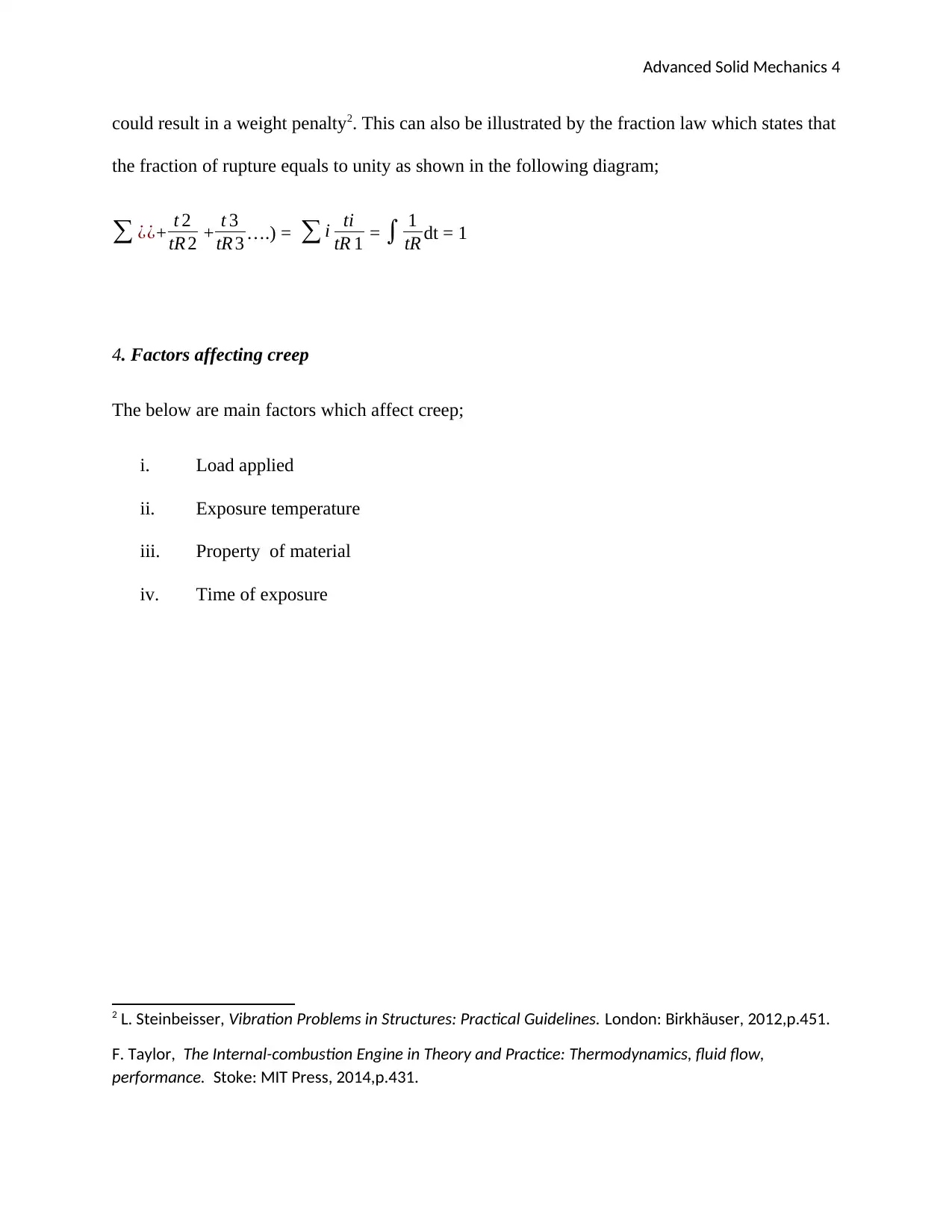
could result in a weight penalty2. This can also be illustrated by the fraction law which states that
the fraction of rupture equals to unity as shown in the following diagram;
∑ ¿¿+ t 2
tR 2 + t 3
tR 3 ….) = ∑ i ti
tR 1 = ∫ 1
tR dt = 1
4. Factors affecting creep
The below are main factors which affect creep;
i. Load applied
ii. Exposure temperature
iii. Property of material
iv. Time of exposure
2 L. Steinbeisser, Vibration Problems in Structures: Practical Guidelines. London: Birkhäuser, 2012,p.451.
F. Taylor, The Internal-combustion Engine in Theory and Practice: Thermodynamics, fluid flow,
performance. Stoke: MIT Press, 2014,p.431.
Paraphrase This Document
Need a fresh take? Get an instant paraphrase of this document with our AI Paraphraser
Advanced Solid Mechanics 5
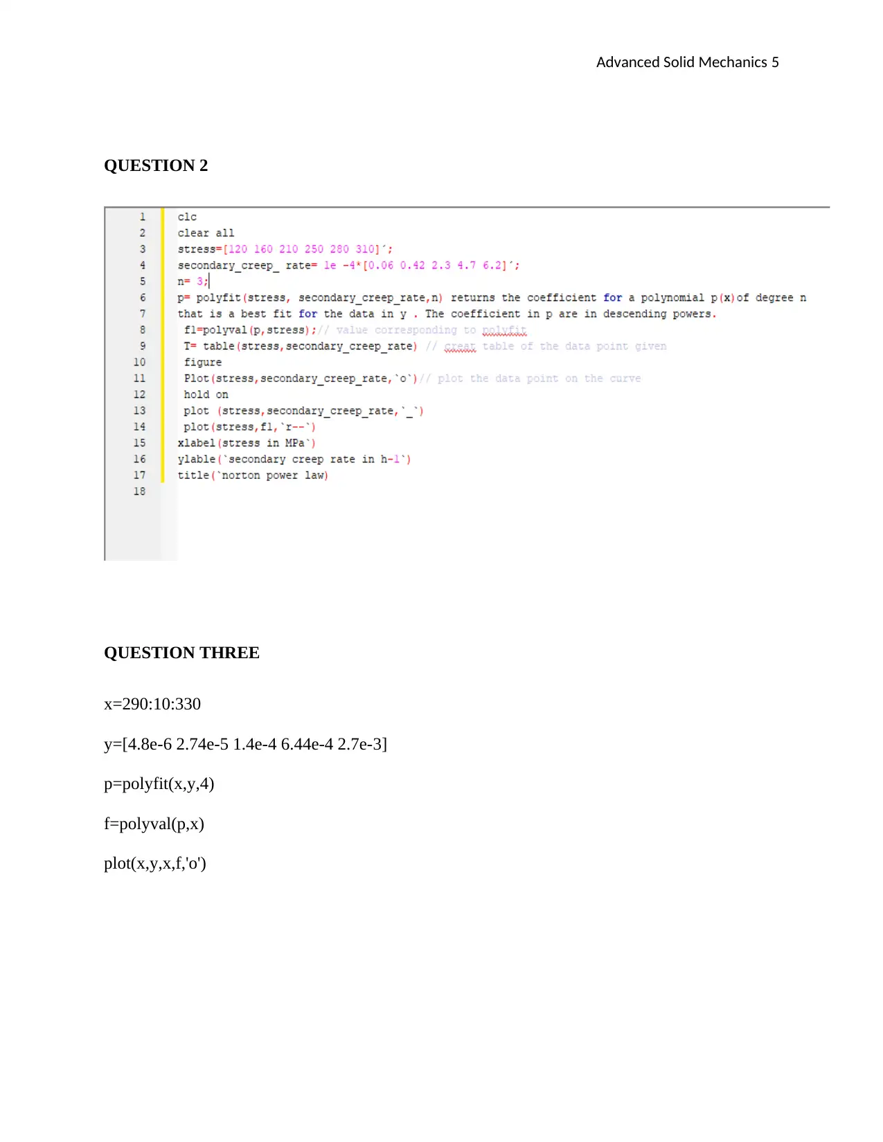
QUESTION 2
QUESTION THREE
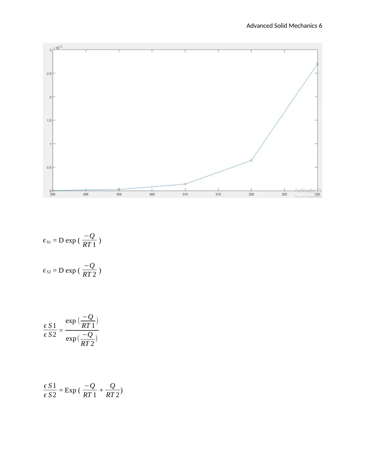
x=290:10:330
y=[4.8e-6 2.74e-5 1.4e-4 6.44e-4 2.7e-3]
p=polyfit(x,y,4)
f=polyval(p,x)
plot(x,y,x,f,'o')
QUESTION 2
QUESTION THREE
x=290:10:330
y=[4.8e-6 2.74e-5 1.4e-4 6.44e-4 2.7e-3]
p=polyfit(x,y,4)
f=polyval(p,x)
plot(x,y,x,f,'o')
Advanced Solid Mechanics 6
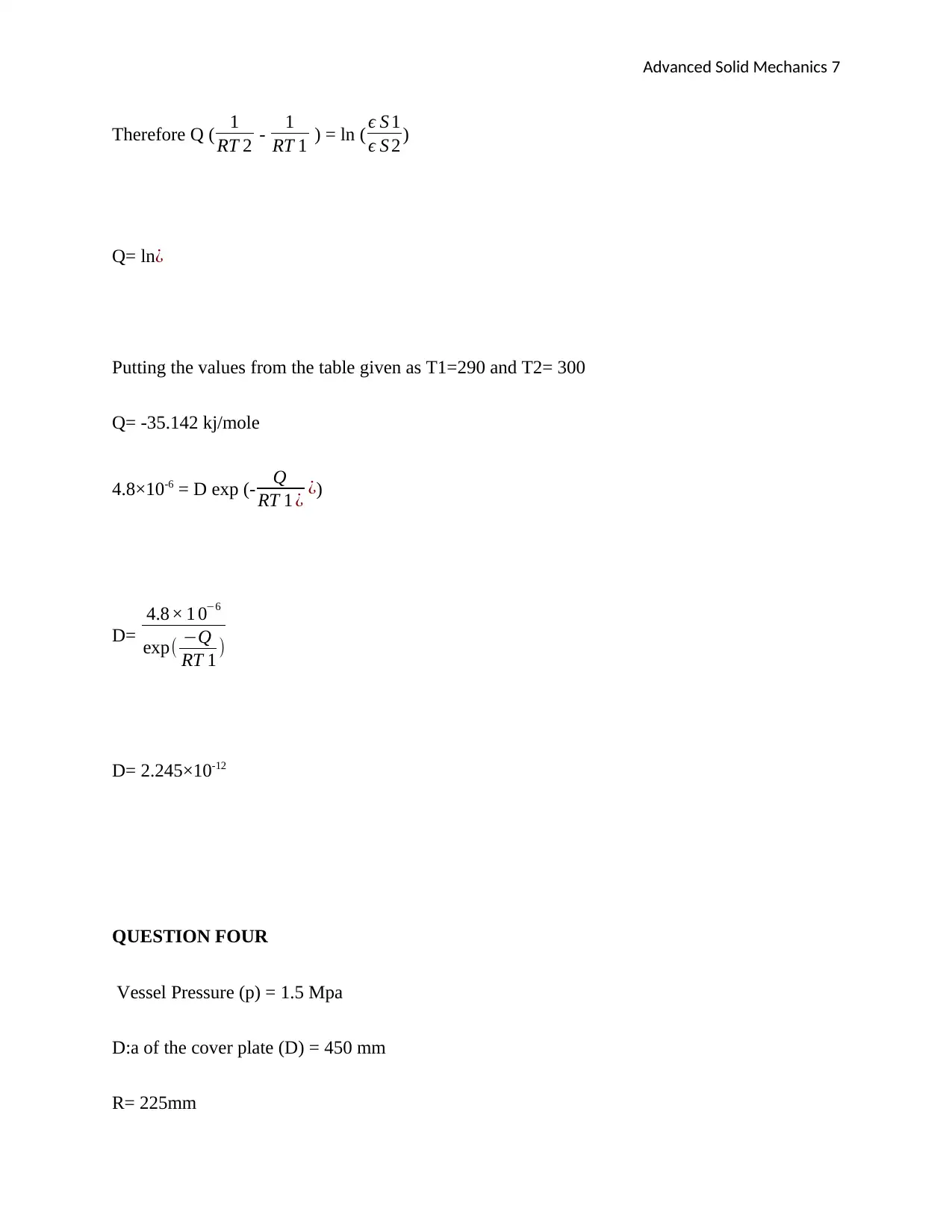
ϵ S1 = D exp ( −Q
RT 1 )
ϵ S2 = D exp ( −Q
RT 2 )
ϵ S 1
ϵ S 2 =
exp ( −Q
RT 1 )
exp ( −Q
RT 2 )
ϵ S 1
ϵ S 2 = Exp ( −Q
RT 1 + Q
RT 2 )
ϵ S1 = D exp ( −Q
RT 1 )
ϵ S2 = D exp ( −Q
RT 2 )
ϵ S 1
ϵ S 2 =
exp ( −Q
RT 1 )
exp ( −Q
RT 2 )
ϵ S 1
ϵ S 2 = Exp ( −Q
RT 1 + Q
RT 2 )
⊘ This is a preview!⊘
Do you want full access?
Subscribe today to unlock all pages.

Trusted by 1+ million students worldwide
Advanced Solid Mechanics 7
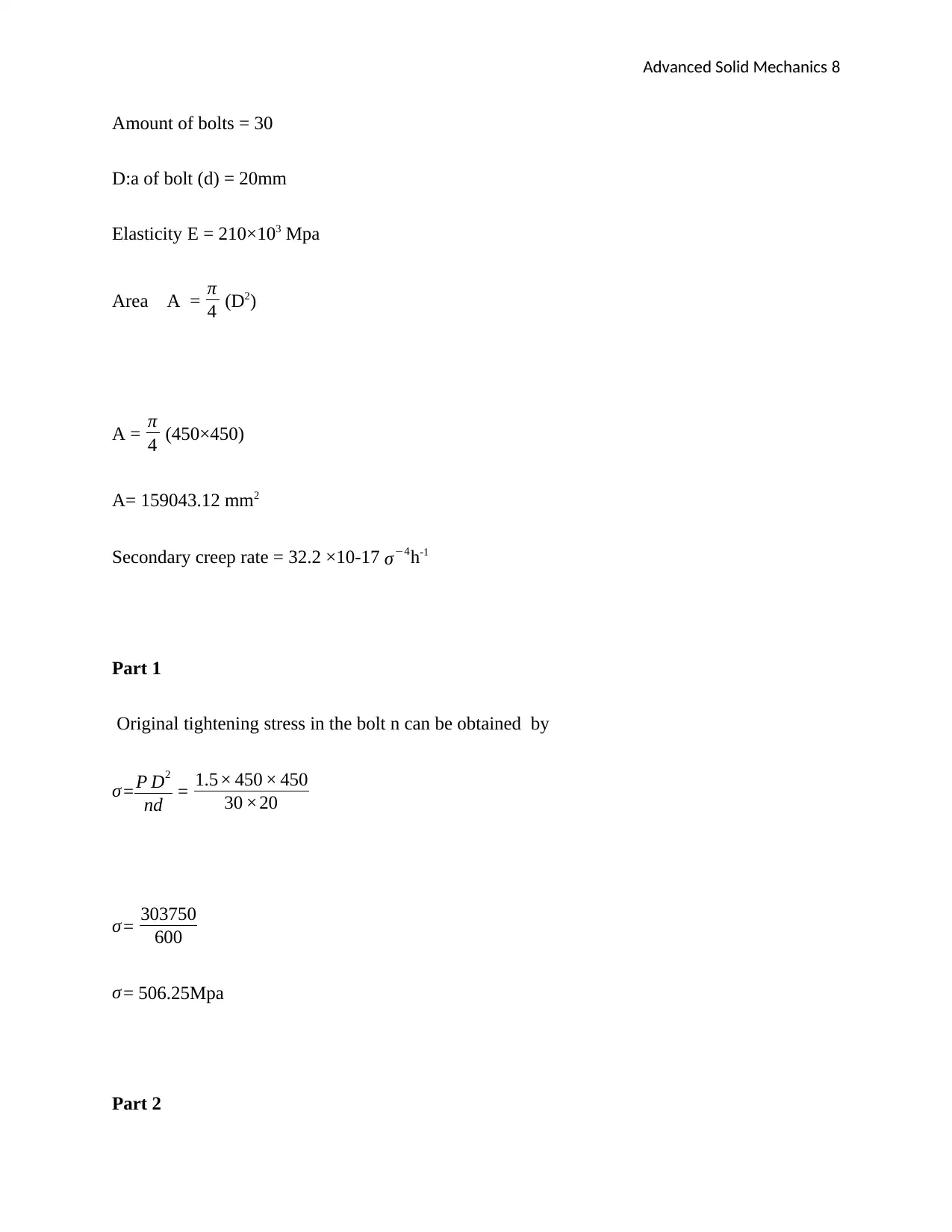
Therefore Q ( 1
RT 2 - 1
RT 1 ) = ln ( ϵ S 1
ϵ S 2 )
Q= ln¿
Putting the values from the table given as T1=290 and T2= 300
Q= -35.142 kj/mole
4.8×10-6 = D exp (- Q
RT 1 ¿ ¿)
D=
4.8× 1 0−6
exp( −Q
RT 1 )
D= 2.245×10⁻¹²
QUESTION FOUR
Vessel Pressure (p) = 1.5 Mpa
D:a of the cover plate (D) = 450 mm
R= 225mm
Paraphrase This Document
Need a fresh take? Get an instant paraphrase of this document with our AI Paraphraser
Advanced Solid Mechanics 8
Amount of bolts = 30
D:a of bolt (d) = 20mm
Elasticity E = 210×103 Mpa
Area A = π
4 (D2)
A = π
4 (450×450)
A= 159043.12 mm2
Secondary creep rate = 32.2 ×10⁻¹⁷ σ−4h-1
Part 1
Original tightening stress in the bolt n can be obtained by
σ = P D2
nd = 1.5× 450 × 450
30 ×20
σ = 303750
600
σ = 506.25Mpa
Part 2
Advanced Solid Mechanics 9
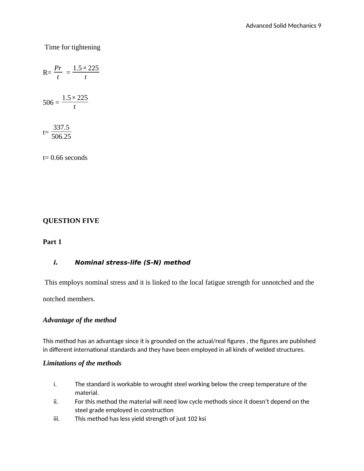
Time for tightening
R= Pr
t = 1.5× 225
t
506 = 1.5× 225
t
t= 337.5
506.25
t= 0.66 seconds
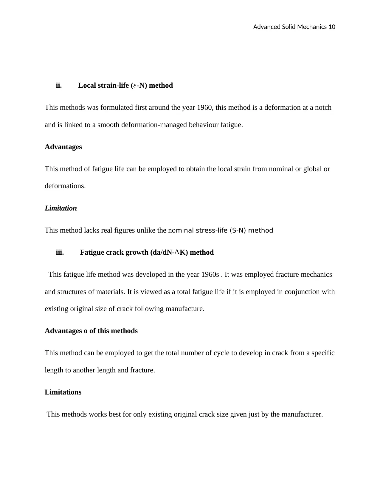
QUESTION FIVE
Part 1
i. Nominal stress-life (S-N) method
This employs nominal stress and it is linked to the local fatigue strength for unnotched and the
notched members.
Advantage of the method
This method has an advantage since it is grounded on the actual/real figures , the figures are published
in different international standards and they have been employed in all kinds of welded structures.
Limitations of the methods
i. The standard is workable to wrought steel working below the creep temperature of the
material.
ii. For this method the material will need low cycle methods since it doesn’t depend on the
steel grade employed in construction
iii. This method has less yield strength of just 102 ksi
⊘ This is a preview!⊘
Do you want full access?
Subscribe today to unlock all pages.

Trusted by 1+ million students worldwide
Advanced Solid Mechanics 10
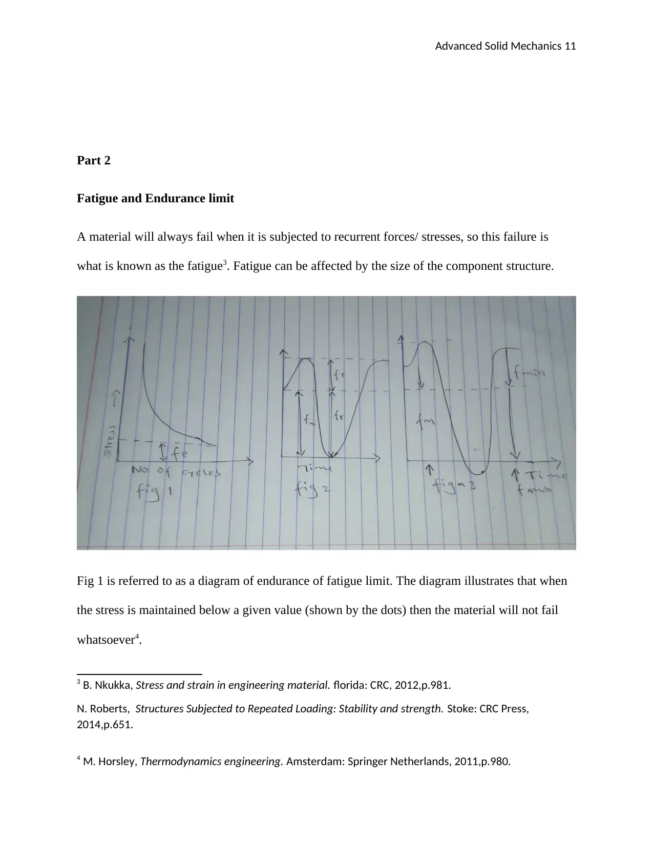
ii. Local strain-life ( ε-N) method
This methods was formulated first around the year 1960, this method is a deformation at a notch
and is linked to a smooth deformation-managed behaviour fatigue.
Advantages
This method of fatigue life can be employed to obtain the local strain from nominal or global or
deformations.
Limitation
This method lacks real figures unlike the nominal stress-life (S-N) method
iii. Fatigue crack growth (da/dN-∆K) method
This fatigue life method was developed in the year 1960s . It was employed fracture mechanics
and structures of materials. It is viewed as a total fatigue life if it is employed in conjunction with
existing original size of crack following manufacture.
Advantages o of this methods
This method can be employed to get the total number of cycle to develop in crack from a specific
length to another length and fracture.
Limitations
This methods works best for only existing original crack size given just by the manufacturer.
Paraphrase This Document
Need a fresh take? Get an instant paraphrase of this document with our AI Paraphraser
Advanced Solid Mechanics 11
Part 2
Fatigue and Endurance limit
A material will always fail when it is subjected to recurrent forces/ stresses, so this failure is
what is known as the fatigue3. Fatigue can be affected by the size of the component structure.
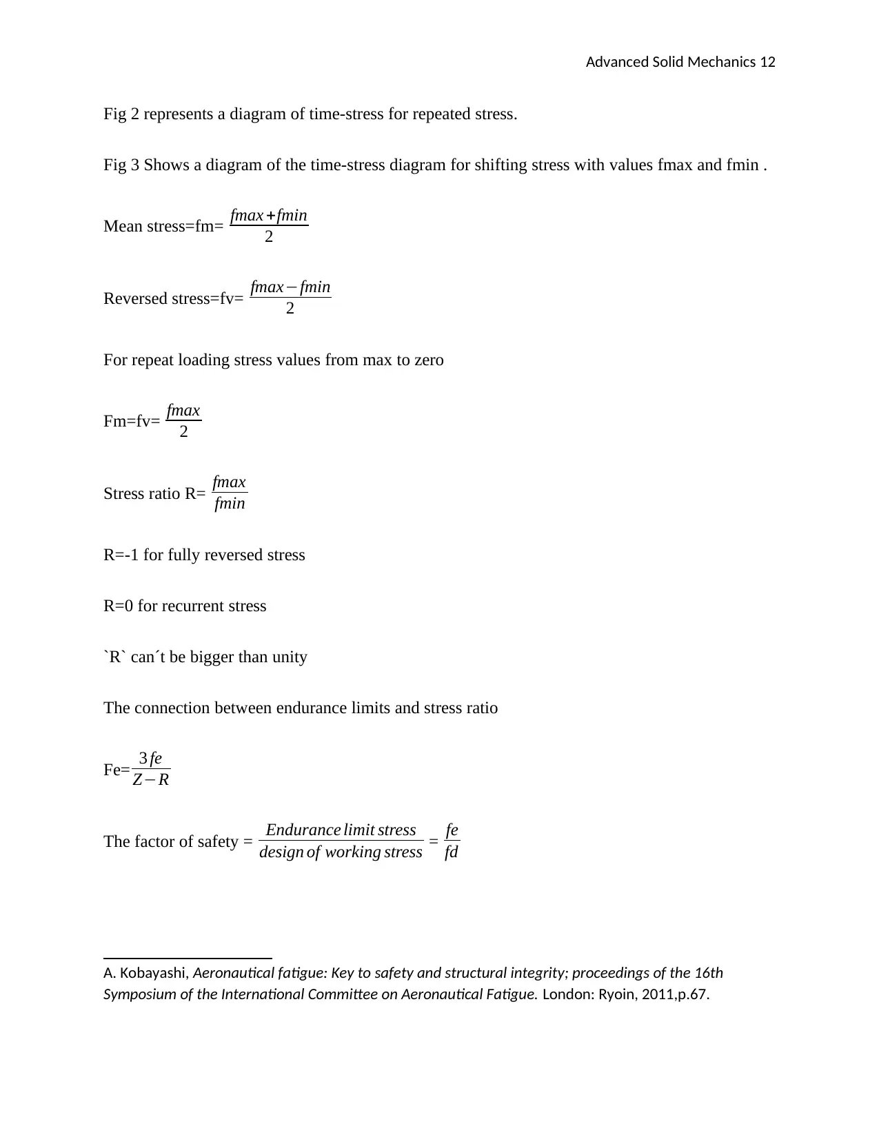
Fig 1 is referred to as a diagram of endurance of fatigue limit. The diagram illustrates that when
the stress is maintained below a given value (shown by the dots) then the material will not fail
whatsoever4.
3 B. Nkukka, Stress and strain in engineering material. florida: CRC, 2012,p.981.
N. Roberts, Structures Subjected to Repeated Loading: Stability and strength. Stoke: CRC Press,
2014,p.651.
4 M. Horsley, Thermodynamics engineering. Amsterdam: Springer Netherlands, 2011,p.980.
Advanced Solid Mechanics 12
Fig 2 represents a diagram of time-stress for repeated stress.
Fig 3 Shows a diagram of the time-stress diagram for shifting stress with values fmax and fmin .
Mean stress=fm= fmax +fmin
2
Reversed stress=fv= fmax−fmin
2
For repeat loading stress values from max to zero
Fm=fv= fmax
2
Stress ratio R= fmax
fmin
R=-1 for fully reversed stress
R=0 for recurrent stress
`R` can´t be bigger than unity
The connection between endurance limits and stress ratio
Fe= 3 fe
Z−R
The factor of safety = Endurance limit stress
design of working stress = fe
fd
A. Kobayashi, Aeronautical fatigue: Key to safety and structural integrity; proceedings of the 16th
Symposium of the International Committee on Aeronautical Fatigue. London: Ryoin, 2011,p.67.
⊘ This is a preview!⊘
Do you want full access?
Subscribe today to unlock all pages.

Trusted by 1+ million students worldwide
1 out of 19
Your All-in-One AI-Powered Toolkit for Academic Success.
+13062052269
info@desklib.com
Available 24*7 on WhatsApp / Email
![[object Object]](/_next/static/media/star-bottom.7253800d.svg)
Unlock your academic potential
Copyright © 2020–2026 A2Z Services. All Rights Reserved. Developed and managed by ZUCOL.
