Analysis of Creep and Fatigue in Materials: A Detailed Report
VerifiedAdded on 2020/04/13
|16
|2305
|312
Report
AI Summary
This report provides a detailed analysis of creep and fatigue phenomena in materials. It begins with an introduction to creep, including stress relaxation, creep rupture strength, and creep life, and provides practical examples. The report then delves into the factors affecting creep and includes calculations using the Norton power law and Arrhenius definition. The report also explores fatigue, discussing fatigue life methods, endurance limits, stress concentration, and notch sensitivity. It provides examples and calculations, including the application of Miner's rule and predictions based on Gerber, Goodman, and Soderberg methods. The analysis covers material failure predictions, and the report includes MATLAB polyfit analyses for creep rate determination and related calculations. The report concludes with a summary of the key findings and a comprehensive bibliography.
Creep and Fatigue 1
CREEP AND FATIGUE
A Research Paper on Creep and Fatigue By
Student’s Name
Name of the Professor
Institutional Affiliation
City/State
Year/Month/Day
CREEP AND FATIGUE
A Research Paper on Creep and Fatigue By
Student’s Name
Name of the Professor
Institutional Affiliation
City/State
Year/Month/Day
Paraphrase This Document
Need a fresh take? Get an instant paraphrase of this document with our AI Paraphraser
Creep and Fatigue 2
INTRODUCTION
Creep is a term used in referring to a process of progressive deformation of a material
at a stress that is constant. Fatigue refers to the process of deformation of a material at
repetitive stress. The interaction between creep and stress refers to the deformation of a
material under stresses that are repetitive at high temperatures. Fatigue and creep are the
phenomenon that leads to deformation and ultimately failure of the material.
CREEP
1. Explain and discuss the following phenomena creep with practical examples
i. Stress relaxation
Stress relaxation is the decrease in stress in response to the same amount of strain generated
in the structure. This is basically due keeping the structure is a strained condition for the same
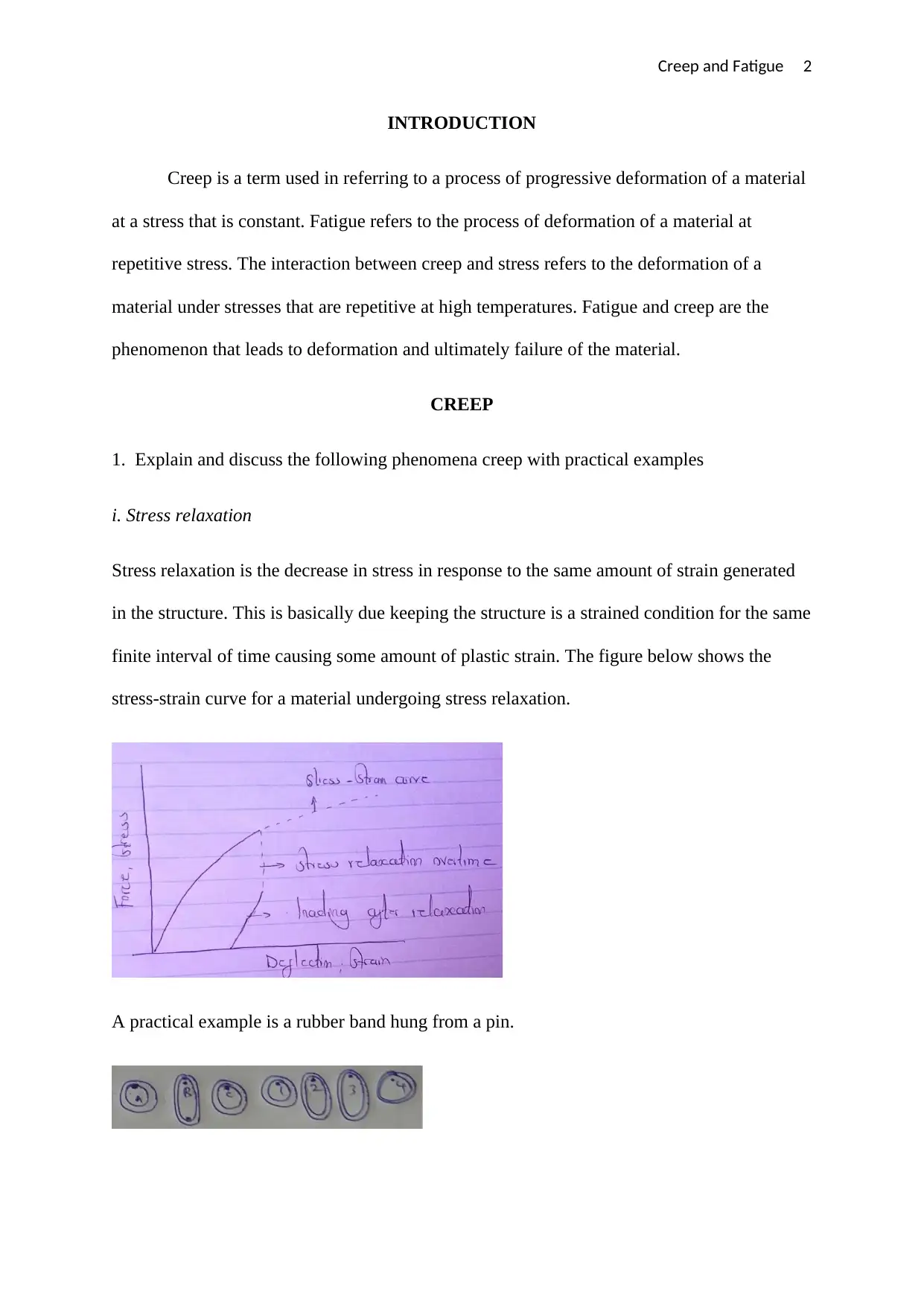
finite interval of time causing some amount of plastic strain. The figure below shows the
stress-strain curve for a material undergoing stress relaxation.
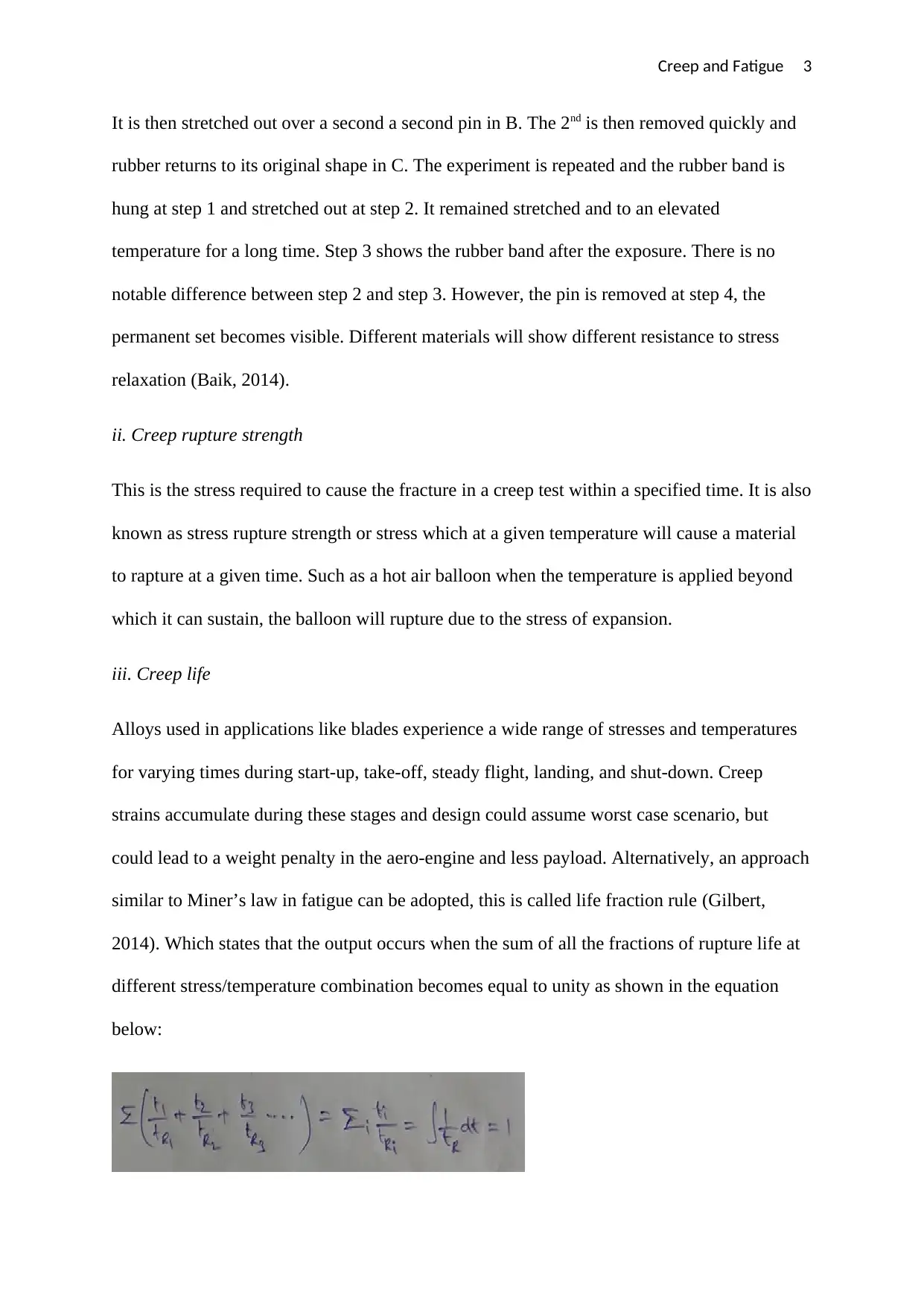
A practical example is a rubber band hung from a pin.
Creep and Fatigue 3
It is then stretched out over a second a second pin in B. The 2nd is then removed quickly and
rubber returns to its original shape in C. The experiment is repeated and the rubber band is
hung at step 1 and stretched out at step 2. It remained stretched and to an elevated
temperature for a long time. Step 3 shows the rubber band after the exposure. There is no
notable difference between step 2 and step 3. However, the pin is removed at step 4, the
permanent set becomes visible. Different materials will show different resistance to stress
relaxation (Baik, 2014).
ii. Creep rupture strength
This is the stress required to cause the fracture in a creep test within a specified time. It is also
known as stress rupture strength or stress which at a given temperature will cause a material
to rapture at a given time. Such as a hot air balloon when the temperature is applied beyond
which it can sustain, the balloon will rupture due to the stress of expansion.
iii. Creep life
Alloys used in applications like blades experience a wide range of stresses and temperatures
for varying times during start-up, take-off, steady flight, landing, and shut-down. Creep
strains accumulate during these stages and design could assume worst case scenario, but
could lead to a weight penalty in the aero-engine and less payload. Alternatively, an approach
similar to Miner’s law in fatigue can be adopted, this is called life fraction rule (Gilbert,
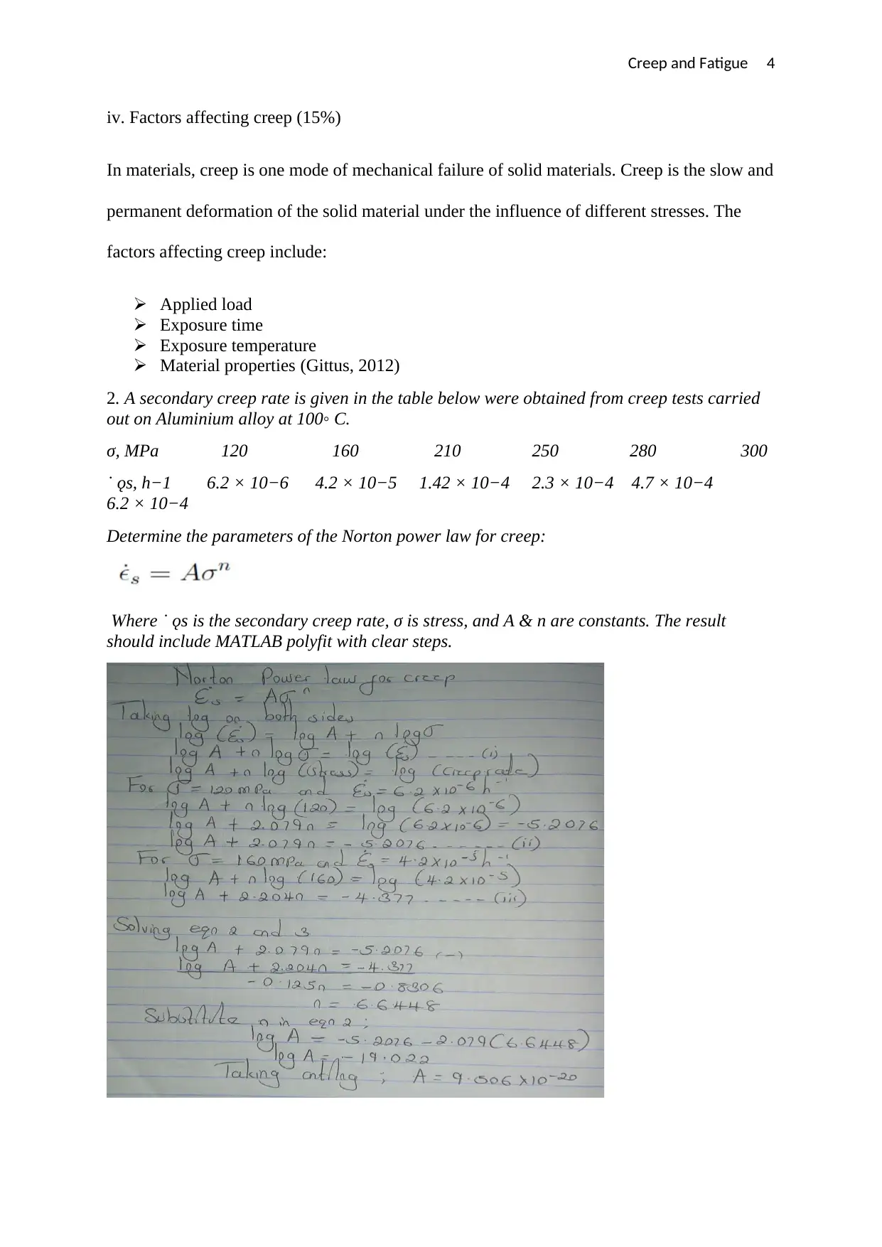
2014). Which states that the output occurs when the sum of all the fractions of rupture life at
different stress/temperature combination becomes equal to unity as shown in the equation
below:
⊘ This is a preview!⊘
Do you want full access?
Subscribe today to unlock all pages.

Trusted by 1+ million students worldwide
Creep and Fatigue 4
iv. Factors affecting creep (15%)
In materials, creep is one mode of mechanical failure of solid materials. Creep is the slow and
permanent deformation of the solid material under the influence of different stresses. The
factors affecting creep include:
Applied load
Exposure time
Exposure temperature
Material properties (Gittus, 2012)
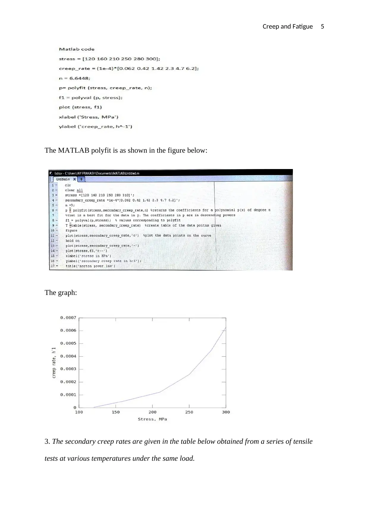
2. A secondary creep rate is given in the table below were obtained from creep tests carried
out on Aluminium alloy at 100◦ C.
σ, MPa 120 160 210 250 280 300
˙ ǫs, h−1 6.2 × 10⁻⁶ 4.2 × 10⁻⁵ 1.42 × 10⁻⁴ 2.3 × 10⁻⁴ 4.7 × 10⁻⁴
6.2 × 10⁻⁴
Determine the parameters of the Norton power law for creep:
Where ˙ ǫs is the secondary creep rate, σ is stress, and A & n are constants. The result
should include MATLAB polyfit with clear steps.
Paraphrase This Document
Need a fresh take? Get an instant paraphrase of this document with our AI Paraphraser
Creep and Fatigue 5
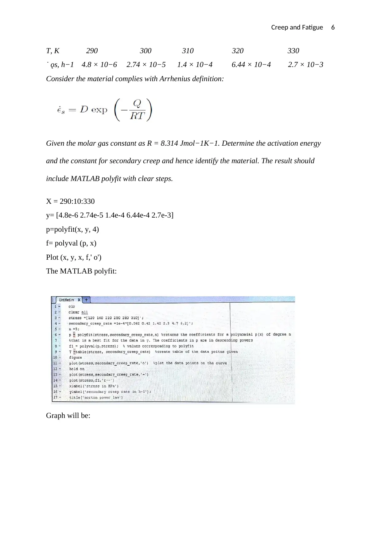
The MATLAB polyfit is as shown in the figure below:
The graph:
3. The secondary creep rates are given in the table below obtained from a series of tensile
tests at various temperatures under the same load.
The MATLAB polyfit is as shown in the figure below:
The graph:
3. The secondary creep rates are given in the table below obtained from a series of tensile
tests at various temperatures under the same load.
Creep and Fatigue 6
T, K 290 300 310 320 330
˙ ǫs, h−1 4.8 × 10⁻⁶ 2.74 × 10⁻⁵ 1.4 × 10⁻⁴ 6.44 × 10⁻⁴ 2.7 × 10⁻³
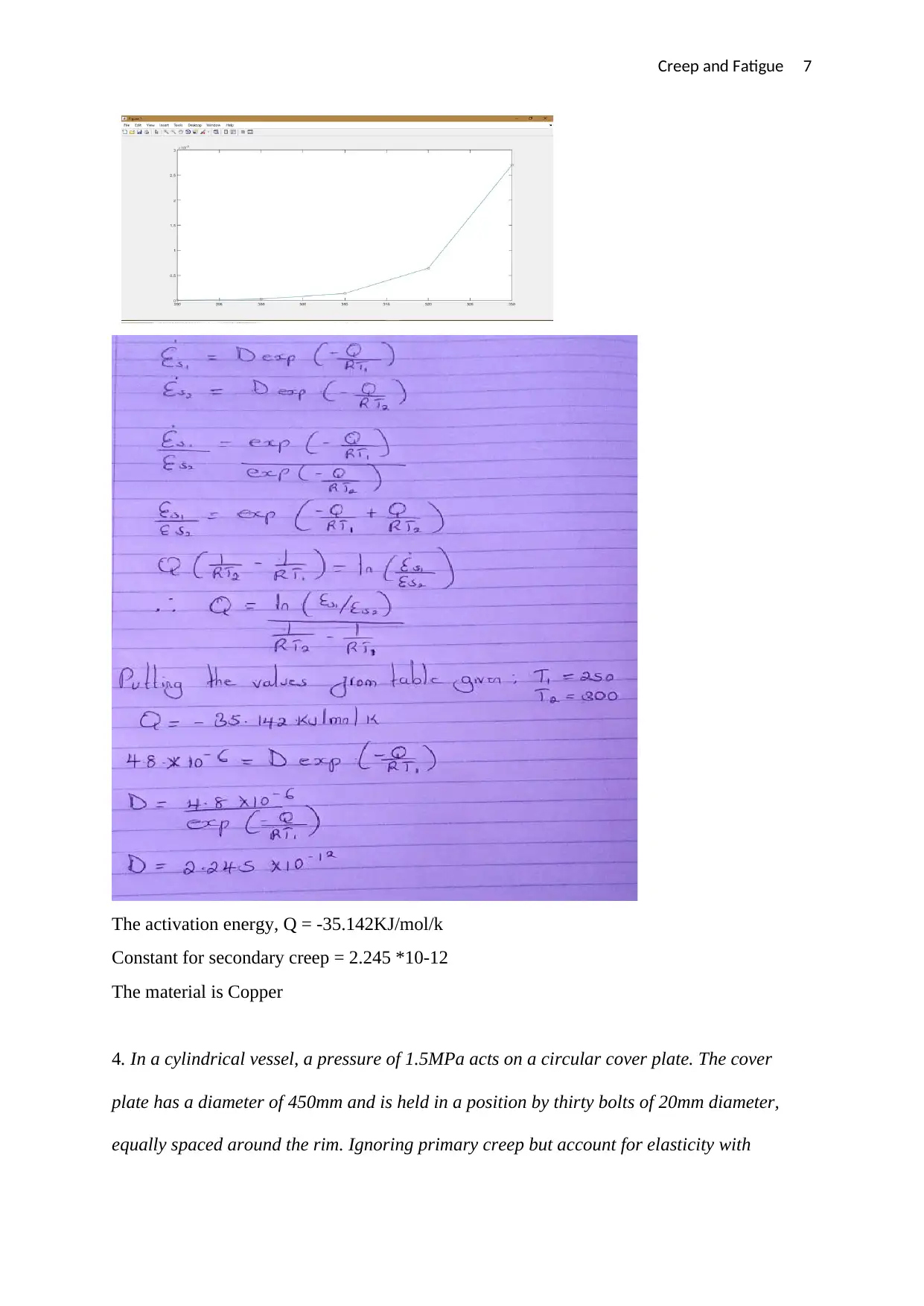
Consider the material complies with Arrhenius definition:
Given the molar gas constant as R = 8.314 Jmol−1K−1. Determine the activation energy
and the constant for secondary creep and hence identify the material. The result should
include MATLAB polyfit with clear steps.
X = 290:10:330
y= [4.8e-6 2.74e-5 1.4e-4 6.44e-4 2.7e-3]
p=polyfit(x, y, 4)
f= polyval (p, x)
Plot (x, y, x, f,' o')
The MATLAB polyfit:
Graph will be:
⊘ This is a preview!⊘
Do you want full access?
Subscribe today to unlock all pages.

Trusted by 1+ million students worldwide
Creep and Fatigue 7
The activation energy, Q = -35.142KJ/mol/k
Constant for secondary creep = 2.245 *10-12
The material is Copper
4. In a cylindrical vessel, a pressure of 1.5MPa acts on a circular cover plate. The cover
plate has a diameter of 450mm and is held in a position by thirty bolts of 20mm diameter,
equally spaced around the rim. Ignoring primary creep but account for elasticity with
Paraphrase This Document
Need a fresh take? Get an instant paraphrase of this document with our AI Paraphraser
Creep and Fatigue 8
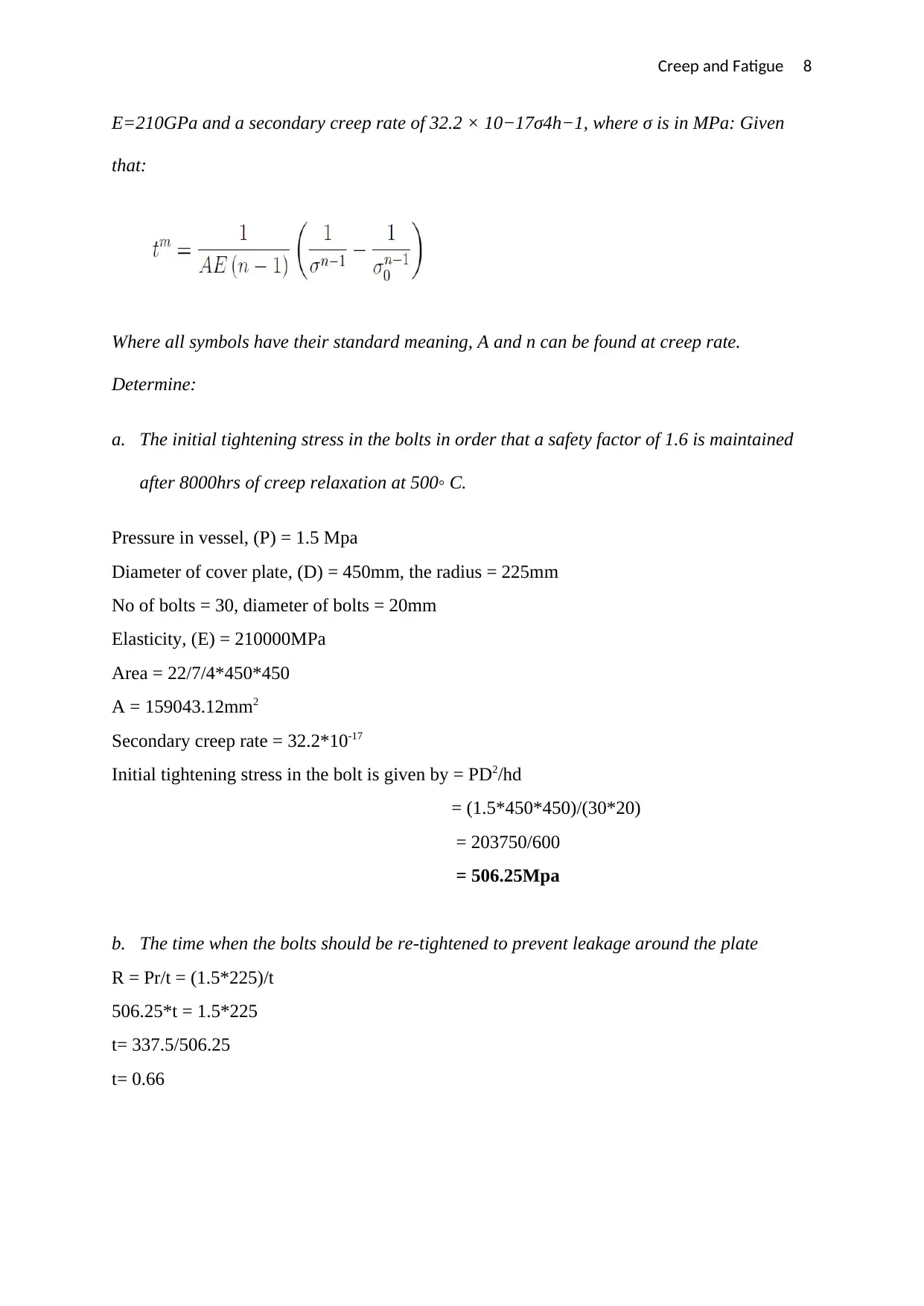
E=210GPa and a secondary creep rate of 32.2 × 10⁻¹⁷σ4h−1, where σ is in MPa: Given
that:
Where all symbols have their standard meaning, A and n can be found at creep rate.
Determine:
a. The initial tightening stress in the bolts in order that a safety factor of 1.6 is maintained
after 8000hrs of creep relaxation at 500◦ C.
Pressure in vessel, (P) = 1.5 Mpa
Diameter of cover plate, (D) = 450mm, the radius = 225mm
No of bolts = 30, diameter of bolts = 20mm
Elasticity, (E) = 210000MPa
Area = 22/7/4*450*450
A = 159043.12mm2
Secondary creep rate = 32.2*10-17
Initial tightening stress in the bolt is given by = PD2/hd
= (1.5*450*450)/(30*20)
= 203750/600
= 506.25Mpa
b. The time when the bolts should be re-tightened to prevent leakage around the plate
R = Pr/t = (1.5*225)/t
506.25*t = 1.5*225
t= 337.5/506.25
t= 0.66
Creep and Fatigue 9
FATIGUE
Give a brief description on the following:
1. Explain the three major fatigue life methods and their benefit and limitations.
When a material is subjected to repeated stresses, it fails at the stress below the yield point
stresses. This type of failure is known as fatigue. The failure is caused by means of
progressive crack formation which are normally fine and microscopic size. The failure of
material is affected by the size. The fatigue of material is affected by the size of the
component, relative magnitude of static and fracturing load and the number of loads reversals
(James, 2013).
2. Discuss endurance limit with practical examples, also include endurance limit
modifying factors.
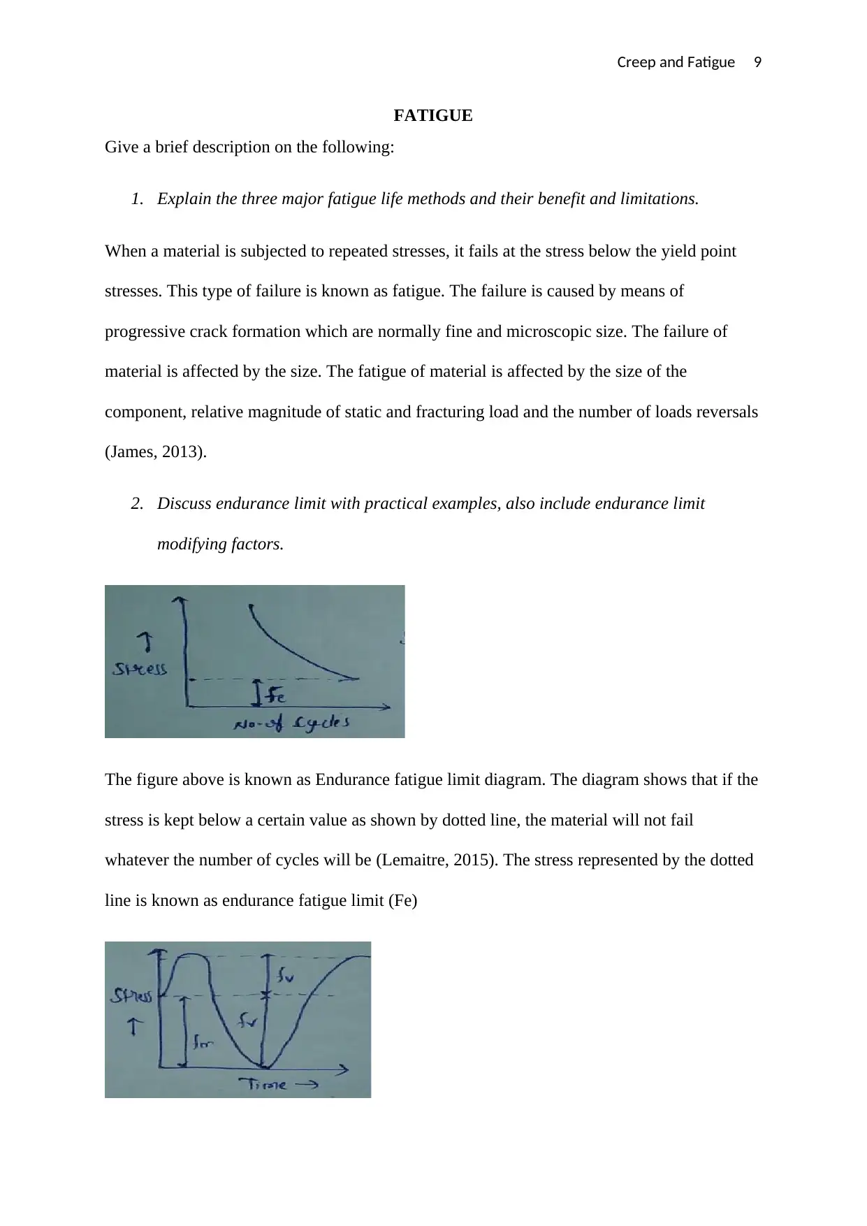
The figure above is known as Endurance fatigue limit diagram. The diagram shows that if the
stress is kept below a certain value as shown by dotted line, the material will not fail
whatever the number of cycles will be (Lemaitre, 2015). The stress represented by the dotted
line is known as endurance fatigue limit (Fe)
⊘ This is a preview!⊘
Do you want full access?
Subscribe today to unlock all pages.

Trusted by 1+ million students worldwide
Creep and Fatigue 10
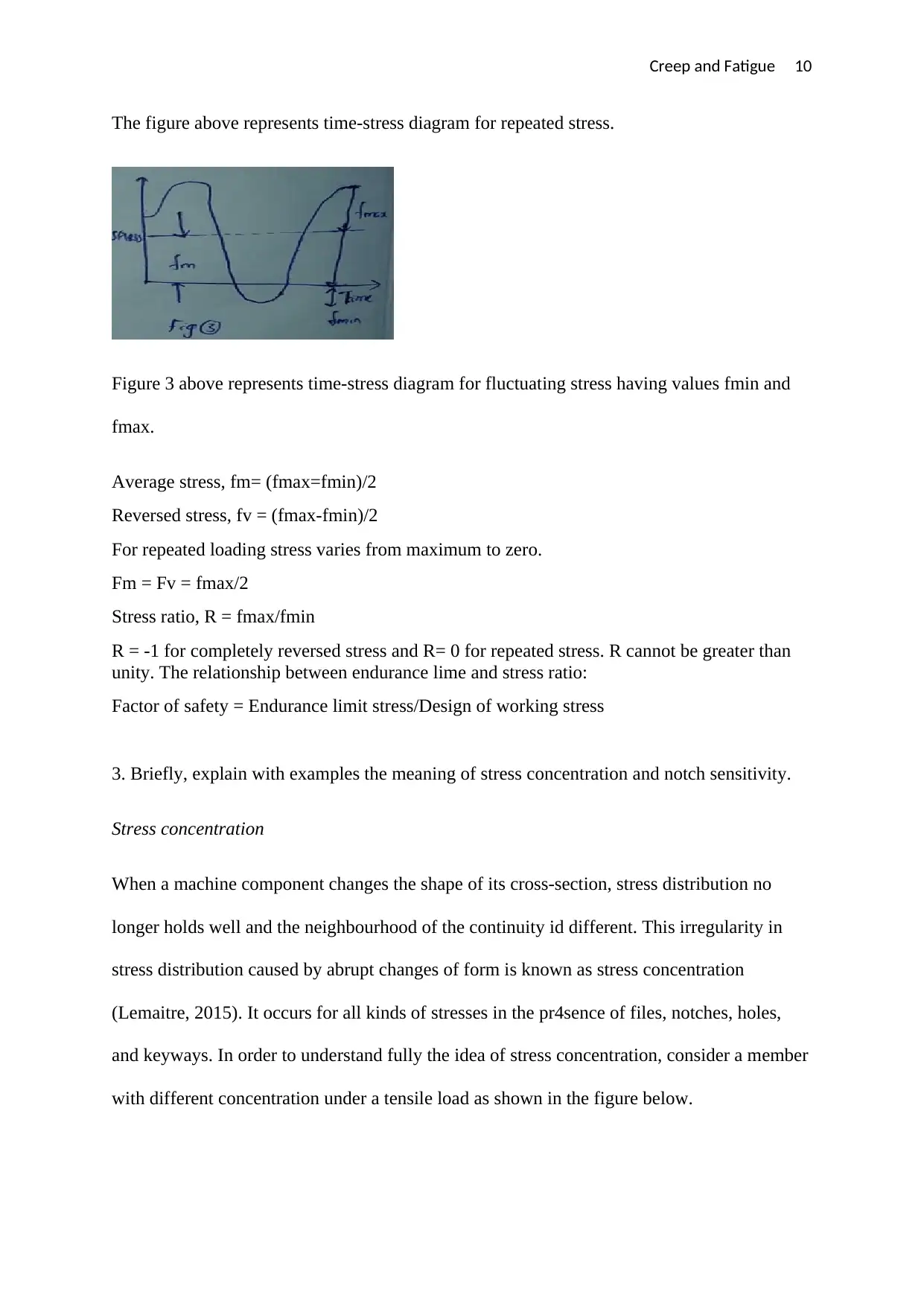
The figure above represents time-stress diagram for repeated stress.
Figure 3 above represents time-stress diagram for fluctuating stress having values fmin and
fmax.
Average stress, fm= (fmax=fmin)/2
Reversed stress, fv = (fmax-fmin)/2
For repeated loading stress varies from maximum to zero.
Fm = Fv = fmax/2
Stress ratio, R = fmax/fmin
R = -1 for completely reversed stress and R= 0 for repeated stress. R cannot be greater than
unity. The relationship between endurance lime and stress ratio:
Factor of safety = Endurance limit stress/Design of working stress
3. Briefly, explain with examples the meaning of stress concentration and notch sensitivity.
Stress concentration
When a machine component changes the shape of its cross-section, stress distribution no
longer holds well and the neighbourhood of the continuity id different. This irregularity in
stress distribution caused by abrupt changes of form is known as stress concentration
(Lemaitre, 2015). It occurs for all kinds of stresses in the pr4sence of files, notches, holes,
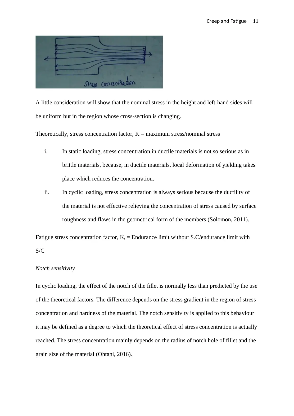
and keyways. In order to understand fully the idea of stress concentration, consider a member
with different concentration under a tensile load as shown in the figure below.
Paraphrase This Document
Need a fresh take? Get an instant paraphrase of this document with our AI Paraphraser
Creep and Fatigue 11
A little consideration will show that the nominal stress in the height and left-hand sides will
be uniform but in the region whose cross-section is changing.
Theoretically, stress concentration factor, K = maximum stress/nominal stress
i. In static loading, stress concentration in ductile materials is not so serious as in
brittle materials, because, in ductile materials, local deformation of yielding takes
place which reduces the concentration.
ii. In cyclic loading, stress concentration is always serious because the ductility of
the material is not effective relieving the concentration of stress caused by surface
roughness and flaws in the geometrical form of the members (Solomon, 2011).
Fatigue stress concentration factor, Kt = Endurance limit without S.C/endurance limit with
S/C
Notch sensitivity
In cyclic loading, the effect of the notch of the fillet is normally less than predicted by the use
of the theoretical factors. The difference depends on the stress gradient in the region of stress
concentration and hardness of the material. The notch sensitivity is applied to this behaviour
it may be defined as a degree to which the theoretical effect of stress concentration is actually
reached. The stress concentration mainly depends on the radius of notch hole of fillet and the
grain size of the material (Ohtani, 2016).
Creep and Fatigue 12
6. The fatigue life of various stress levels of machine tool steel is given in the following
table. The machine tool is subjected to reversed cycle loading at 120 cycle/day in a
continuous sequence.
σ, MPa ±130 MPa ±120 MPa ±80 MPa
Nf , cycles 8 × 10³ 104 4 × 10⁵
Which involves the following three stages:
1. 250 cycles at ±130 MPa
2. 250 cycles at ±120 MPa
3. 250 cycles at ±80 MPa
Estimate the life of the component in days according to
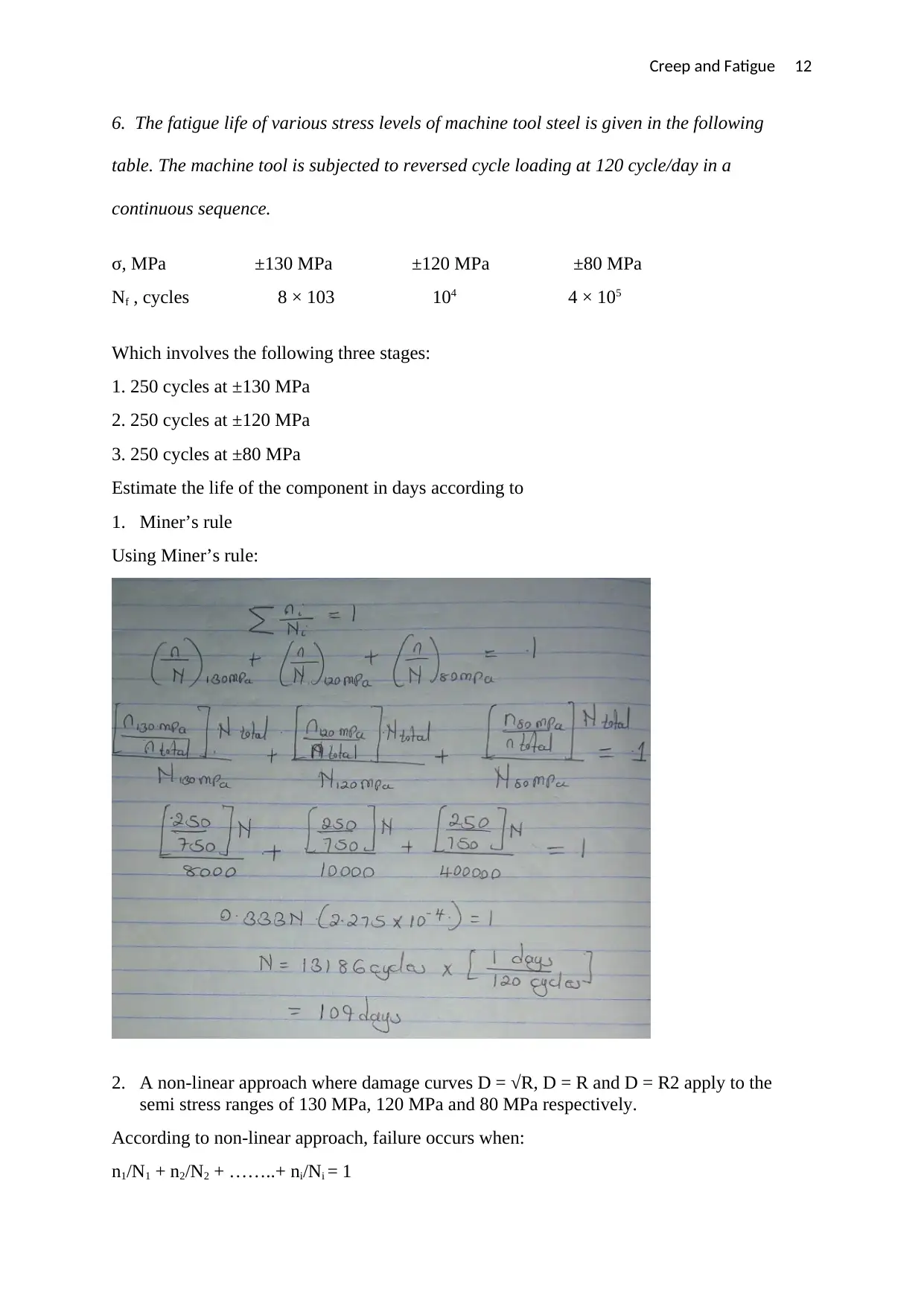
1. Miner’s rule
Using Miner’s rule:
2. A non-linear approach where damage curves D = √R, D = R and D = R2 apply to the
semi stress ranges of 130 MPa, 120 MPa and 80 MPa respectively.
According to non-linear approach, failure occurs when:
n1/N1 + n2/N2 + ……..+ ni/Ni = 1
⊘ This is a preview!⊘
Do you want full access?
Subscribe today to unlock all pages.

Trusted by 1+ million students worldwide
1 out of 16
Related Documents
Your All-in-One AI-Powered Toolkit for Academic Success.
+13062052269
info@desklib.com
Available 24*7 on WhatsApp / Email
![[object Object]](/_next/static/media/star-bottom.7253800d.svg)
Unlock your academic potential
Copyright © 2020–2026 A2Z Services. All Rights Reserved. Developed and managed by ZUCOL.

