Network Design, Configuration, and Management Report - CSC73002

Verified

Added on  2022/10/12

|18
|1791
|183
Report
AI Summary
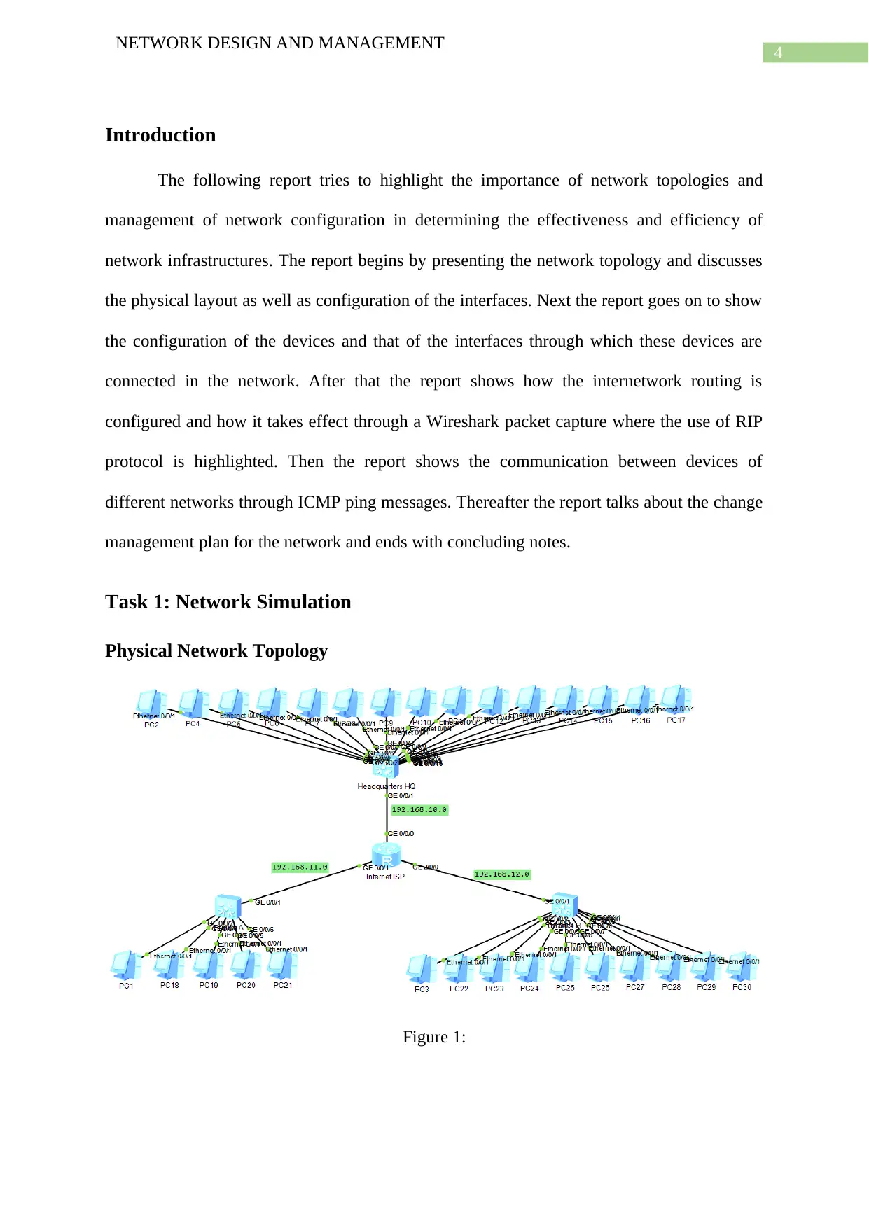
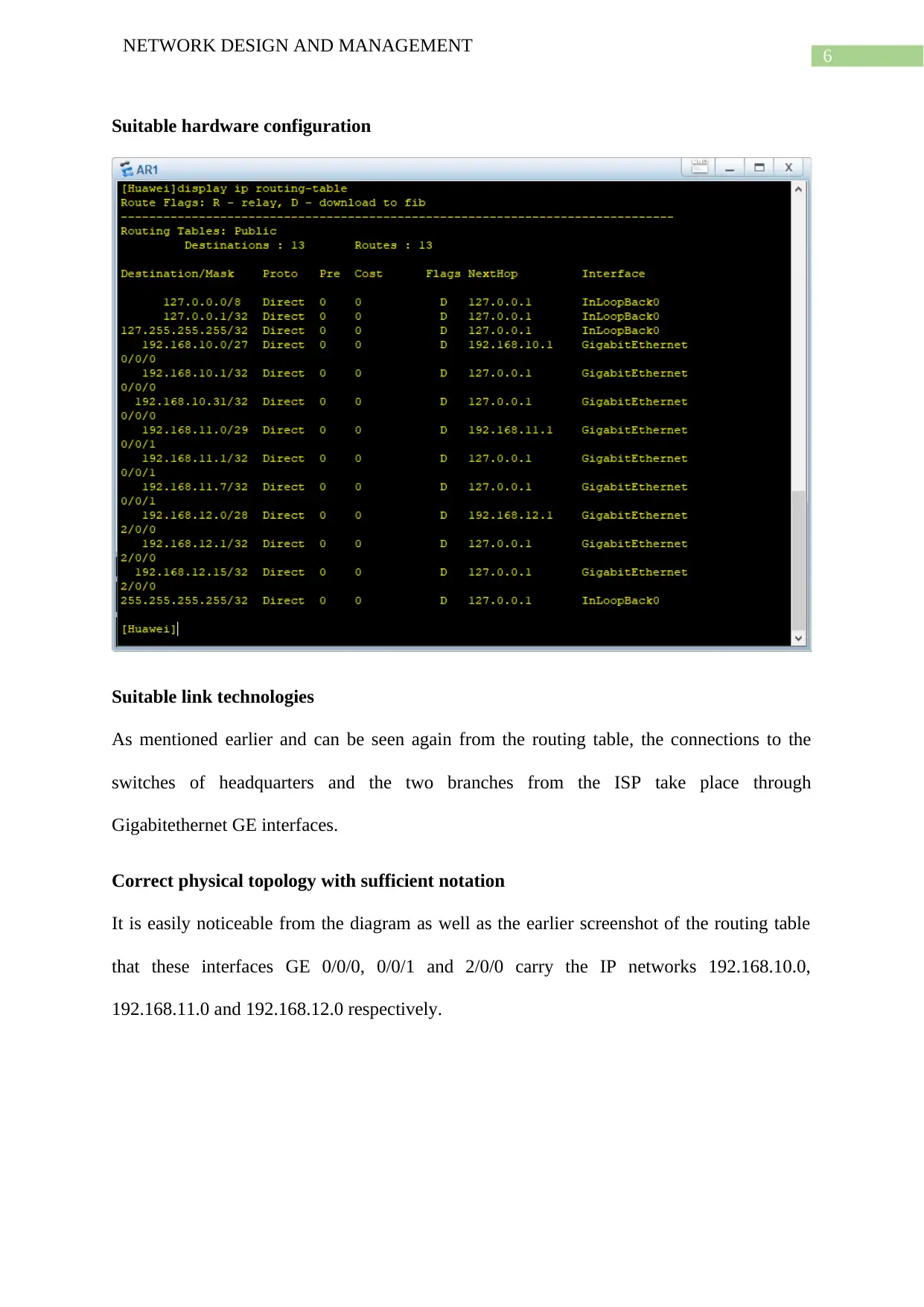
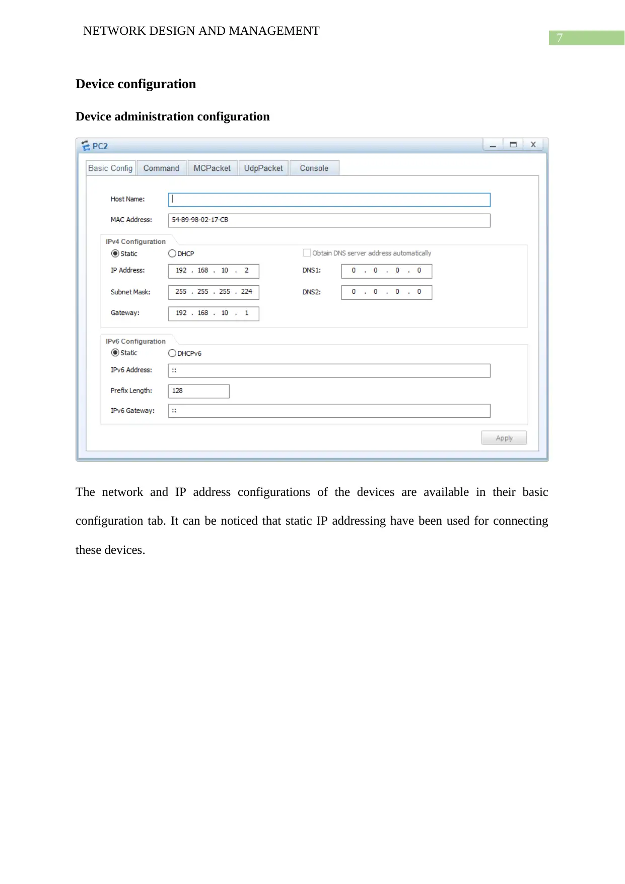
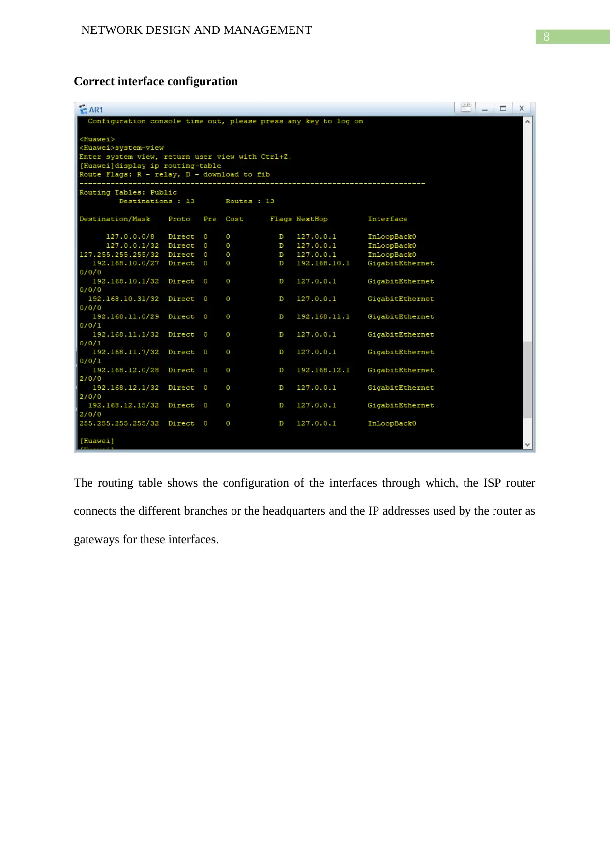
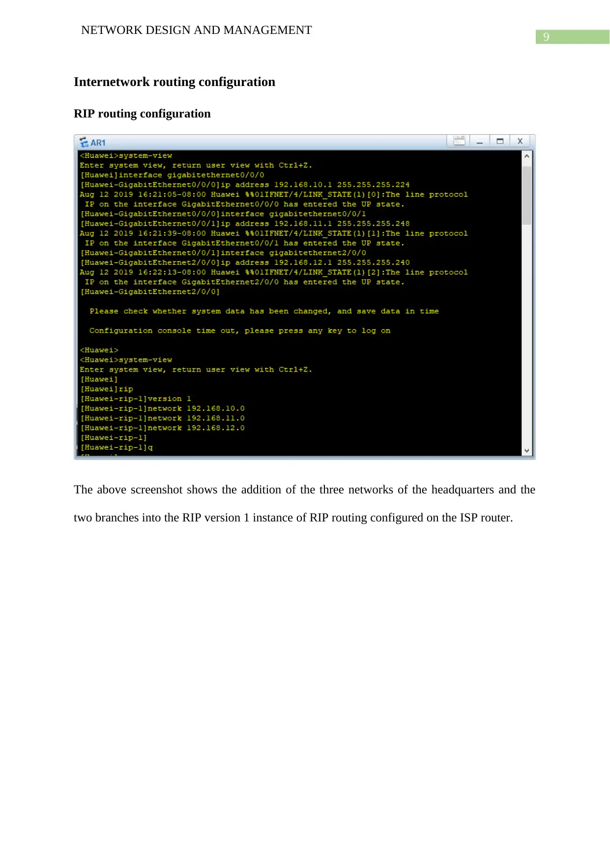
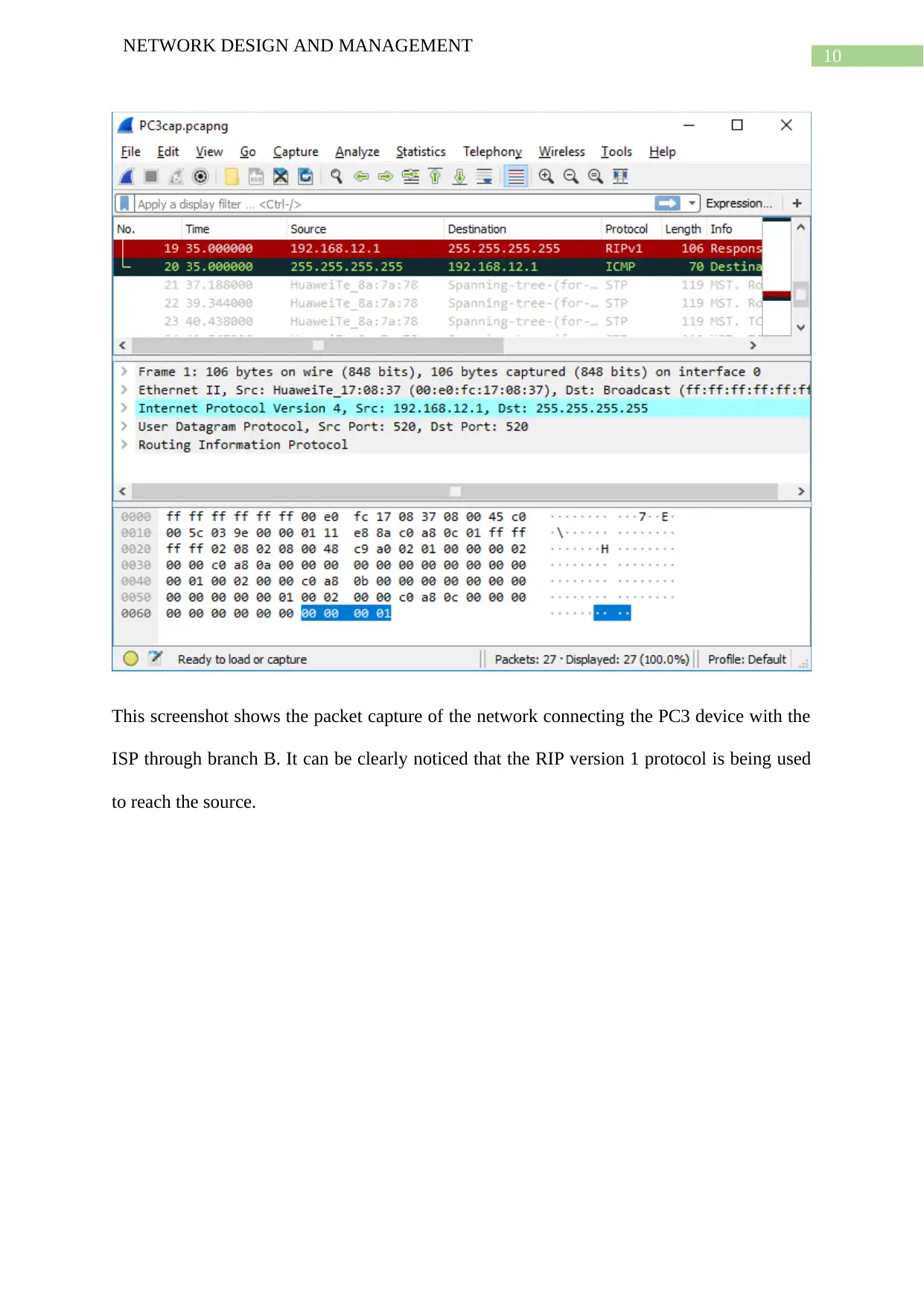
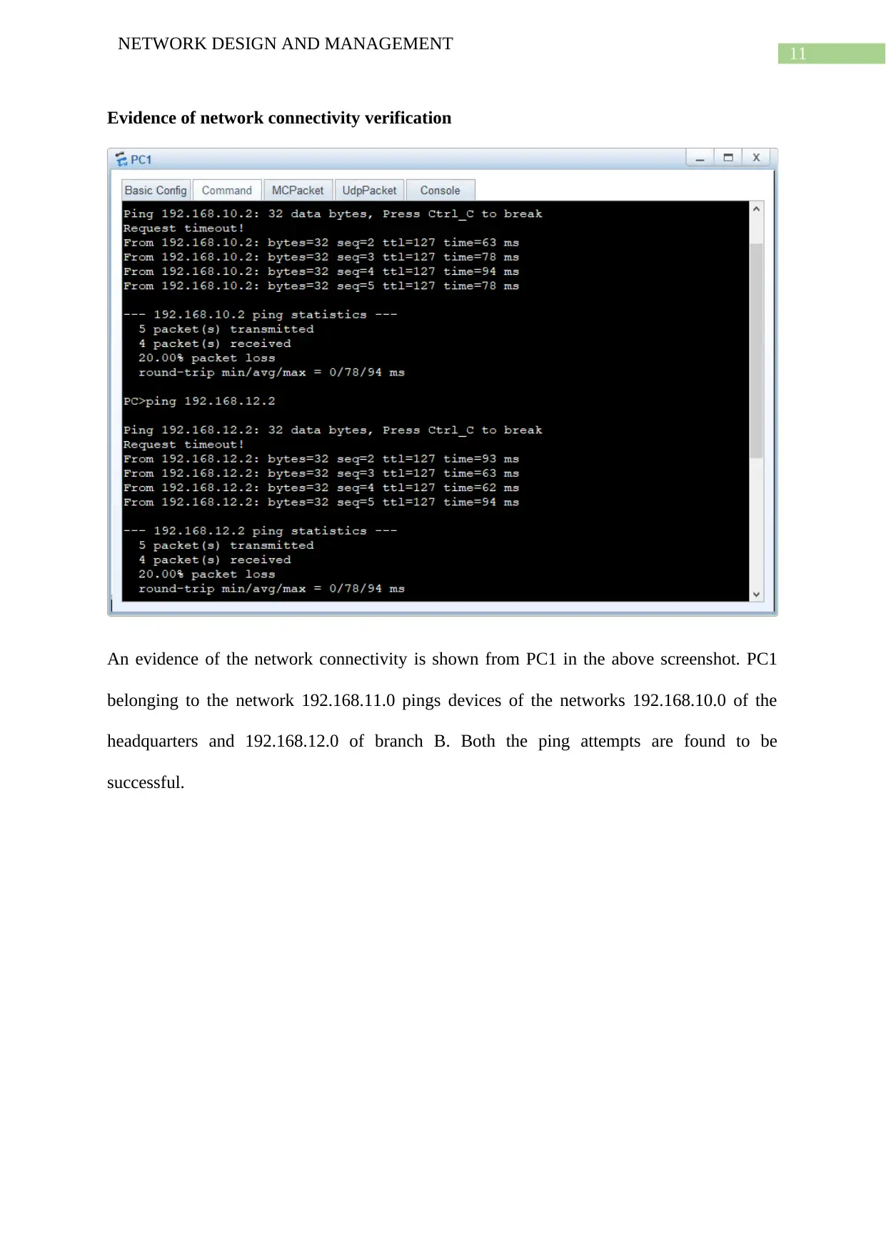
This report analyzes network design and management within a simulated enterprise environment, focusing on a network lab mimicking a Headquarter and two branches connected over the Internet. It begins by presenting the network topology, physical layout, and interface configurations. The report then details device configurations, including administration settings and interface setups. A key aspect is the configuration of internetwork routing, demonstrated through RIP protocol usage and Wireshark packet captures. The report also shows communication between different networks using ICMP ping messages. Furthermore, the report delves into a change management plan for the network and concludes with references. The network utilizes Huawei routers and switches, and the report covers both logical and physical network layouts, including hardware and software requirements. The report also includes evidence of network connectivity verification and current device configurations.
Document Page
Running head: NETWORK DESIGN AND MANAGEMENT
Network Design and Management
Name of the Student
Name of the University
Author Note
tabler-icon-diamond-filled.svg

Paraphrase This Document

Need a fresh take? Get an instant paraphrase of this document with our AI Paraphraser
Document Page
1
NETWORK DESIGN AND MANAGEMENT
Abstract
There are numerous researches conducted so far that highlight the importance of network
topologies and management of network configuration in determining the effectiveness and
efficiency of network infrastructures. First the report presents the network topology and
discusses the physical layout as well as configuration of the interfaces. Next the report goes
on to show the configuration of the devices and that of the interfaces through which these
devices are connected in the network. After that the report shows how the internetwork
routing is configured and how it takes effect through a Wireshark packet capture where the
use of RIP protocol is highlighted. Then the report shows the communication between
devices of different networks through ICMP ping messages. Thereafter the report talks about
the change management plan for the network and ends with concluding notes.
Document Page
2
NETWORK DESIGN AND MANAGEMENT
Table of Contents
Introduction................................................................................................................................3
Task 1: Network Simulation......................................................................................................3
Physical Network Topology...................................................................................................3
Suitable hardware configuration........................................................................................5
Suitable link technologies..................................................................................................5
Correct physical topology with sufficient notation............................................................5
Device configuration..............................................................................................................6
Device administration configuration..................................................................................6
Correct interface configuration..........................................................................................7
Internetwork routing configuration........................................................................................8
RIP routing configuration..................................................................................................8
Evidence of network connectivity verification................................................................10
Task 2: Network configuration management...........................................................................11
Network Topology...............................................................................................................11
Network Hardware and Software Requirements..................................................................11
Current configuration of devices......................................................................................12
Change Management........................................................................................................13
Conclusion................................................................................................................................13
Bibliography.............................................................................................................................15
Document Page
3
NETWORK DESIGN AND MANAGEMENT
tabler-icon-diamond-filled.svg

Paraphrase This Document

Need a fresh take? Get an instant paraphrase of this document with our AI Paraphraser
Document Page
4
NETWORK DESIGN AND MANAGEMENT
Introduction
The following report tries to highlight the importance of network topologies and
management of network configuration in determining the effectiveness and efficiency of
network infrastructures. The report begins by presenting the network topology and discusses
the physical layout as well as configuration of the interfaces. Next the report goes on to show
the configuration of the devices and that of the interfaces through which these devices are
connected in the network. After that the report shows how the internetwork routing is
configured and how it takes effect through a Wireshark packet capture where the use of RIP
protocol is highlighted. Then the report shows the communication between devices of
different networks through ICMP ping messages. Thereafter the report talks about the change
management plan for the network and ends with concluding notes.
Task 1: Network Simulation
Physical Network Topology
Figure 1:
Document Page
5
NETWORK DESIGN AND MANAGEMENT
As can be seen from the above figure the physical topology of the network involves the
computers of the headquarters as well as that of the branches A and B. These three branches
are connected with one another through the internet. The network used for the headquarters is
192.168.10.0. The network used for the branch A is 192.168.11.0 and that for the branch C is
192.168.12.0. The ISP router uses the interfaces GE 0/0/0, 0/0/1 and 2/0/0 for the
headquarters, branch A and branch B respectively. The computers or PCs are connected via
ethernet 0/0/1 interfaces with the switches of these branches.
Document Page
6
NETWORK DESIGN AND MANAGEMENT
Suitable hardware configuration
Suitable link technologies
As mentioned earlier and can be seen again from the routing table, the connections to the
switches of headquarters and the two branches from the ISP take place through
Gigabitethernet GE interfaces.
Correct physical topology with sufficient notation
It is easily noticeable from the diagram as well as the earlier screenshot of the routing table
that these interfaces GE 0/0/0, 0/0/1 and 2/0/0 carry the IP networks 192.168.10.0,
192.168.11.0 and 192.168.12.0 respectively.
tabler-icon-diamond-filled.svg

Paraphrase This Document

Need a fresh take? Get an instant paraphrase of this document with our AI Paraphraser
Document Page
7
NETWORK DESIGN AND MANAGEMENT
Device configuration
Device administration configuration
The network and IP address configurations of the devices are available in their basic
configuration tab. It can be noticed that static IP addressing have been used for connecting
these devices.
Document Page
8
NETWORK DESIGN AND MANAGEMENT
Correct interface configuration
The routing table shows the configuration of the interfaces through which, the ISP router
connects the different branches or the headquarters and the IP addresses used by the router as
gateways for these interfaces.
Document Page
9
NETWORK DESIGN AND MANAGEMENT
Internetwork routing configuration
RIP routing configuration
The above screenshot shows the addition of the three networks of the headquarters and the
two branches into the RIP version 1 instance of RIP routing configured on the ISP router.
tabler-icon-diamond-filled.svg

Paraphrase This Document

Need a fresh take? Get an instant paraphrase of this document with our AI Paraphraser
Document Page
10
NETWORK DESIGN AND MANAGEMENT
This screenshot shows the packet capture of the network connecting the PC3 device with the
ISP through branch B. It can be clearly noticed that the RIP version 1 protocol is being used
to reach the source.
Document Page
11
NETWORK DESIGN AND MANAGEMENT
Evidence of network connectivity verification
An evidence of the network connectivity is shown from PC1 in the above screenshot. PC1
belonging to the network 192.168.11.0 pings devices of the networks 192.168.10.0 of the
headquarters and 192.168.12.0 of branch B. Both the ping attempts are found to be
successful.
chevron_up_icon
1 out of 18
circle_padding
hide_on_mobile
zoom_out_icon
[object Object]