Analysis of Bending Stress in Curved Beams Under Earthquake Conditions
VerifiedAdded on 2023/05/26
|49
|13386
|246
Report
AI Summary
This report delves into the analysis of bending stress in curved beams, focusing on their behavior under earthquake conditions. It explores the application of formulas to determine stress, the impact of seismic activities on curved structures like bridges, and the use of shake table models to simulate earthquake effects. The report also compares the behavior of modern and ancient arches, discussing failure modes and the role of masonry. Furthermore, it examines torsional buckling in beams, its causes, and examples of structures where it has occurred. The report provides a comprehensive overview of the structural analysis of curved beams and their resilience in seismic events, along with the significance of expansion joints and the influence of earthquake input angles. The study covers a wide range of civil engineering aspects related to structural design, earthquake resistance, and the behavior of different structural elements under stress.
Running head: BENDING STRESS IN CURVED BEAM
BENDING STRESS IN CURVED BEAM
BENDING STRESS IN CURVED BEAM
Paraphrase This Document
Need a fresh take? Get an instant paraphrase of this document with our AI Paraphraser
BENDING STRESS IN CURVED BEAM 1
Table of Contents
Introduction......................................................................................................................................2
Task 1: Bending of curved beams...................................................................................................3
1.1 The behaviour of curved beams in past earthquakes.............................................................3
1.2 Shake table model..................................................................................................................6
1.3 Examples of constructions using curved beams..................................................................10
Task 2: Behavior of modern arches vs. the behavior of ancient arches (masonry).......................14
2.1 Failure modes.......................................................................................................................14
2.2 The behaviour of arches in past earthquakes.......................................................................17
2.3 Examples of modern arches and ancient arches...................................................................22
Task 3: Torsional buckling of beams.............................................................................................24
3.1 The reasons behind torsional buckling of beams.................................................................24
3.2 Examples of constructions where the torsional buckling of beams has occurred................25
Conclusion.....................................................................................................................................34
References......................................................................................................................................36
BENDING STRESS IN CURVED BEAM 2
Introduction
A curved beam is generally referred to as a body, the geometric figure of which has been
created by the motion of a plane figure in space. The plane figure is termed as the cross-section
of the curved beam, wherein the center of gravity of the beam consistently follows an axis or a
specific curve. The cross-section of a curved beam can be effectively used to identify the
differences in the curved beams. This study focuses on the curvature of beams concerning
earthquakes. In addition to that, a comparative analysis is mentioned with regards to the varied
behaviour of arches of ancient times with the arches of modern times. For instance, ancient
arches may be illustrated through several medieval architectures, while modern construction
works, such as bridges may be cited as examples of modern arches.
A masonry arch is known to comprise several components, such as a keystone, a
voissour, an impost, an extrados, and an intrados. The other components include a clear span, a
rise, and an abutment. Various types and categories of arches have been explored in this regards
as well. Since beams and may arches are restrained as well as unrestrained, an occurrence
commonly termed as the torsional buckling of beams is found to be prevalent in case the
compression flange becomes free and is found to rotate after being displaced laterally. The
torsional effect has been found to be a result of the combination of both the tensile and the
compressive forces. The reasons for such occurrence have been explored in this study, and the
potential actions for the mitigation of the challenges have been identified in this regards as well.
⊘ This is a preview!⊘
Do you want full access?
Subscribe today to unlock all pages.
Trusted by 1+ million students worldwide
BENDING STRESS IN CURVED BEAM 3
Task 1: Bending of curved beams
1.1 The behaviour of curved beams in past earthquakes
To evaluate the behaviour of curved beams, it is necessary to consider the design of the
curved beam in question. Considering that the area of cross-sectional of a beam is symmetrical, it
is to be estimated that the impact of the load, which is placed at the plane of symmetry. It may be
mentioned in this context that the axis of symmetry is evident on the plane of curvature.
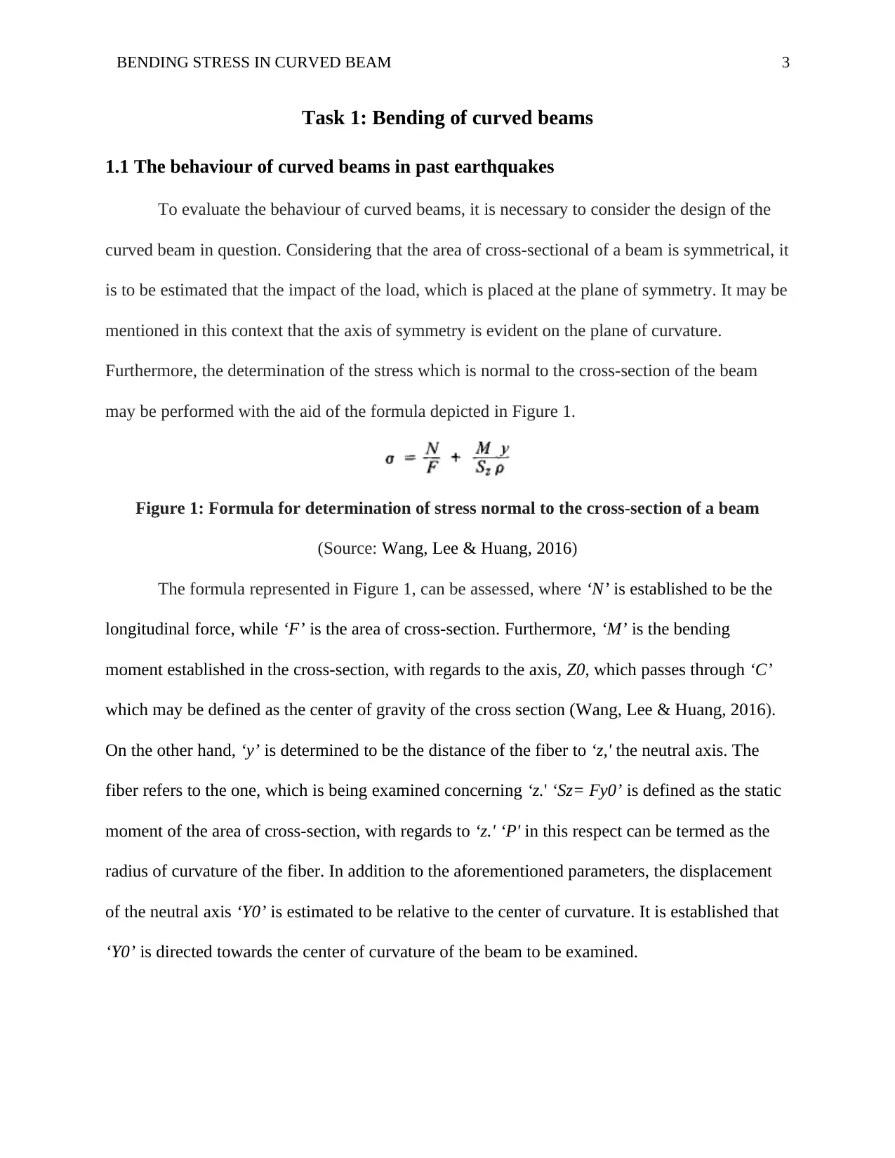
Furthermore, the determination of the stress which is normal to the cross-section of the beam
may be performed with the aid of the formula depicted in Figure 1.
Figure 1: Formula for determination of stress normal to the cross-section of a beam
(Source: Wang, Lee & Huang, 2016)
The formula represented in Figure 1, can be assessed, where ‘N’ is established to be the
longitudinal force, while ‘F’ is the area of cross-section. Furthermore, ‘M’ is the bending
moment established in the cross-section, with regards to the axis, Z0, which passes through ‘C’
which may be defined as the center of gravity of the cross section (Wang, Lee & Huang, 2016).
On the other hand, ‘y’ is determined to be the distance of the fiber to ‘z,' the neutral axis. The
fiber refers to the one, which is being examined concerning ‘z.' ‘Sz= Fy0’ is defined as the static
moment of the area of cross-section, with regards to ‘z.' ‘P' in this respect can be termed as the
radius of curvature of the fiber. In addition to the aforementioned parameters, the displacement
of the neutral axis ‘Y0’ is estimated to be relative to the center of curvature. It is established that
‘Y0’ is directed towards the center of curvature of the beam to be examined.
Task 1: Bending of curved beams
1.1 The behaviour of curved beams in past earthquakes
To evaluate the behaviour of curved beams, it is necessary to consider the design of the
curved beam in question. Considering that the area of cross-sectional of a beam is symmetrical, it
is to be estimated that the impact of the load, which is placed at the plane of symmetry. It may be
mentioned in this context that the axis of symmetry is evident on the plane of curvature.
Furthermore, the determination of the stress which is normal to the cross-section of the beam
may be performed with the aid of the formula depicted in Figure 1.
Figure 1: Formula for determination of stress normal to the cross-section of a beam
(Source: Wang, Lee & Huang, 2016)
The formula represented in Figure 1, can be assessed, where ‘N’ is established to be the
longitudinal force, while ‘F’ is the area of cross-section. Furthermore, ‘M’ is the bending
moment established in the cross-section, with regards to the axis, Z0, which passes through ‘C’
which may be defined as the center of gravity of the cross section (Wang, Lee & Huang, 2016).
On the other hand, ‘y’ is determined to be the distance of the fiber to ‘z,' the neutral axis. The
fiber refers to the one, which is being examined concerning ‘z.' ‘Sz= Fy0’ is defined as the static
moment of the area of cross-section, with regards to ‘z.' ‘P' in this respect can be termed as the
radius of curvature of the fiber. In addition to the aforementioned parameters, the displacement
of the neutral axis ‘Y0’ is estimated to be relative to the center of curvature. It is established that
‘Y0’ is directed towards the center of curvature of the beam to be examined.
Paraphrase This Document
Need a fresh take? Get an instant paraphrase of this document with our AI Paraphraser
BENDING STRESS IN CURVED BEAM 4
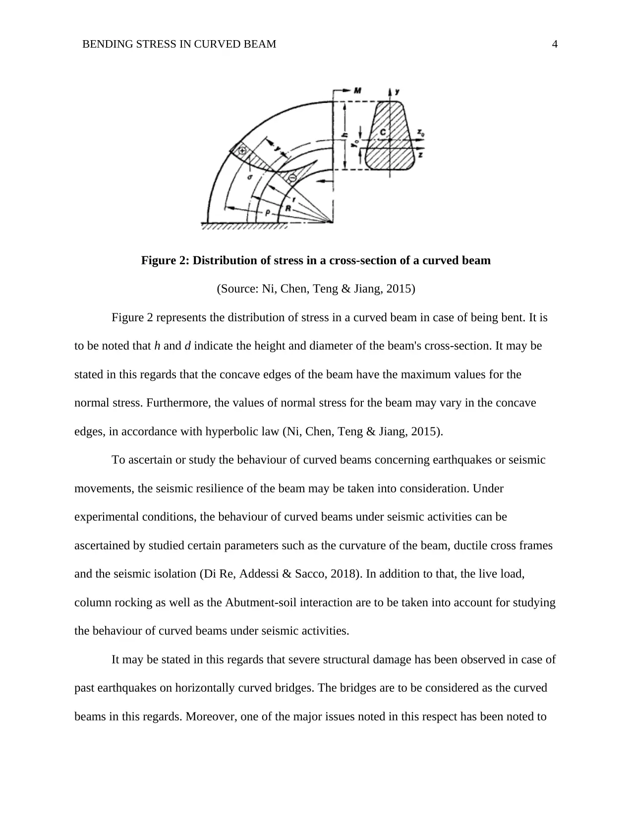
Figure 2: Distribution of stress in a cross-section of a curved beam
(Source: Ni, Chen, Teng & Jiang, 2015)
Figure 2 represents the distribution of stress in a curved beam in case of being bent. It is
to be noted that h and d indicate the height and diameter of the beam's cross-section. It may be
stated in this regards that the concave edges of the beam have the maximum values for the
normal stress. Furthermore, the values of normal stress for the beam may vary in the concave
edges, in accordance with hyperbolic law (Ni, Chen, Teng & Jiang, 2015).
To ascertain or study the behaviour of curved beams concerning earthquakes or seismic
movements, the seismic resilience of the beam may be taken into consideration. Under
experimental conditions, the behaviour of curved beams under seismic activities can be
ascertained by studied certain parameters such as the curvature of the beam, ductile cross frames
and the seismic isolation (Di Re, Addessi & Sacco, 2018). In addition to that, the live load,
column rocking as well as the Abutment-soil interaction are to be taken into account for studying
the behaviour of curved beams under seismic activities.
It may be stated in this regards that severe structural damage has been observed in case of
past earthquakes on horizontally curved bridges. The bridges are to be considered as the curved
beams in this regards. Moreover, one of the major issues noted in this respect has been noted to
BENDING STRESS IN CURVED BEAM 5
be the unseating of the deck from the abutment (Di Re, Addessi & Sacco, 2018). This has been
identified as a result of the excessive plane-body motion of the decks, resulting from the seismic
activities. The irregular geometry of the curved beam along with the seismic poundings observed
between the abutments and the decks have been noted to be the prime cause of the failure of the
curved beam structures.
Furthermore, it may be stated in this regards that the maximum seismic response of the curved
beam has been found to be relevant to the angle of input of the designated earthquake (Miyamoto
et al., 2016). The irregularities in the structure of the curved beam or the curved bridge can be
attributed to the interaction between the torsion forces and the moment. The response of the
curved beam structure in response to the input of the one-way earthquake can be determined
through the uniform expression derived from the unfavorable angle of the earthquake. Hence, the
maximum response of the curved beam structure corresponding to the seismic activities of the
earthquake can be determined.
⊘ This is a preview!⊘
Do you want full access?
Subscribe today to unlock all pages.
Trusted by 1+ million students worldwide
BENDING STRESS IN CURVED BEAM 6
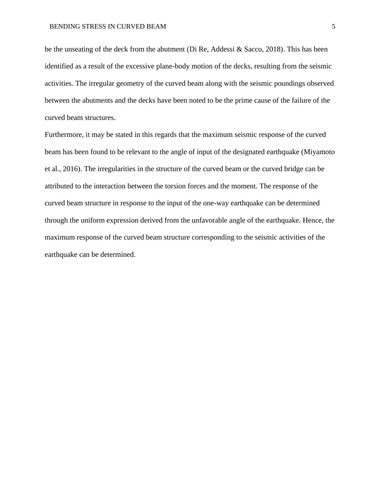
Figure 3: Input angles of earthquake acceleration
(Source: Li & Du, 2015)
Figure 3 represents the various input angles of earthquake acceleration. Figure 3(a)
depicts a single-direction input, while Figure 3(b) depicts orthotropic dual-direction inputs. On
the contrary, Figure 3(c) illustrates Skewed dual-direction inputs relating to the seismic activities
of the earthquakes. The input angles are considered concerning a random direction in a plane.
The implementation of the concept of a curved bridge has been widely prevalent in
several architectural structures. The constructions of railways have a widespread implementation
of the curved beams. However, since the 1970s, multiple devastating earthquakes have been
noted by engineers. The impact of the earthquakes on the curved beams or the girder bridge,
which constitutes an important variation of the curved beams, is regarded as vital for the study
(Hsu & Halim, 2017). For instance, the 1971 earthquake of San Fernando is known to have
Paraphrase This Document
Need a fresh take? Get an instant paraphrase of this document with our AI Paraphraser
BENDING STRESS IN CURVED BEAM 7
caused extensive damage to a multi-span girder bridge. Hence, special attention has been paid to
the seismic responses generated by curved beams or bridges, as a subject for study and
understanding in the field of engineering (Pydah & Sabale, 2017). The Shake table model has
been noted in this regards to developing a better understanding and knowledge concerning the
matter.
1.2 Shake table model
The shake table model has been an extensive aspect of earthquake engineering. The use
and application of the shake table model are observed as a technique implemented to test the
response of certain structures, such as curved beams, or girder bridges to extensive earthquakes.
Furthermore, the study of the seismic performance of rock slopes and soil is also undertaken
through the shake table model. This model is typically used for the evaluation of the performance
of scales slopes, curved beams, and other structural models with the aid of imitating is simulating
earthquakes recorded over some time (Attary et al., 2015). The specimen or the curved beam or
the curved bridge to be shaken is experimented on until it reaches the point of ‘failure.' With the
aid of modern devices and other innovative technologies, it is possible to interpret the dynamic
behaviour of the curved beams exposed to the artificially simulated earthquakes. The degrees of
freedom are generally considered as 6 in this case of the experiment.
BENDING STRESS IN CURVED BEAM 8
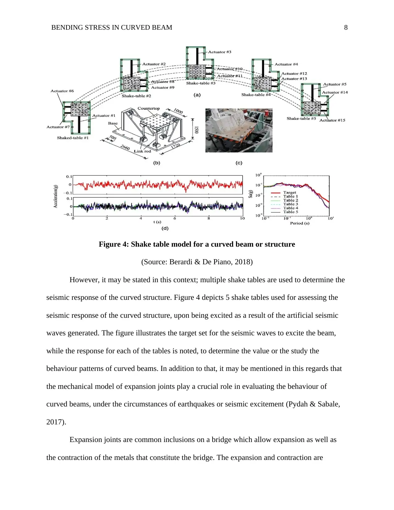
Figure 4: Shake table model for a curved beam or structure
(Source: Berardi & De Piano, 2018)
However, it may be stated in this context; multiple shake tables are used to determine the
seismic response of the curved structure. Figure 4 depicts 5 shake tables used for assessing the
seismic response of the curved structure, upon being excited as a result of the artificial seismic
waves generated. The figure illustrates the target set for the seismic waves to excite the beam,
while the response for each of the tables is noted, to determine the value or the study the
behaviour patterns of curved beams. In addition to that, it may be mentioned in this regards that
the mechanical model of expansion joints play a crucial role in evaluating the behaviour of
curved beams, under the circumstances of earthquakes or seismic excitement (Pydah & Sabale,
2017).
Expansion joints are common inclusions on a bridge which allow expansion as well as
the contraction of the metals that constitute the bridge. The expansion and contraction are
⊘ This is a preview!⊘
Do you want full access?
Subscribe today to unlock all pages.
Trusted by 1+ million students worldwide
BENDING STRESS IN CURVED BEAM 9
generally consistent with the temperature variations that are a frequent and common occurrence.
Regardless, the absorption of shocks related to the seismic transitions is also regarded as a part of
the application for expansion joints (Berardi & De Piano, 2018). Hence the accommodation of
any machine as well as thermal changes within the system can be achieved through the
implementation of expansion joints in curved beams or curved bridges. The use of reinforced
steel and other steel structures, along with prestressed concrete are used for the development of
the bridge expansion joints to make it be able to withstand seismic activities, which the curved
bridge may be subjected to.
A variety of expansion joints are noted to be in existence. For instance, the expansion
joints are prepared such that it can accommodate certain specific changes being made to the
curved structure. Considering the example of a bridge, one may note that generally, expansion
joints focus on accommodating movement within the range of 30 to 1,200 millimeters (Sun, Cui,
Qin & Hou, 2018). These joints are designed to withstand from small to medium, as well as
large-scale movement. Since this study would eventually discuss the role of masonry in the
resistance towards earthquake on various kinds of arches, it may be suitable to discuss the issues
related to masonry and expansion joints. The curved structures, often made out of masonry may
also display resilience towards seismic activities. The manufacture of rubber expansion joints has
been undertaken to reduce cracks, as well as for shock absorption from the past series of
earthquakes.
It may be mentioned in this regards, that despite major attempts at establishing the
stability of the expansion joints for the curved beams, a failure mode may be evident. The
inability to support or withstand the seismic activities or shocks often results in a failure mode.
The phenomena of collision and yielding have often been responsible for the failure mode
Paraphrase This Document
Need a fresh take? Get an instant paraphrase of this document with our AI Paraphraser
BENDING STRESS IN CURVED BEAM 10
(Berardi & De Piano, 2018). However, the study of these phenomena under seismic shocks can
be used to analyse and evaluate the role or the influence of the expansion joints of the curved
bridges. The study chiefly focuses on assessing the response of the curved beam or the curved
bridge to gather a better understanding of the events. As initially depicted in Figure 3, the multi-
directional inputs of earthquakes have been demonstrated, which aids in the development of an
understanding of the SDOF structure as well. SDOF refers to the single degree of freedom, as
applied previously for the Shake table model, which implements the use of 6 degrees of freedom,
as opposed to one in the SDOF for the study of the multi-directional inputs of earthquakes (Sun,
Cui, Qin & Hou, 2018).
Evaluative studies have been performed upon analysing the deformation of the piers, as
well as the collision and sliding of the expansion joints involved in the curved bridges. It may be
mentioned in this context that among several methods for performing a seismic analysis, the use
of the SRSS combination methods has been focused on by various engineers and scientists.
SRSS, also known as the square root of the sum of the squares is one of the widely preferred
methods for performing the seismic analysis. With the aid of the SRSS method, the use of
response spectrum analysis has been implemented, to analyse the factors involved in the
generation of seismic response (Berardi & De Piano, 2018). The type of pier connection used, as
well as the beam, and the curvature was analysed as being part of the contributing factors.
Furthermore, the use of the complete quadratic combination 3 or the CQC3 method was
implemented to assess the seismic response of the curved structures used in the case study
(Lemos & Campos Costa, 2017).
Regardless, it may be stated in this aspect that the implementation of the Caltrans Seismic
Design Criteria, put forward in 2013, have been found to be the most effective regarding
BENDING STRESS IN CURVED BEAM 11
generating results for the seismic response. The elastic earthquake response can be calculated
from the design above criteria. However, undertaking a study on the better evaluation of a
particular type of curved structure, it was noted that the Caltrans method is more appropriate for
the study of the curved girder bridge (Lemos & Campos Costa, 2017). The reason for the
implementation of the Caltrans method is determined as the suitability of the options regarding
the detailed differences in the construction, while the seismic behaviour is observed in
accordance with the seismic behaviour.
1.3 Examples of constructions using curved beams
The complex geometry involved in the construction, as well as the fabrication of curved
beams, discussed in this study, provides an example of the wide applicability of curved beams.
Furthermore, the study aims at addressing the process of fabrication that implements elastic
deformation for the construction of development using curved beams. Expanding control over
the curvature of the beams as well as the design surface may aid in the establishment of a
network of a quadrilateral mesh, along with a spherical vertex (Sun, Cui, Qin & Hou, 2018). The
advantage of the aforementioned construction can be regarded as the geometric structure which
provides immense support. A symbiosis of the geometry, the fabrication, as well as the load-
bearing behavior of the curved beam structures can be studied in this regards to gathering a better
understanding of the constructions which use curved beams.
A prime example of a construction which implements the use of curved beams can be
cited as the Asymptotic Gridshell which can be designed for courtyards. Figure 5 depicts various
kinds of Gridshell which can be constructed with the aid of curved beams. The figure
demonstrates the principal curvature lines which constitute the major framework for the
gridshell. Furthermore, a traditional gridshell is depicted in the figure, while illustrating the
⊘ This is a preview!⊘
Do you want full access?
Subscribe today to unlock all pages.
Trusted by 1+ million students worldwide
1 out of 49


Your All-in-One AI-Powered Toolkit for Academic Success.
+13062052269
info@desklib.com
Available 24*7 on WhatsApp / Email
![[object Object]](/_next/static/media/star-bottom.7253800d.svg)
Unlock your academic potential
Copyright © 2020–2026 A2Z Services. All Rights Reserved. Developed and managed by ZUCOL.