Cyber Engineering Project: Design of a Tuning Circuit and FM Modulator
VerifiedAdded on 2022/11/13
|22
|4283
|400
Project
AI Summary
This project delves into the design and analysis of several key components in cyber engineering. The first section focuses on the design of a tuning circuit capable of receiving multiple frequencies, exploring the use of superheterodyne principles, Q-factor considerations, and circuit optimization for specific frequency ranges (96MHz, 100MHz, and 104MHz). It also addresses mechanisms to avoid side channel noise and improve frequency selection, discussing countermeasures like shielding, filtering, physical enclosures, jamming, and cryptographic code. The second part of the project involves the design of an indirect FM modulator, including a block diagram and the expected parameters. Finally, the project explores a remote attendance system based on RFID technology and GSM network. This includes a detailed explanation of the system design, hardware structure (RFID reader, GSM module), software design, and the advantages of using RFID for attendance monitoring. The document provides a comprehensive overview of the system's components, characteristics, and operation.
CYBER ENGINEERING 1
CYBER ENGINEERING
Name of Student
Institution Affiliation
CYBER ENGINEERING
Name of Student
Institution Affiliation
Paraphrase This Document
Need a fresh take? Get an instant paraphrase of this document with our AI Paraphraser
CYBER ENGINEERING 2
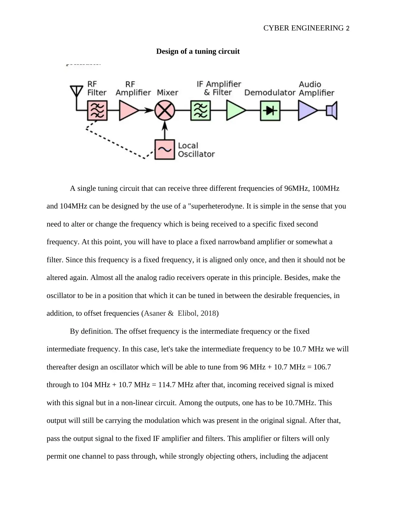
Design of a tuning circuit
A single tuning circuit that can receive three different frequencies of 96MHz, 100MHz
and 104MHz can be designed by the use of a "superheterodyne. It is simple in the sense that you
need to alter or change the frequency which is being received to a specific fixed second
frequency. At this point, you will have to place a fixed narrowband amplifier or somewhat a
filter. Since this frequency is a fixed frequency, it is aligned only once, and then it should not be
altered again. Almost all the analog radio receivers operate in this principle. Besides, make the
oscillator to be in a position that which it can be tuned in between the desirable frequencies, in
addition, to offset frequencies (Asaner & Elibol, 2018)
By definition. The offset frequency is the intermediate frequency or the fixed
intermediate frequency. In this case, let's take the intermediate frequency to be 10.7 MHz we will
thereafter design an oscillator which will be able to tune from 96 MHz + 10.7 MHz = 106.7
through to 104 MHz + 10.7 MHz = 114.7 MHz after that, incoming received signal is mixed
with this signal but in a non-linear circuit. Among the outputs, one has to be 10.7MHz. This
output will still be carrying the modulation which was present in the original signal. After that,
pass the output signal to the fixed IF amplifier and filters. This amplifier or filters will only
permit one channel to pass through, while strongly objecting others, including the adjacent
CYBER ENGINEERING 3
signals. In addition, an RF amplifier can as well be used ahead of the mixer. The amplifier,
however, will be composed of a fixed tuned circuit with a full band that has the capability of
covering the entire groups of interest. In this case, it will cover the frequencies of 96MHz,
100MHz, and 104MHz. A simple tunable circuit that is "ganged" with the local oscillator tuning
circuit can as well be utilized as it is preferable by many designers (Bada et al., 2019).
Alternatively,
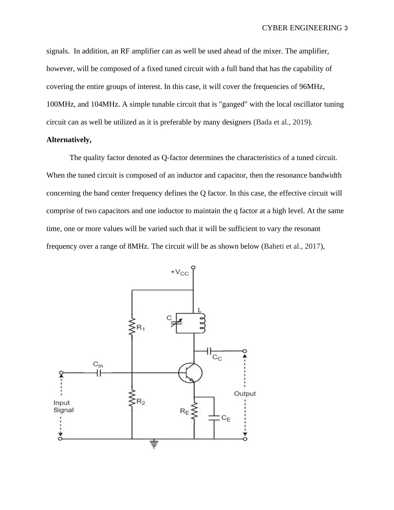
The quality factor denoted as Q-factor determines the characteristics of a tuned circuit.
When the tuned circuit is composed of an inductor and capacitor, then the resonance bandwidth
concerning the band center frequency defines the Q factor. In this case, the effective circuit will
comprise of two capacitors and one inductor to maintain the q factor at a high level. At the same
time, one or more values will be varied such that it will be sufficient to vary the resonant
frequency over a range of 8MHz. The circuit will be as shown below (Baheti et al., 2017),
signals. In addition, an RF amplifier can as well be used ahead of the mixer. The amplifier,
however, will be composed of a fixed tuned circuit with a full band that has the capability of
covering the entire groups of interest. In this case, it will cover the frequencies of 96MHz,
100MHz, and 104MHz. A simple tunable circuit that is "ganged" with the local oscillator tuning
circuit can as well be utilized as it is preferable by many designers (Bada et al., 2019).
Alternatively,
The quality factor denoted as Q-factor determines the characteristics of a tuned circuit.
When the tuned circuit is composed of an inductor and capacitor, then the resonance bandwidth
concerning the band center frequency defines the Q factor. In this case, the effective circuit will
comprise of two capacitors and one inductor to maintain the q factor at a high level. At the same
time, one or more values will be varied such that it will be sufficient to vary the resonant
frequency over a range of 8MHz. The circuit will be as shown below (Baheti et al., 2017),
⊘ This is a preview!⊘
Do you want full access?
Subscribe today to unlock all pages.
Trusted by 1+ million students worldwide
CYBER ENGINEERING 4
The center frequency will be =
f = 1 / 2pi x sqrt (Lx C)
An amplifier circuit constructs the circuit with a parallel tuned circuit at the collector
load. At L, a secondary winding can help in generating the output, which can also be obtained
in the coupling capacitor CC. At the amplifier input, the 100 MHz frequency is applied. The
resonant frequency is also made to be 100MHz by way of altering the capacitance value
(capacitor in parallel with the inductor). This results in a high impedance, which maximizes the
tuned circuit output. However, the high impedance is concerning the tuned frequency, which is
100MHz, other frequencies will be restricted. The maximum impedance makes the circuitry thus
to be purely resistive, making the voltage gain to be maximum (Ben-Asher & Gonzalez, 2015).
This makes the gain to drop above, and below the resonant frequency, hence incorporating the
other frequencies. I.e., 96MHZ and 104 MHz. The Q factor will be maintained at the maximum
(Bodeau & Graubart, 2011)
What are the mechanisms to avoid the side channel noise and improve the frequency
selection?
Side channel attacks would depend on the relationship between the leaked data via a side
channel and the secret data. Hence, the main objective when one wants to avoid the side channel
noise is by performing two actions. Elimination the release of such data, and eliminating the
relationship between the leaked and secret data. The countermeasures which are available in
avoiding the side channel noise and tentative enhancement of the frequency selection includes
Enacting displays with proper shielding- these will be able to minimize the electromagnetic
emissions, thereby lessening the susceptibility of the attacks (Bowring et al., 2011).
Paraphrase This Document
Need a fresh take? Get an instant paraphrase of this document with our AI Paraphraser
CYBER ENGINEERING 5
Filtering and power line condition measures- however, such as mechanism should be
used with a lot of care as a simple mistake can compromise the security.
Physical enclosures- having physical enclosures will assist in eliminating the risks associated
with micro monitoring devices during the time of installations and operations, for instance,
microphones (Broy et al., 2014).
Besides, jamming the emitted channel with noise can also prove essential in avoiding the
side channel noise. This can be done by introducing a random delay for purposes of deterring the
timing attacks while utilizing multiple measurements in the process of analysis.
Designing of isochronous software’s which can run at a constant amount of time devoid of the
secret values can also be of significant application. This is mostly for cases whereby targets have
quantized discrete clock cycles. In this manner, timing attacks become impossible (Bruyninckx,
2019).
Also, designing software which makes the data security can also be beneficial, as the
execution path will be independent of the secret values such that all the conditional branches rely
only on the information present at the public.
Cryptographic code- these codes help in monitoring the cache and restricting it to memory
application on the only predictable way
Finally, one general countermeasure which is lo applicable is the masking countermeasure- the
primary aim of this measure is avoiding manipulation of sensitive data while manipulating only a
set of variables known as "shares." (Buczak & Guven, 2015)
CYBER ENGINEERING 6
Question 2
SOLUTION
Provided Data
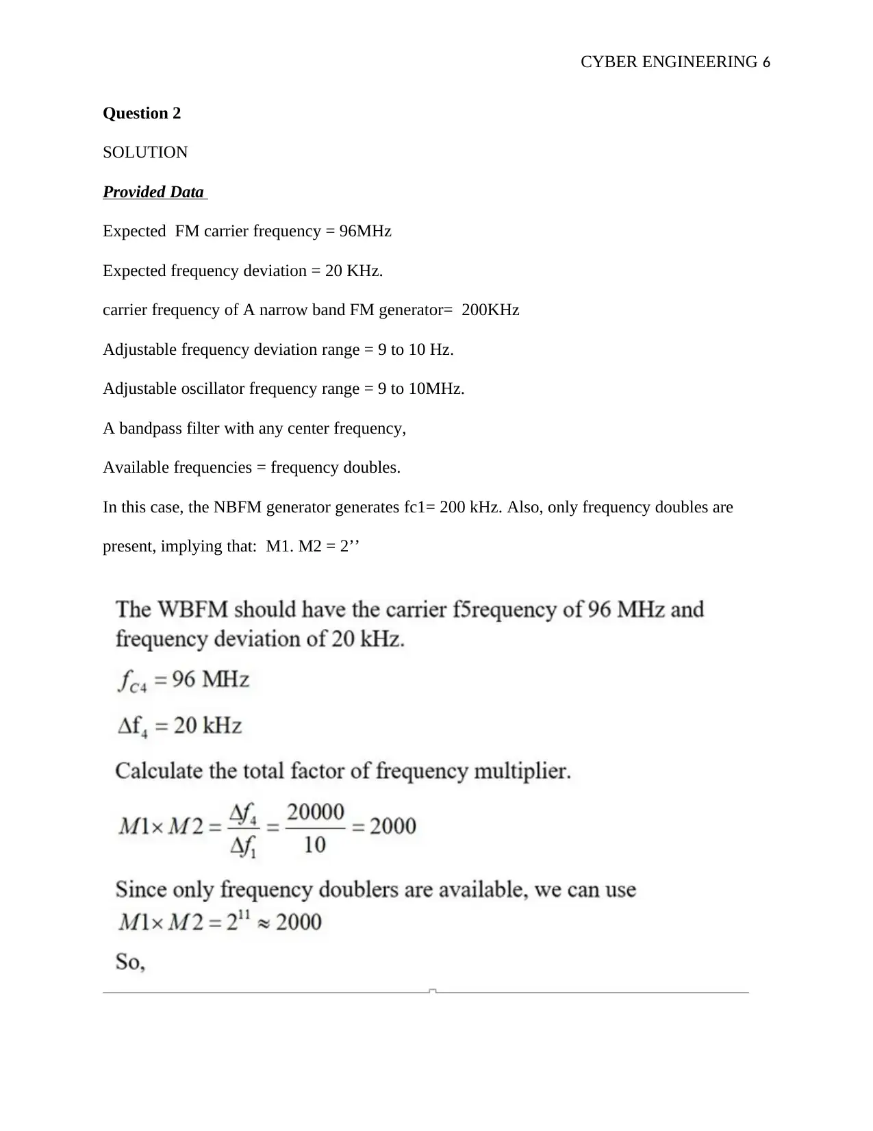
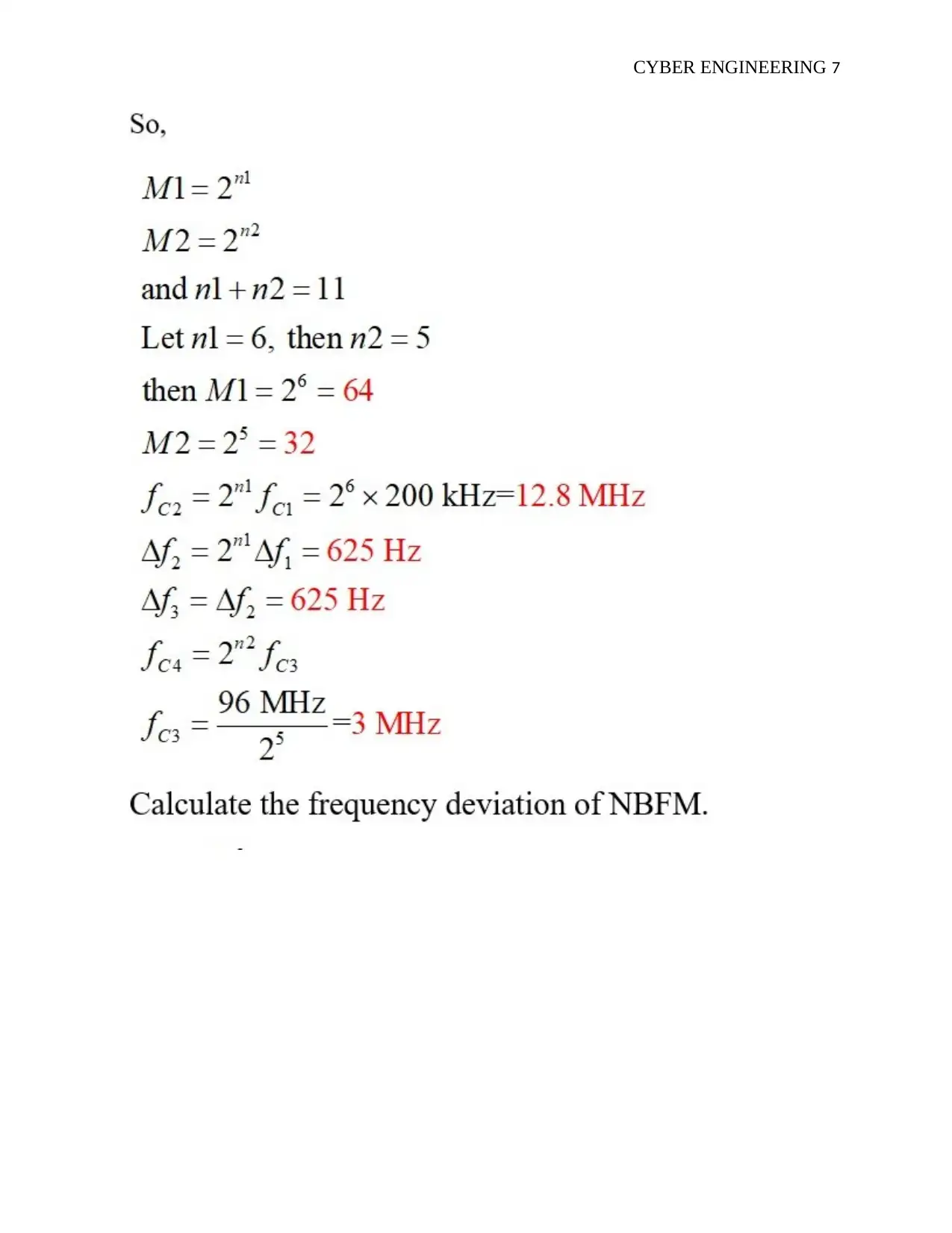
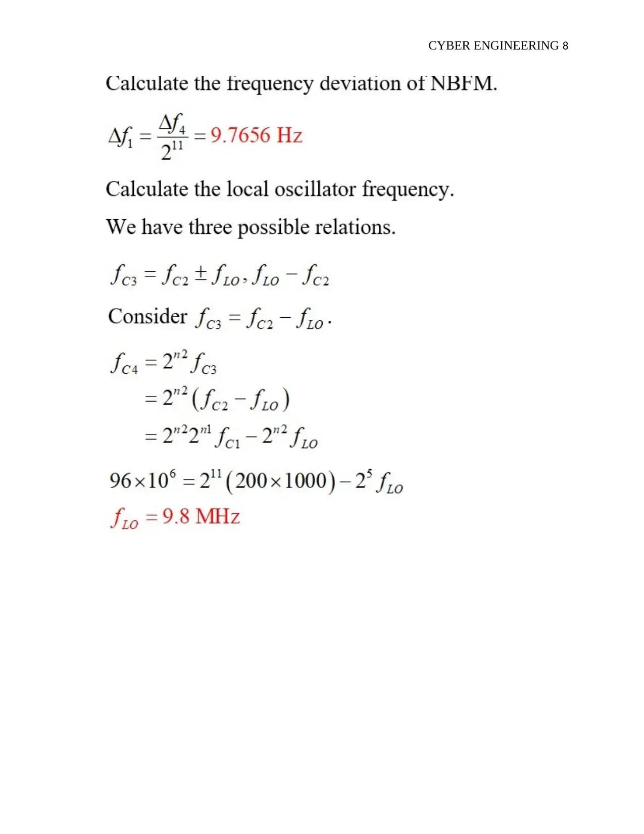
Expected FM carrier frequency = 96MHz
Expected frequency deviation = 20 KHz.
carrier frequency of A narrow band FM generator= 200KHz
Adjustable frequency deviation range = 9 to 10 Hz.
Adjustable oscillator frequency range = 9 to 10MHz.
A bandpass filter with any center frequency,
Available frequencies = frequency doubles.
In this case, the NBFM generator generates fc1= 200 kHz. Also, only frequency doubles are
present, implying that: M1. M2 = 2’’
Question 2
SOLUTION
Provided Data
Expected FM carrier frequency = 96MHz
Expected frequency deviation = 20 KHz.
carrier frequency of A narrow band FM generator= 200KHz
Adjustable frequency deviation range = 9 to 10 Hz.
Adjustable oscillator frequency range = 9 to 10MHz.
A bandpass filter with any center frequency,
Available frequencies = frequency doubles.
In this case, the NBFM generator generates fc1= 200 kHz. Also, only frequency doubles are
present, implying that: M1. M2 = 2’’
⊘ This is a preview!⊘
Do you want full access?
Subscribe today to unlock all pages.
Trusted by 1+ million students worldwide
CYBER ENGINEERING 7
Paraphrase This Document
Need a fresh take? Get an instant paraphrase of this document with our AI Paraphraser
CYBER ENGINEERING 8
CYBER ENGINEERING 9
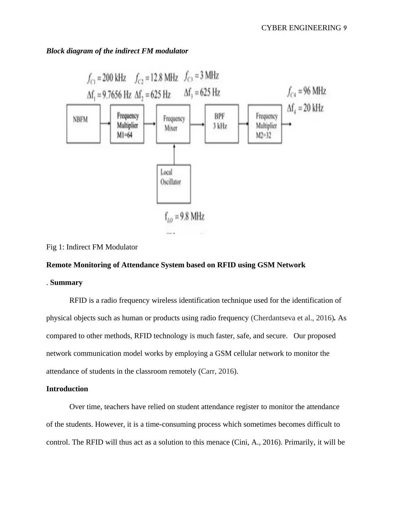
Block diagram of the indirect FM modulator
Fig 1: Indirect FM Modulator
Remote Monitoring of Attendance System based on RFID using GSM Network
. Summary
RFID is a radio frequency wireless identification technique used for the identification of
physical objects such as human or products using radio frequency (Cherdantseva et al., 2016). As
compared to other methods, RFID technology is much faster, safe, and secure. Our proposed
network communication model works by employing a GSM cellular network to monitor the
attendance of students in the classroom remotely (Carr, 2016).
Introduction
Over time, teachers have relied on student attendance register to monitor the attendance
of the students. However, it is a time-consuming process which sometimes becomes difficult to
control. The RFID will thus act as a solution to this menace (Cini, A., 2016). Primarily, it will be
⊘ This is a preview!⊘
Do you want full access?
Subscribe today to unlock all pages.
Trusted by 1+ million students worldwide

CYBER ENGINEERING 10
significant in universities, colleges, and schools. Some associated benefits of using RFID
technique incorporated with the GSM to monitor the student's attendance is that it is safe, secure,
and take a short time. The students will only be required to place their RFID card on a reader,
which will detect their attendance (Enokido & Takizawa, 2011).
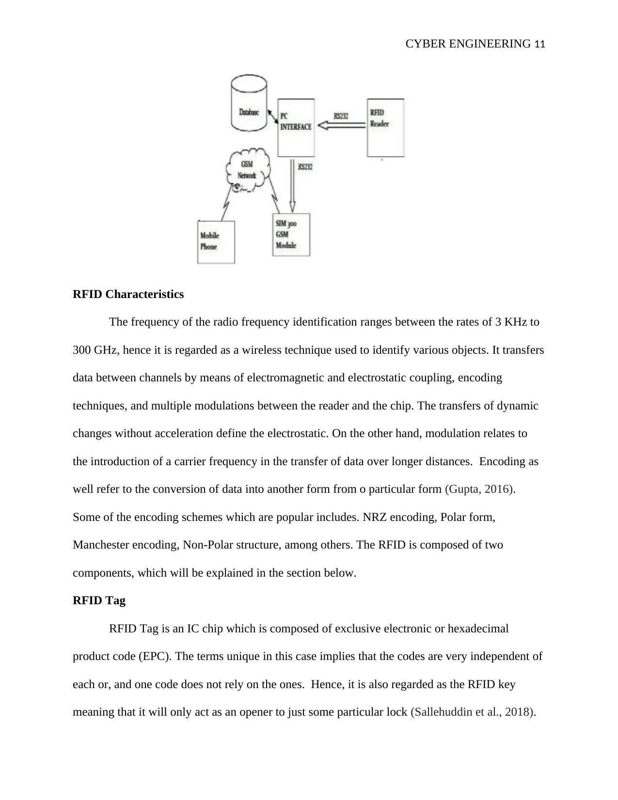
The attendance is deemed to be accurate since the system operates on a real-time basis.
The system will be linked to the computer by the help of an RS232 which will store the database
which has been collected (Pardini & Parreiras, F.S., 2016). A GSM short message service aid the
proposed system to carry out remote data monitoring. Vb language software is used to write the
communication as it assists in achieving real-time remote data synchronization and control of
serial interface port.
Design
Hardware structure
The hardware system will be composed of the following parts
Connecting wires
Sim card (Pardini, et al., 2017).
Power supply
Sim 300 gsm nodule with antenna
Rfid reader (Fielder et al., 2016
significant in universities, colleges, and schools. Some associated benefits of using RFID
technique incorporated with the GSM to monitor the student's attendance is that it is safe, secure,
and take a short time. The students will only be required to place their RFID card on a reader,
which will detect their attendance (Enokido & Takizawa, 2011).
The attendance is deemed to be accurate since the system operates on a real-time basis.
The system will be linked to the computer by the help of an RS232 which will store the database
which has been collected (Pardini & Parreiras, F.S., 2016). A GSM short message service aid the
proposed system to carry out remote data monitoring. Vb language software is used to write the
communication as it assists in achieving real-time remote data synchronization and control of
serial interface port.
Design
Hardware structure
The hardware system will be composed of the following parts
Connecting wires
Sim card (Pardini, et al., 2017).
Power supply
Sim 300 gsm nodule with antenna
Rfid reader (Fielder et al., 2016
Paraphrase This Document
Need a fresh take? Get an instant paraphrase of this document with our AI Paraphraser
CYBER ENGINEERING 11
RFID Characteristics
The frequency of the radio frequency identification ranges between the rates of 3 KHz to
300 GHz, hence it is regarded as a wireless technique used to identify various objects. It transfers
data between channels by means of electromagnetic and electrostatic coupling, encoding
techniques, and multiple modulations between the reader and the chip. The transfers of dynamic
changes without acceleration define the electrostatic. On the other hand, modulation relates to
the introduction of a carrier frequency in the transfer of data over longer distances. Encoding as
well refer to the conversion of data into another form from o particular form (Gupta, 2016).
Some of the encoding schemes which are popular includes. NRZ encoding, Polar form,
Manchester encoding, Non-Polar structure, among others. The RFID is composed of two
components, which will be explained in the section below.
RFID Tag
RFID Tag is an IC chip which is composed of exclusive electronic or hexadecimal
product code (EPC). The terms unique in this case implies that the codes are very independent of
each or, and one code does not rely on the ones. Hence, it is also regarded as the RFID key
meaning that it will only act as an opener to just some particular lock (Sallehuddin et al., 2018).
CYBER ENGINEERING 12
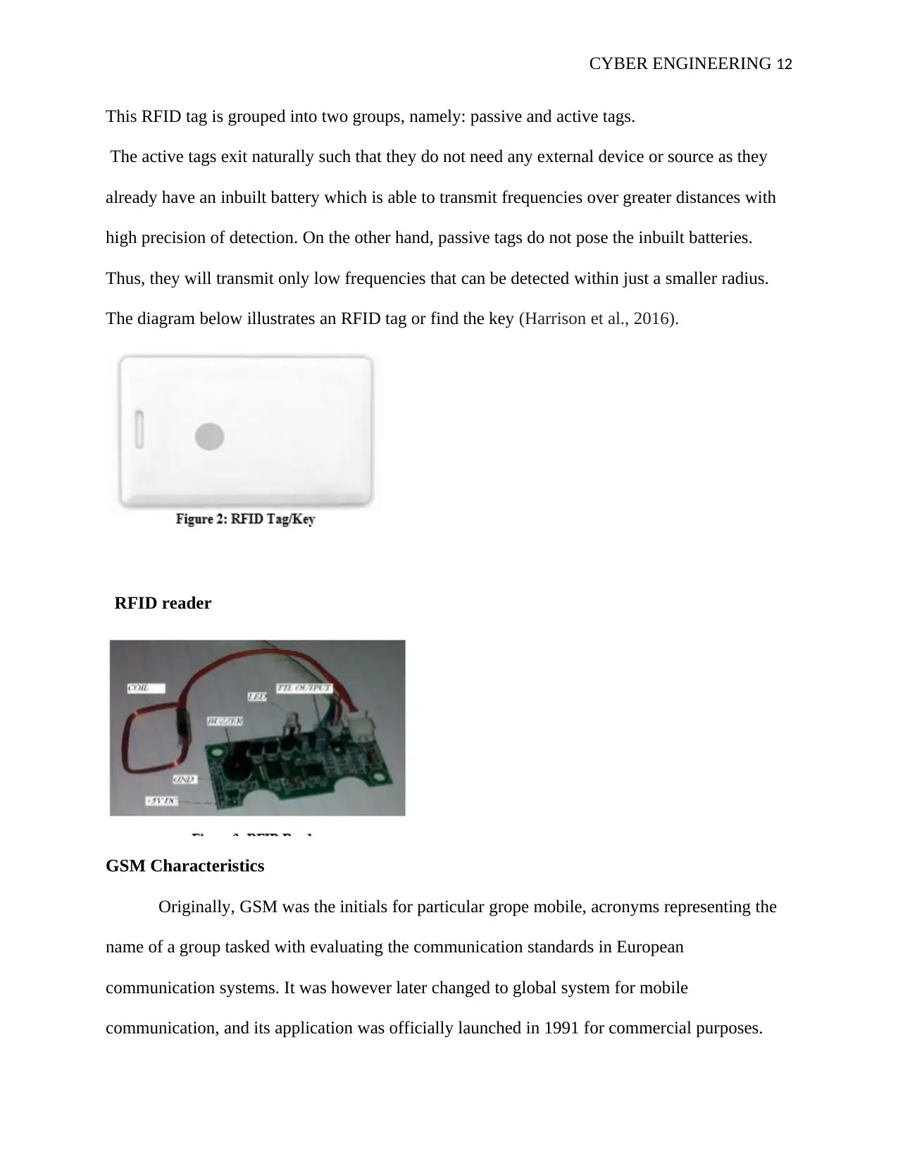
This RFID tag is grouped into two groups, namely: passive and active tags.
The active tags exit naturally such that they do not need any external device or source as they
already have an inbuilt battery which is able to transmit frequencies over greater distances with
high precision of detection. On the other hand, passive tags do not pose the inbuilt batteries.
Thus, they will transmit only low frequencies that can be detected within just a smaller radius.
The diagram below illustrates an RFID tag or find the key (Harrison et al., 2016).
RFID reader
GSM Characteristics
Originally, GSM was the initials for particular grope mobile, acronyms representing the
name of a group tasked with evaluating the communication standards in European
communication systems. It was however later changed to global system for mobile
communication, and its application was officially launched in 1991 for commercial purposes.
⊘ This is a preview!⊘
Do you want full access?
Subscribe today to unlock all pages.
Trusted by 1+ million students worldwide
1 out of 22

Your All-in-One AI-Powered Toolkit for Academic Success.
+13062052269
info@desklib.com
Available 24*7 on WhatsApp / Email
![[object Object]](/_next/static/media/star-bottom.7253800d.svg)
Unlock your academic potential
Copyright © 2020–2026 A2Z Services. All Rights Reserved. Developed and managed by ZUCOL.